A novel method to control stress distribution and machining-induced deformation for thin-walled metallic parts
-
Qian Bai
 ,
Dehua Song
,
Dehua Song

Abstract
In the precision machining of thin-walled planar components, the initial residual stress of the workpiece could lead to subsequent deformation after machining, which influences the geometrical accuracy of the final parts. Generally, conventional methods, such as stress-relief annealing and vibration stress relief, are implemented to reduce the magnitude of the residual stress. However, the distribution of the residual stress, which is more significant to the machining accuracy for thin-walled parts, is difficult to be adjusted in these methods. This article proposes a novel method to control the stress distribution and magnitude during the manufacturing process and thus reduce the machining-induced deformation for the thin-walled planar part of pure copper. In this method, symmetrical distribution of residual stress is introduced by multi-pass rolling, quenching, stress-relief annealing, and turnover turning. The stress field and deformation of the part are predicted by finite element modeling in the whole process. The part deformation after machining is verified by the experiments. The results show that compared with the traditional stress-relief annealing, this novel method could reduce the part deformation after machining and improve the geometrical accuracy for thin-walled parts.
1 Introduction
Weak stiffness thin-walled parts are important in reducing the weight and improving the performance of components, and are widely used in aviation, aerospace, and other fields [1,2]. A thin-walled part has a diameter-to-thickness ratio greater than 50. The manufacturing processes of these thin-walled parts mainly include casting, rolling, forging, welding, additive manufacturing, and machining, in which high magnitude and unevenly distributed residual stress could be generated. Residual stress is one of the main reasons for machining-induced deformation and poor geometric accuracy of weak stiffness thin-walled parts [3,4,5], which could lead to part failure and production cost increase. Therefore, it is very important to control the residual stress in terms of the magnitude and the distribution in the manufacturing processes of the thin-walled parts.
Many studies have been focused on the effect of residual stress magnitude on the machining-induced deformation. Residual stress magnitude, that is, the absolute value of residual stress, has a great influence on the part deformation after machining. Masoudi et al. [6] found that when the initial residual stress of an aluminum thin-walled part was increased from −80 to 40 MPa, the machining-induced deformation was increased from 25.87 to 65.12 µm. Wang et al. [7] developed a finite element (FE) model to predict the machining deformation of thin-walled parts. Based on the simulation results, the deformation after machining was increased from 170 to 530 µm when the initial residual stress was changed from 61 to 239 MPa. Huang et al. [8] stated that the initial residual stress and the machining-induced stress both had contribution on the part deformation after machining, and they found that for the three-frame monolithic beam part, the deformation caused by the initial residual stress accounted for 90% of the total deformation.
The residual stress distribution is also the key factor for the machining-induced deformation. Gao et al. [9] conducted FE simulations for the thin-walled plate in which the same residual stress magnitude was applied ranging from −230 to 180 MPa in different distributions. The result showed that the part deformation with a symmetrical distribution was reduced by 66.7% compared to that with an asymmetrical distribution. Cerutti et al. [10] stated that by changing the residual stress distribution of an aluminum part to a symmetrical manner, the part deformation after machining was decreased by 84.5%. Wu [11] found that with the asymmetrical and symmetrical stress distribution for thin-walled plate parts, the machining-induced deformation was 1 and 0.02 mm, respectively, which indicated that symmetrical stress distribution in the thickness direction was beneficial to the improvement of the geometrical accuracy for the thin-walled plate parts.
There are many stress-relief methods, which can effectively reduce the residual stress magnitude of the workpiece, such as mechanical stretching method [12], vibration stress relief [13,14], cryogenic treatment [15], and stress relief annealing [16,17]. In these methods, different types of external loads or energies are used to promote elastic strain inside the part into a stable plastic strain, so that the residual stress in the part is reduced [18]. Yoshihara and Hino [19] investigated the effect of different mechanical tensile plastic deformations on the elimination of residual stress in 7075-T6 aluminum bars and found that the residual stresses in the workpiece were decreased with the increase in tensile deformation. Robinson et al. [20] used the mechanical stretching method to eliminate residual stresses inside 7749 aluminum alloy material and found that the residual stress was reduced by 90% when the tensile plastic deformation was 2%. Walker et al. [21] reduced the residual stress of rolled low-alloy steel by 40% with the aid of vibration stress relief. Li et al. [22] used vibration stress relief to reduce the residual stress of DH36 steel welded members by 29–72%. Tanner and Robinson [23] performed a 12-h thermal aging treatment on aluminum alloy 2014 forgings and reduced the internal residual stress of the parts by 29.5%. These studies are mainly focused on different methods and the processing parameter determination to reduce the magnitude of the residual stress. However, the distribution of the residual stress, which is more significant to the machining accuracy, is difficult to be adjusted by these methods.
Traditional forming processes of pure copper plates include multi-pass rolling, annealing, and turnover turning. However, after the traditional forming process of pure copper plates, the residual stress distribution had a great effect on the machining-induced part deformation and thus the geometrical accuracy.
This article proposes a novel method to control the symmetrical distribution of the residual stress during the manufacturing process and thus reduce the machining-induced deformation for thin-walled planar parts of pure copper. In this method, as shown in Figure 1, multi-pass rolling is utilized to ensure the symmetrical stress distribution of the rolled part. Then, the symmetrical quenching stress distribution is introduced by the quenching for the rolled part. The stress-relief annealing is conducted to reduce the stress magnitude. Finally, the turnover turning realizes the symmetrical material removal and achieves the symmetrical distributed machining-induced residual stress. The stress field and deformation of the part are predicted by FE modeling in the whole process. The part deformation after machining is verified by the experiments. This new method to reduce the machining-induced part deformation by introducing symmetrical residual stresses could be applied to plane plate workpieces with other materials.

Schematic of symmetrical stress control process.
2 Experimental procedure of the symmetrical stress control process
In the proposed stress control experiment, the initial dimension of the pure copper plate was ϕ100 mm × 25 mm (Figure 2(a)). A double-roll synchronous mill (GZ200) with a roll diameter of 240 mm and a width of 320 mm was used (Figure 2(b)). Since the boundary conditions of the upper and the lower rollers were different, 15 passes were utilized in the multi-pass rolling process to ensure the symmetrical stress distribution of the rolled part, and the thickness reduction in each pass is shown in Table 1. The angular speed of the upper and the lower rollers was set to 0.2338 rad·s−1. After each pass, the rolled part was turned over and rotated 45° (Figure 2(c)). The operation was repeated until the rolled part with a dimension of ϕ220 mm × 5 mm was obtained, as shown in Figure 2(c) and (d).

Multi-pass rolling experiment: (a) initial plate of the pure copper, (b) double-roll synchronous mill, (c) rolled part, and (d) schematic of the 15-pass rolling process.
Rolling thickness reduction in each pass
| Pass | 1 | 2 | 3 | 4 | 5 | 6 | 7 | 8 | 9 | 10 | 11 | 12 | 13 | 14 | 15 |
| Thickness reduction (mm) | 2 | 2 | 2 | 2 | 2 | 2 | 2 | 1 | 1 | 1 | 1 | 0.5 | 0.5 | 0.5 | 0.5 |
After the rolling, the quenching experiment of the rolled part was conducted to introduce the symmetrical stress distribution. The rolled part was heated to 400°C in a vacuum heat treatment furnace (ZKKSL-1400X). Then, the part was dropped into a water tank along the radial direction of the plate, which generated a symmetrical stress distribution with a high magnitude in the thickness direction. Then, stress-relief annealing was conducted at a temperature of 400°C for 8 h to reduce the quenching-induced residual stress.
The rolled part was first machined by turning to a diameter of 200 mm. Then, the turnover turning experiment was conducted to realize the symmetrical material removal and achieve the symmetrical distributed machining-induced residual stress. A CKA6140 CNC lathe was used, and the tool material is carbide. Wax was utilized to adhere the thin-walled part to the clamping tool (Figure 3(a)). A spot-stick method is used to ensure the symmetrical material removal. Turning parameters are listed in Table 2. The final dimension of the thin-walled part after turning was ϕ200 mm × 3.5 mm (Figure 3(b)).

(a) Experimental setup of turning and (b) CMM path in the final part with a diameter of 200 mm and a thickness of 3.5 mm.
Turning parameters
| Cutting speed (m·min−1) | Feed (mm·r−1) | Cutting depth (mm) | |
|---|---|---|---|
| Semi-finishing | 160 | 0.12 | 0.2 |
| Finishing | 160 | 0.06–0.08 | 0.05–0.1 |
After heat treatment, normally the absolute value of residual stress is lower than 30 MPa [24]. The X-ray diffraction (XRD) method is the most commonly used method with a measurement accuracy of ±20 MPa [25], which is not capable of accurately measuring the residual stress with a small absolute value. Therefore, the part deformation after the turning was used to evaluate the stress in the thin-walled parts.
The part deformation was measured by the coordinate measuring machine (CMM, PRISMO1202022). The CMM scanning path is shown in Figure 3(b). The diameter of the scanning path ranged from 10 to 190 mm and gradually increased by 10 mm in turn. In each circle, coordinates of 200 locations were collected.
3 Analysis of residual stress in the whole process
In order to study the evolution of the residual stress in the proposed symmetrical stress control process, an FE model of the rolling, quenching, annealing, and turning process for thin-walled parts was established by the software ABAQUS. The data of the geometry, the stress, the strain, and the temperature field of the part were transferred to the subsequent steps.
3.1 Multi-pass rolling
An FE model of the multi-pass rolling was established, as shown in Figure 4. The material properties of pure copper defined in the FE model are listed in Table 3. The rollers were considered as rigid bodies. C3D8R hexahedral element was defined for the workpiece and the rollers. Two explicit kinetic analysis steps were set. The workpiece was first pushed into the rollers at a speed of 200 mm·s−1, and then, it was rolled by the rollers with an angular speed of 0.2338 rad·s−1 according to the experiment.

(a) FE model of multi-pass rolling: (b) before rolling, (c) during rolling, and (d) after rolling.
Material properties
| Density (kg·m−3) | Linear expansion coefficient | Poisson’s ratio | Young’s modulus (GPa) |
|---|---|---|---|
| 8,900 | 1.77 × 10⁻⁵ | 0.34 | 119 |
A high-temperature elastoplastic constitutive model, describing the relationship between flow stress, temperature, and strain rate, was used for the evaluation of residual stress changes by using the subroutine UHARD in ABAQUS. The model was in an Arrhenius type [26], and the material constants were fitted based on the hot compression test results in ref. [27]:
where
Fitted material constants
| Q | R | A | N | α |
|---|---|---|---|---|
| 114,965 | 8.314 | 1.598 × 10⁹ | 27.952 | 0.00398 |
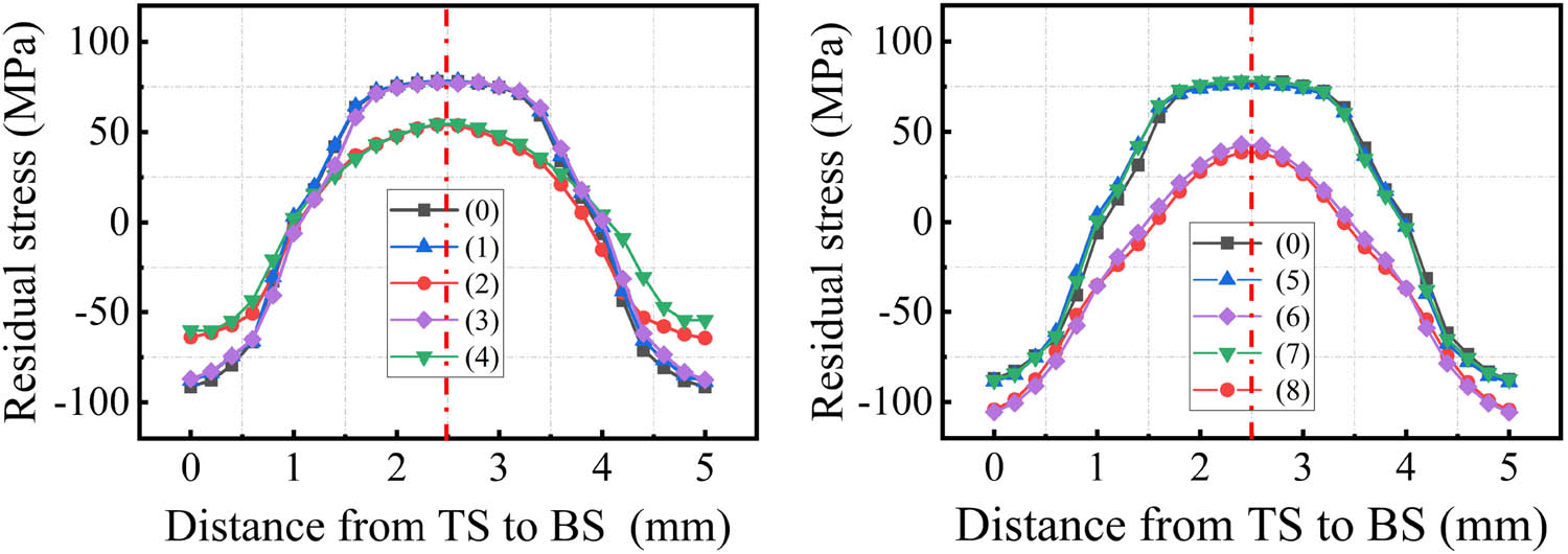
After 15-pass rolling, the residual stress distribution on the top surface of the part in the planar direction is shown in Figure 5(a). It is found that the residual stress was nonuniformly distributed due to the local plastic deformation of the material in the rolling. Tensile stress existed in the surface of the part with a magnitude of up to 240 MPa. Eight locations of the part were chosen in two radial directions as shown in Figure 5(a). The residual stress distributions in the thickness direction of these locations are shown in Figure 5(b). After the multi-rolling process, a symmetrical trend of residual stress distribution was achieved in the thickness direction of the part. However, in some locations, as shown in the dashed frames in Figure 5(b), asymmetrical residual stress distribution existed due to the uneven plastic deformation in the rolling process.

(a) Residual stress distribution in the planar direction on top surface and (b) residual stress distribution in the thickness direction for the typical locations in (a).
3.2 Quenching process
Quenching can introduce a symmetrical stress distribution in a plate. Wang et al. [28] and Chobaut et al. [29] proposed a model for calculating quenching residual stresses as follows:
where σ xx and σ yy are the stress in the X and Y directions of the plate, α is the coefficient of thermal expansion, E is the elastic modulus, and ν is Poisson’s ratio, ΔT = T 1 − T 2, where T 1 is the initial temperature and T 2 is the final temperature; h is the height from the center; P 1 = π 2 k/(ρch 2 ), where k is the thermal conductivity, ρ is the density of the material, c is the specific heat capacity, and t is the heat dissipation time. Based on equation (2), it is found that residual stresses caused by quenching were symmetric in thickness.
In order to control the residual stress to a symmetrical distribution, quenching was conducted to generate a large symmetrical residual stress in the rolled part. The residual stresses of the rolled part in Figure 5 were used as initial stress condition for the quenching process. The rolled part was then heated to 400°C (Figure 6(a)) and dropped from a height of 150 mm into the water of 20°C in the part radial direction by free-fall. During the quenching, the temperature of the part was decreased quickly (Figure 6(b) and (c)), which introduced a large symmetrical residual stress in the thickness direction. This thermal-induced residual stress was superimposed to the residual stress generated by the rolling, leading to a symmetrical stress distribution with a high magnitude after quenching. The quenching process was considered to be completed when the temperature difference in the part was less than 1°C (Figure 6(d)). Since the outside temperature of the workpiece drops quickly and the inside temperature drops slowly, the phenomenon of “symmetric temperature field” appears. However, the temperature difference of the workpiece is 0.3°C, and the overall temperature field of the workpiece is considered to be consistent.

Changes in temperature field during quenching cooling: (a) before cooling, (b) and (c) during cooling, and (d) after cooling.
The results of the residual stress distribution in the thickness direction of the quenched part are obtained in Figure 7. After the quenching process, the residual stress was symmetrical in the thickness direction.
Symmetrical stress distribution in the thickness direction after quenching.
Upon comparing Figure 7 with Figure 5, this stress distribution after quenching was totally different from that after rolling. The surface residual stress was compressive, and the internal residual stress was tensile due to the cooling histories at different locations. Due to the stress superposition, the magnitude of the residual stress was reduced to a value of around 100 MPa.
3.3 Stress-relief annealing process
The stress-relief annealing of 400°C was conducted to reduce the quenching-induced residual stress magnitude. A stress relaxation model was used to predict the stress evolution in the annealing process, which is expressed as follows [30]:
where
where A is the material constant,
In equation (4), n is the material constant, which is dependent on the extent of plastic deformation [31]:
where n
0 and B are the material constants, and
The slip resistance of dislocation
where
where
The dislocation density, considering initial hardening, annealing temperature, and annealing time, is described as follows [33,34]:
where
The volume fraction of recrystallization
where
Fitted parameters in the stress relaxation model
|
|
k s | a 3 | h 3 | n 3 | Q 3 |
|---|---|---|---|---|---|
| 0.01 | 1.9 | 5
|
1.65 | −3 | 108,000 |
|
|
Q | n 0 | B |
|
|
m |
|
l |
|
|---|---|---|---|---|---|---|---|---|---|
|
|
45,800 | 2.55 | 0.55 | 1.1
|
4
|
0.6 |
|
2 | 0.6 |
The fitted stress relaxation model was implemented into CREEP subroutine in ABAQUS. The stress field after quenching was transferred into the FE model of the annealing process as the initial stress. The heating temperature was defined as 400°C, and the heating time was 8 h. After stress-relief annealing, the residual stress magnitude was reduced to a level of 30 MPa, as shown in Figure 8, which is a 70% decrease compared to the quenching-induced stress. The symmetrical residual stress distribution generated by quenching was also maintained. Therefore, a small magnitude and highly symmetrical distribution of residual stress was obtained in the thickness direction by the proposed method for the thin-walled part.

Symmetrical stress distribution in the thickness direction after stress-relief annealing.
3.4 Turning-induced deformation prediction
After annealing, the absolute value of residual stress in the part was lower than 30 MPa. It is difficult to measure a low-stress value by XRD or hole drilling methods. The asymmetric distribution and high amplitude of residual stresses increase the amount of the part deformation. Therefore, the part deformation after the turning was used to evaluate the effect of residual stress control in the thin-walled parts [37].
In order to consider the residual stress induced by turning, the surface residual stress after turning was measured by electronic speckle pattern interferometry (ESPI) (Figure 9(a)). A micro-milling cutter (TSC-EM2R) with a diameter of 0.8 mm was selected for drilling, and the cutting speed was 100,000 rpm. The total measured depth was 100 µm with an interval of 10 µm. The residual stresses in the cutting and the feed direction are shown in Figure 9(b). The residual stress in the machined surface was tensile, and it was changed to be compressive with the increase in the depth. In the FE model for turning-induced deformation prediction, the turning-induced residual stress was superimposed to the residual stress field of the annealed part by the mapping method [35]. Subsequently, the material allowance was removed by using the birth–death element method to obtain a final part of ϕ200 mm × 3.5 mm. The deformation of the final part caused by the material removal and residual stress release was calculated and verified by experimental results.

(a) ESPI setup for the residual stress measurement and (b) measured results of residual stresses in the cutting and feed directions.
The machining-induced deformation results from the experiment and simulation were compared as shown in Figure 10. The predicted deformation had a good agreement with that from the experiment. The maximum error of the part deformation was 8 µm between the predicted and measured results, which could verify the accuracy of the FE model for stress control process.

Comparison between simulation and experimental results of part deformation.
The deformation of thin-walled parts by using the proposed method and the traditional stress-relief annealing method was compared as shown in Figure 11. The simulation results show that the machining-induced deformation by using the proposed method and the traditional annealing method was about 33 and 108 µm, respectively (Figure 11(a) and (b)). The experimental results by using these two methods were 27.5 and 89.0 µm, respectively, as shown in Figure 11(c) and (d). The prediction error of the part deformation was less than 21%. Since the diameter is 200 mm, the sub-millimeter level of part deformation was considered to be accurate and could be used to predict the residual stresses and the part deformation. Furthermore, by using the proposed method, the part deformation after machining was reduced by 67% compared with that using the traditional annealing. Therefore, it was verified that the proposed method could achieve the symmetrical distribution and low-magnitude residual stress in the thickness direction of parts, which is beneficial to the improvement of the machining geometrical accuracy for thin-walled parts.

Part deformation by using the proposed method based on (a) simulation, (c) experimental measurement, and by using the traditional stress-relief annealing method based on (b) simulation and (d) experimental measurement.
4 Conclusions
This article proposes a novel method to control the stress distribution and magnitude during the manufacturing process and thus reduce the machining-induced deformation for the thin-walled planar part of pure copper. The main conclusions are as follows:
Symmetrical distribution of residual stress was introduced by multi-pass rolling, quenching, stress-relief annealing, and turnover turning.
The FE model of the stress control process was developed to predict the residual stress evolution and the deformation after machining. The prediction error of the part deformation was less than 21%.
The simulation and experimental results show that compared with the traditional stress-relief annealing, the proposed method could reduce the part deformation by 67% after machining. A small deformation of 27.5 µm was achieved for the thin-walled part with a diameter of 200 mm and a thickness of 3.5 mm.
The proposed method achieved the symmetrical distribution and low-magnitude residual stress in the thickness direction of parts, which could be applied to the thin-walled parts with other materials such as aluminum and titanium alloys.
Acknowledgement
The financial support from the Science Challenge Project (JCKY2016212A506-0101) and the National Natural Science Foundation of China (52175381) is gratefully acknowledged.
-
Funding information: This research was financially supported by the Science Challenge Project (JCKY2016212A506-0101) and the National Natural Science Foundation of China (52175381).
-
Author contributions: Qian Bai: conceptualization, methodology, and draft preparation. Dehua Song: methodology and draft preparation. Wenmei Yang: conceptualization and methodology. Ziliang Chen: methodology. Jingang Tang: investigation. All authors have read and agreed to the published version of the manuscript.
-
Conflict of interest: Authors state no conflict of interest.
-
Data availability statement: Not applicable.
References
[1] Ning, H., W. Zhigang, J. Chengyu, and Z. Bing. Finite element method analysis and control stratagem for machining deformation of thin-walled components. Journal of Materials Processing Technology, Vol. 139, No. 1–3, 2003, pp. 332–336.10.1016/S0924-0136(03)00550-8Search in Google Scholar
[2] Wang, Z., J. Sun, L. Liu, R. Wang, and W. Chen. An analytical model to predict the machining deformation of frame parts caused by residual stress. Journal of Materials Processing Technology, Vol. 274, 2019, id. 116282.10.1016/j.jmatprotec.2019.116282Search in Google Scholar
[3] Cerutti, X. and K. Mocellin. Influence of the machining sequence on the residual stress redistribution and machining quality: Analysis and improvement using numerical simulations. The International Journal of Advanced Manufacturing Technology, Vol. 83, No. 1, 2016, pp. 489–503.10.1007/s00170-015-7521-4Search in Google Scholar
[4] Wang, Z., W. Chen, Y. Zhang, Z. T. Chen, and Q. Liu. Study on the machining distortion of thin-walled part caused by redistribution of residual stress. Chinese Journal of Aeronautics, Vol. 18, No. 2, 2005, pp. 175–179.10.1016/S1000-9361(11)60325-7Search in Google Scholar
[5] Guo, H., D. W. Zuo, H. B. Wu, F. Xu, and G. Q. Tong. Prediction on milling distortion for aero-multi-frame parts. Materials Science and Engineering: A, Vol. 499, No. 1–2, 2009, pp. 230–233.10.1016/j.msea.2007.11.137Search in Google Scholar
[6] Masoudi, S., S. Amini, E. Saeidi, and H. Eslami-Chalander. Effect of machining-induced residual stress on the distortion of thin-walled parts. The International Journal of Advanced Manufacturing Technology, Vol. 76, No. 1, 2015, pp. 597–608.10.1007/s00170-014-6281-xSearch in Google Scholar
[7] Wang, J., D. Zhang, B. Wu, and M. Luo. Prediction of distortion induced by machining residual stresses in thin-walled components. The International Journal of Advanced Manufacturing Technology, Vol. 95, No. 9, 2018, pp. 4153–4162.10.1007/s00170-017-1358-ySearch in Google Scholar
[8] Huang, X., J. Sun, and J. Li. Finite element simulation and experimental investigation on the residual stress-related monolithic component deformation. The International Journal of Advanced Manufacturing Technology, Vol. 77, No. 5, 2015, pp. 1035–1041.10.1007/s00170-014-6533-9Search in Google Scholar
[9] Gao, H., Y. Zhang, Q. Wu, and C. Liu. Influence of initial residual stress distribution on machining deformation of plate blank[C]//Advances in Energy Science & Environment Engineering: International Workshop on Advances in Energy Science & Environment Engineering. Advances in Energy Science and Environment Engineering, Vol. 1829, 2017, id. 020032.Search in Google Scholar
[10] Cerutti, X., K. Mocellin, S. Hassini, B. Blaysat, and E. Duc. Methodology for aluminium part machining quality improvement considering mechanical properties and process conditions. CIRP Journal of Manufacturing Science and Technology, Vol. 18, 2017, pp. 18–38.10.1016/j.cirpj.2016.07.004Search in Google Scholar
[11] Wu, Y. Quenching residual stress evolution and machining distortion of 2024 aluminum alloy blank. Master’s thesis. Harbin Institute of Technology, 2016.Search in Google Scholar
[12] Lobanov, L. M., V. I. Pavlovsky, and V. V. Lysak. Elastic pre-tension in aluminum alloy sheet welding. Schweisstechnic, 1987, pp. 447–449.Search in Google Scholar
[13] Sun, M. C., Y. H. Sun, and R. K. Wang. Vibratory stress relieving of welded sheet steels of low alloy high strength steel. Materials Letters, Vol. 58, No. 7–8, 2004, pp. 1396–1399.10.1016/j.matlet.2003.10.002Search in Google Scholar
[14] Yang, Y. P. Understanding of Vibration Stress Relief with Computation Modeling. Journal of Materials Engineering and Performance, Vol. 18, 2009, pp. 856–862.10.1007/s11665-008-9310-9Search in Google Scholar
[15] Bensely, A., S. Venkatesh, D. Mohan Lal, G. Nagarajan, A. Rajadurai, and K. Junik. Effect of cryogenic treatment on distribution of residual stress in case carburized En 353 steel. Materials Science and Engineering: A, Vol. 479, No. 1–2, 2008, pp. 229–235.10.1016/j.msea.2007.07.035Search in Google Scholar
[16] Epp, J., H. Surm, T. Hirsch, and F. Hoffmann. Residual stress relaxation during heating of bearing rings produced in two different manufacturing chains. Journal of Materials Processing Technology, Vol. 211, No. 4, 2011, pp. 637–643.10.1016/j.jmatprotec.2010.11.022Search in Google Scholar
[17] Wang, Z., A. D. Stoica, D. Ma, and A. M. Beese. Stress relaxation in a nickel-base superalloy at elevated temperatures with in situ neutron diffraction characterization: Application to additive manufacturing. Materials Science and Engineering: A, Vol. 714, 2018, pp. 75–83.10.1016/j.msea.2017.12.058Search in Google Scholar
[18] Wang, C., C. Jiang, and V. Ji. Thermal stability of residual stresses and work hardening of shot peened tungsten cemented carbide. Journal of Materials Processing Technology, Vol. 240, 2017, pp. 98–103.10.1016/j.jmatprotec.2016.09.013Search in Google Scholar
[19] Yoshihara, N. and Y. Hino. Removal technique of residual stress in 7075 aluminum alloy. Residual Stresses III: Science and Technology, 1991, pp. 23–26.Search in Google Scholar
[20] Robinson, J. S., S. Hossain, C. E. Truman, A. M. Paradowska, D. J. Hughes, R. C. Wimpory, et al. Residual stress in 7449 aluminium alloy forgings. Materials Science and Engineering: A, Vol. 527, No. 10–11, 2010, pp. 2603–2612.10.1016/j.msea.2009.12.022Search in Google Scholar
[21] Walker, C. A., A. J. Waddell, and D. J. Johnston. Vibratory stress relief—an investigation of the underlying processes. Proceedings of the Institution of Mechanical Engineers. Part E: Journal of Process Mechanical Engineering, Vol. 209, No. 1, 1995, pp. 51–58.10.1243/PIME_PROC_1995_209_228_02Search in Google Scholar
[22] Li, S. Q., H. Y. Fang, and X. Liu. Influence of vibration stress relief (VSR) on the residual stress and microstructure in welded plate of DH36 low alloy high strength steel[C]//Advanced Materials Research, Trans Tech Publications Ltd, Switzerland, Vol. 887, 2014, pp. 924–928.10.4028/www.scientific.net/AMR.887-888.924Search in Google Scholar
[23] Tanner, D. A. and J. S. Robinson. Reducing residual stress in 2014 aluminum alloy die forgings. Materials & Design, Vol. 29, No. 7, 2008, pp. 1489–1496.10.1016/j.matdes.2007.07.002Search in Google Scholar
[24] Bai, Q., H. Feng, L. K. Si, R. Pan, and Y. Q. Wang. A novel stress relaxation modeling for predicting the change of residual stress during annealing heat treatment. Metallurgical and Materials Transactions A, Vol. 50, No. 12, 2019, pp. 5750–5759.10.1007/s11661-019-05454-zSearch in Google Scholar
[25] Withers, P. J. and H. K.D. H. Bhadeshia. Residual stress. I – Measurement techniques. Materials Science and Technology, Vol. 17, No. 4, 2001, pp. 355–365.10.1179/026708301101509980Search in Google Scholar
[26] Peleg, M., M. D. Normand, and M. G. Corradini. The Arrhenius equation revisited. Critical Reviews in Food Science and Nutrition, Vol. 52, No. 9, 2012, pp. 830–851.10.1080/10408398.2012.667460Search in Google Scholar PubMed
[27] Liu, Y., W. Xiong, Q. Yang, J. W. Zeng, W. Zhu, and G. Sunkulp. Constitutive behavior and processing map of T2 pure copper deformed from 293 to 1073 K. Journal of Materials Engineering and Performance, Vol. 27, No. 4, 2018, pp. 1812–1824.10.1007/s11665-018-3210-4Search in Google Scholar
[28] Wang, X., Z. Xiaoyu, and H. Peisheng. Computational model for residual stresses in the straightening process of quenched high-strength plates. Engineering Science and Technology, Vol. 53, No. 03, 2021, pp. 166–172.Search in Google Scholar
[29] Chobaut, N., J. Repper, T. Pirling, D. Carron, J. M. Drezet. Residual stress analysis in AA7449 as-quenched thick plates using neutrons and FE modelling[M]//ICAA13 Pittsburgh, Springer, Cham, 2012, pp. 285–291.10.1007/978-3-319-48761-8_44Search in Google Scholar
[30] Estrin, Y. Dislocation theory based constitutive modelling: Foundations and applications. Journal of Materials Processing Technology, Vol. 80, 1998, pp. 33–39.10.1016/S0924-0136(98)00208-8Search in Google Scholar
[31] Zheng, J. H., J. Lin, J. Lee, R. Pan, C. Li, and C. M. Davies. A novel constitutive model for multi-step stress relaxation ageing of a pre-strained 7xxx series alloy. International Journal of Plasticity, Vol. 106, 2018, pp. 31–47.10.1016/j.ijplas.2018.02.008Search in Google Scholar
[32] Frost, H. J. and M. F. Ashby. Deformation mechanism maps: The plasticity and creep of metals and ceramics, Pergamon Press, New York, 1982.Search in Google Scholar
[33] Sun, Z. C., H. Yang, G. J. Han, and X. G. Fan. A numerical model based on internal-state-variable method for the microstructure evolution during hot-working process of TA15 titanium alloy. Materials Science and Engineering: A, Vol. 527, No. 15, 2010, pp. 3464–3471.10.1016/j.msea.2010.02.009Search in Google Scholar
[34] Kocks, U. F. Laws for Work-Hardening and Low-Temperature Creep. Journal of Engineering Materials and Technology, Vol. 98, No. 1, 1976, pp. 76–85.10.1115/1.3443340Search in Google Scholar
[35] Avrami, M. Granulation, phase change, and microstructure kinetics of phase change. III. The Journal of chemical physics, Vol. 9, No. 2, 1941, pp. 177–184.10.1063/1.1750872Search in Google Scholar
[36] Siwecki, T. Modelling of microstructure evolution during recrystallization controlled rolling. ISIJ International, Vol. 32, No. 3, 1992, pp. 368–376.10.2355/isijinternational.32.368Search in Google Scholar
[37] Bai Q., Z. Chen, Y. Gao, H. Li, and J. Tang. Residual stress relaxation considering microstructure evolution in heat treatment of metallic thin-walled part. High Temperature Materials and Processes, Vol. 41, No. 1, 2022, pp. 364–374.10.1515/htmp-2022-0036Search in Google Scholar
© 2022 the author(s), published by De Gruyter
This work is licensed under the Creative Commons Attribution 4.0 International License.
Articles in the same Issue
- Research Articles
- Numerical and experimental research on solidification of T2 copper alloy during the twin-roll casting
- Discrete probability model-based method for recognition of multicomponent combustible gas explosion hazard sources
- Dephosphorization kinetics of high-P-containing reduced iron produced from oolitic hematite ore
- In-phase thermomechanical fatigue studies on P92 steel with different hold time
- Effect of the weld parameter strategy on mechanical properties of double-sided laser-welded 2195 Al–Li alloy joints with filler wire
- The precipitation behavior of second phase in high titanium microalloyed steels and its effect on microstructure and properties of steel
- Development of a huge hybrid 3D-printer based on fused deposition modeling (FDM) incorporated with computer numerical control (CNC) machining for industrial applications
- Effect of different welding procedures on microstructure and mechanical property of TA15 titanium alloy joint
- Single-source-precursor synthesis and characterization of SiAlC(O) ceramics from a hyperbranched polyaluminocarbosilane
- Carbothermal reduction of red mud for iron extraction and sodium removal
- Reduction swelling mechanism of hematite fluxed briquettes
- Effect of in situ observation of cooling rates on acicular ferrite nucleation
- Corrosion behavior of WC–Co coating by plasma transferred arc on EH40 steel in low-temperature
- Study on the thermodynamic stability and evolution of inclusions in Al–Ti deoxidized steel
- Application on oxidation behavior of metallic copper in fire investigation
- Microstructural study of concrete performance after exposure to elevated temperatures via considering C–S–H nanostructure changes
- Prediction model of interfacial heat transfer coefficient changing with time and ingot diameter
- Design, fabrication, and testing of CVI-SiC/SiC turbine blisk under different load spectrums at elevated temperature
- Promoting of metallurgical bonding by ultrasonic insert process in steel–aluminum bimetallic castings
- Pre-reduction of carbon-containing pellets of high chromium vanadium–titanium magnetite at different temperatures
- Optimization of alkali metals discharge performance of blast furnace slag and its extreme value model
- Smelting high purity 55SiCr automobile suspension spring steel with different refractories
- Investigation into the thermal stability of a novel hot-work die steel 5CrNiMoVNb
- Residual stress relaxation considering microstructure evolution in heat treatment of metallic thin-walled part
- Experiments of Ti6Al4V manufactured by low-speed wire cut electrical discharge machining and electrical parameters optimization
- Effect of chloride ion concentration on stress corrosion cracking and electrochemical corrosion of high manganese steel
- Prediction of oxygen-blowing volume in BOF steelmaking process based on BP neural network and incremental learning
- Effect of annealing temperature on the structure and properties of FeCoCrNiMo high-entropy alloy
- Study on physical properties of Al2O3-based slags used for the self-propagating high-temperature synthesis (SHS) – metallurgy method
- Low-temperature corrosion behavior of laser cladding metal-based alloy coatings on EH40 high-strength steel for icebreaker
- Study on thermodynamics and dynamics of top slag modification in O5 automobile sheets
- Structure optimization of continuous casting tundish with channel-type induction heating using mathematical modeling
- Microstructure and mechanical properties of NbC–Ni cermets prepared by microwave sintering
- Spider-based FOPID controller design for temperature control in aluminium extrusion process
- Prediction model of BOF end-point P and O contents based on PCA–GA–BP neural network
- Study on hydrogen-induced stress corrosion of 7N01-T4 aluminum alloy for railway vehicles
- Study on the effect of micro-shrinkage porosity on the ultra-low temperature toughness of ferritic ductile iron
- Characterization of surface decarburization and oxidation behavior of Cr–Mo cold heading steel
- Effect of post-weld heat treatment on the microstructure and mechanical properties of laser-welded joints of SLM-316 L/rolled-316 L
- An investigation on as-cast microstructure and homogenization of nickel base superalloy René 65
- Effect of multiple laser re-melting on microstructure and properties of Fe-based coating
- Experimental study on the preparation of ferrophosphorus alloy using dephosphorization furnace slag by carbothermic reduction
- Research on aging behavior and safe storage life prediction of modified double base propellant
- Evaluation of the calorific value of exothermic sleeve material by the adiabatic calorimeter
- Thermodynamic calculation of phase equilibria in the Al–Fe–Zn–O system
- Effect of rare earth Y on microstructure and texture of oriented silicon steel during hot rolling and cold rolling processes
- Effect of ambient temperature on the jet characteristics of a swirl oxygen lance with mixed injection of CO2 + O2
- Research on the optimisation of the temperature field distribution of a multi microwave source agent system based on group consistency
- The dynamic softening identification and constitutive equation establishment of Ti–6.5Al–2Sn–4Zr–4Mo–1W–0.2Si alloy with initial lamellar microstructure
- Experimental investigation on microstructural characterization and mechanical properties of plasma arc welded Inconel 617 plates
- Numerical simulation and experimental research on cracking mechanism of twin-roll strip casting
- A novel method to control stress distribution and machining-induced deformation for thin-walled metallic parts
- Review Article
- A study on deep reinforcement learning-based crane scheduling model for uncertainty tasks
- Topical Issue on Science and Technology of Solar Energy
- Synthesis of alkaline-earth Zintl phosphides MZn2P2 (M = Ca, Sr, Ba) from Sn solutions
- Dynamics at crystal/melt interface during solidification of multicrystalline silicon
- Boron removal from silicon melt by gas blowing technique
- Removal of SiC and Si3N4 inclusions in solar cell Si scraps through slag refining
- Electrochemical production of silicon
- Electrical properties of zinc nitride and zinc tin nitride semiconductor thin films toward photovoltaic applications
- Special Issue on The 4th International Conference on Graphene and Novel Nanomaterials (GNN 2022)
- Effect of microstructure on tribocorrosion of FH36 low-temperature steels