Development of a 4 stroke spark ignition opposed piston engine
-
Jorge P. Gregório


Abstract
The purpose of this project was to develop a low-cost OP engine, 4-stroke, gasoline by joining two single-cylinder reciprocating internal combustion engines with side valves on the block, removing the heads. The chosed engine was Model EY15 of Robin America. Joining these two engine blocks together made possible to build an opposed-piston engine (OPE) with two crankshafts. In this new engine, the combustion chamber is confined to the space inside the cylinder between the piston heads and the chamber between the valves. The pistons move in the cylinder axis in opposite directions, a feature typical of opposed-piston engines. After building the engine, parameters characteristic of the OPE, such as: rotational speed, torque, fuel consumption and emissions, were measured on an Eddy currents dynamometer. With the collected data, power, specific consumption and overall efficiency were calculated, allowing to conclude that the motor with the opposed-piston configuration is less expensive and is more powerful. The development of the opposed-piston engine in this project has shown that it is feasible to build one engine from a different one already in use, reducing the manufacturing and development costs. In addition, higher power can be obtained with better specific fuel consumption and less vibration.
1 Introduction
At the beginning of the development of this opposing piston engine design, it was found that there were grounds for further research in this area. Opposing piston engines were successfully used in almost all civil and military fields, where they set records of low consumption and high specific power, which still remain so many years later, despite the undeniable progress in this field [1]. However, two major obstacles were encountered: the first related to the restrictions imposed on the emissions of internal combustion engines (2 stroke opposing piston engines significantly exceed the legal limits in force, which led, for some time, to a minor interest in its development [2]), while the second is conditioned by the current economic crisis and the times of austerity imposed by the international situation (creating difficulties in investment on research of this type of engines). After an analysis of the potential of this type of engines, the two major obstacles were faced as challenges to overcome. A decision was taken to develop an internal combustion engine, 4-stroke, spark ignition, of opposing pistons. Since limited material resources were available, it was decided to develop a single cylinder engine with somewhat outdated technology, as the objectives were: to show the viability of the engine, to enable the discovery of possible ways to make this type of engines evolve and to try to find an answer to the question "why the internal combustion reciprocating piston engines of 4-stroke spark ignition have been supplanted in terms of performance by conventional engines?". The development should preferably focus on a lightweight and compact engine to be used in some aeronautical applications to replace boxer engines that dominate the market up to 8 kW of power (which would imply a two-stroke engine). However, emissions caused the choice to fall on an engine with a 4-stroke cycle over a 2-stroke one, although this would make it heavier and less compact than would be desirable for an aeronautical application. Nevertheless, during World War II, the majority of the piston engines were of 4-stroke [3], and in terms of specific power, were reached values still difficult today to match. This choice also allows for compatibility with widely reported gaseous effluent treatment systems.
2 The precursors
Opposite piston engines that were at the origin of this alternative four-stroke spark ignition alternative piston engine and that had the greatest impact on its development were: Gobron Brillié four-stroke spark-ignition engine (used successfully in automobiles in the early twentieth century) and two-stroke compression-ignition Junkers Jumo 205 engine (which was arguably the most successful opposing piston engine used in aeronautics until the end of World War II in civilian and military applications). This last engine inspired during the 30s, 40s and even 50s of the 20th century the development of this type of engines on both sides of the Atlantic from the former Soviet Union to the United States of America for almost all kinds of applications. During the research of the opposing piston engines, it was found that from the time the opposing piston two-stroke Diesel engines began to succeed, the four-stroke opposed spark ignition piston engines which at the beginning of the 20th century have been successfully applied in motor vehicles (notably in the French vehicle Gobron-Brillié), have ceased to be produced. Avehicle of this brand was the first car to beat the mythical mark of the 100 miles per hour [4]. The Gobron-Brillié engine was a two-cylinder four piston engine with a single crankshaft. Two of the pistons were connected in a classic manner to the crankshaft by connecting rod, while the other two were on top of the cylinders. The two last were joined by a bridge connected to the crankshaft by two very long lateral connecting rods, transmitting the movement of the two upper piston rods to the crankshaft. It appears that this engine was inspired by the opposing piston engine attributed to Wittig 1878 [2], one of the first opposing piston engines to succeed and in the Robson 1890 engine operating in a similar way. Incidentally, these two first opposing piston engines operated following a 4-stroke cycle with the intake and exhaust ports located in the combustion chamber. The Junkers Jumo 205 engine, developed in Germany in the 1930s, featured a light, compact double-crank configuration, operating with two-stroke compression ignition. This engine had a significant impact on civil and military aeronautical applications, such that it was manufactured under license by several manufacturers in civil applications. It was the only two-cycle diesel engine regularly used in aeronautics produced in large quantities [5]. Even today it continues to be considered the most efficient piston engine used in aviation [1]. It should be noted, that from 1910 onwards, the engines with the configuration of 2 crankshafts became more widely used as they enabled substantially more compact in-line arrangements than the single crankshaft configurations. This type of configuration was then followed by the majority of manufacturers, as demonstrated by the Junkers Jumo engine family, the Fairbanks Morse 38D, the Rolls Royce K60, the Leyland L60, the Climax Coventry H30 and the Kharkiv Morozov 6TD, in a wide range of fields of application.
3 Engine genesis summary
After this initial research phase was considered the hypothesis of constructing an engine of opposing pistons with two crankshafts. However, was considered more appropriate to opt for a 4-stroke Otto cycle engine over a 2-stroke diesel engine that could operate from more than one fuel at the lowest possible cost. For this, has been considered the possibility to construct the opposing pistons engine from another one already existing, reducing this way the cost of manufacture [6]. The choice was a gasoline or kerosene, side valve engine, of the Robin America brand, model EY15, of a water pump, see Figure 1, even if it presented a somewhat outdated configuration.
![Figure 1 Exterior image and schematic representation of the engine [7].](/document/doi/10.1515/eng-2018-0039/asset/graphic/j_eng-2018-0039_fig_001.jpg)
Exterior image and schematic representation of the engine [7].
4 Characterization of the source engine
In its original configuration, the Robin America, Inc. model EY15 engine, works as a conventional Otto 4-stroke gasoline engine. Working position is upright, with 143 cc displacement and 3.5 HP of maximum power at 4000 rpm, powered by carburetor, with side valves in the block, splash lubrication and transistorized magneto ignition.
5 Development of the opposing piston engine
The reciprocating internal combustion engine developed over the course of this work, from the junction of two blocks of the Robin EY15 engine, runs accordingly to the 4-stroke cycle, with spark ignition. It has 286 cc displacement and develops 7.3 hp of maximum power at 4000 rpm. The double crankshaft configuration was adopted, similar to the Junkers Jumo 205 engine, but operating in a horizontal position. Synchronization of the distribution and transmission of power was ensured by a gear train consisting of four right-toothed cogwheels (1.5 mm module, two 65-tooth center gears and two 56-tooth drive shafts). The engine is powered by gasoline and features the two original carburetors of the Model EY15, placed on both sides of the engine. The splashing lubrication system and the transi-stored magneto ignition also remained from the original engine. The central area of the cylinder has a combustion chamber with a volume of 60 cc, consisting of the space between the upper dead points of both pistons and the side chamber in where are placed the inlet and exhaust valves and the spark plug (similar to what happened with the Gobron Brillié engine). The first step in the construction of the opposing piston engine consisted in removing the heads of the two Robin EY15 in order to allow the two blocks to be joined together in the area of the head gasket. This joint allows both pistons to be face to face and to move in opposite directions. In this configuration, the axis of one cylinder is aligned with the axis of the other cylinder, so that the two cylinder assembly functions as a single cylinder, with one block exhaust valve in front of the inlet valve of the other, in the space between the two engine blocks. This allowed the reduction of the combustion chamber space, since intake valve opening and exhaust valve closing are almost at the same time. For the engine to work in this configuration, some problems have to be solved. First, the placement of the spark plug (the one of greatest technical difficulty), secondly the space between the two blocks raised some questions (compression ratio value), thirdly how to join the two motors so as to keep the axis of the cylinders perfectly aligned with the combustion chamber, and fourth (possibly the most complex), how to arrange for them to be synchronized (so that the pistons moved in opposite directions while the distribution system allowed simultaneous opening of both the intake valves and subsequently the simultaneous movement of both exhaust valves). The synchronization system must also ensure that the crankshafts retain their original direction of rotation and support the power transmission to be provided from the two crankshafts. Finally, it was necessary to put the carburetors back upright, with the inlet duct horizontal and arrange to control the two carburetors at the same time with the same command, abdicating from the original speed controller. The spark plug originally fitted to the engine head was installed in one of the engine blocks in the space between the valve seat and the cylinder as shown in Figure 2.

Side and top view of spark plug assembly.
Since the space for placing the spark plug was very small, a spark plug with a smaller diameter was used, so that it could fit between the cylinder and the valves without causing any interference with other engine components. In order to guarantee the necessary space for the opening of the valves (without compromising the compression ratio and allowing the gas exchanges in the central zone of the cylinder), an aluminum spacer duly rectified at the parallel faces, with 5.3 mmthickness was placed between the two engine blocks. The gaskets of the original head were preserved, which had 1.5 mm thickness. These gaskets maintained the original position by placing the aluminum spacer between them. The combustion chamber was 8.3 mm high. In order to ensure the alignment of the cylinders along a common axis of the two engine blocks, three guides were placed in the original drilling of the M8 bolts that tightened the original head (see Figure 3). On the bases of the blocks, two supports were made with construction steel and MIG welded. With the blocks aligned, 6 stainless steel rods (AISI 304L) with 10 mm diameter, threaded with M10 thread were used to ensure the union of the two motor blocks, as shown in the photo of Figure 3.

Detail of aluminum spacer, engine head gasket and union guides.
A gear train consisting of 4 spur gear wheels with 1.5 mm module, was used to synchronize the two crankshafts. The sprockets used in both drive shafts have 56 teeth, while the two intermediate gears have 65 teeth. The four-sprocket gear train enables the piston of one crankshaft to move in the opposite direction to the piston of the other, ensuring that the distribution moves at the right time both the intake and exhaust valves and that both crankshafts maintain the direction of rotation of the original engine. For this gear train, right-toothed cogwheels have been selected, as in the case of the Junkers Jumo 205 engine, to ensure power transmission to the PTO shaft without causing axial stresses on the crankshafts, which are not sized for this. To mount of the intermediate shafts, a steel plate fixed to the block was used with eight M8 bolts, which also helps to keep the blocks together. This steel plate was then reinforced with an L-flap where a transparent PETG cover was screwed in to mitigate the gear noise of the sprockets and prevent the lubricant used in the gears from splashing all around. It should be noted that part of this cover was then cut to allow the power to be transmitted to the drive shaft in the upper right-hand corner, as shown in Figure 4. In order to place the carburetors upright, a stainless steel duct with an internal diameter of 20 mm (a slightly smaller diameter than that of the intake manifold), was constructed. The duct has a 90° knee and a horizontal tube of sufficient length to place the carburetor in an upright position without causing any inconvenience or being affected by the hot air stream from the engine cooling, or exhaust manifold. The carburetors were positioned on both sides of the engine. In order to control both carburetors at the same time and with the same command, was decided to use a system consisting of a steel cable, a rod, connected to the steel cable, a cable, a pulley and a shift knob of a bike.

Final positioning of the reciprocating piston engine PTO for this design.
6 Experimental installation
The experimental installation consists on an engine test bench of the brand STEM-ISI Impianti, model TD340, equipped with a Borghi and Saveri, FE 150 model eddy currents brake and an analog controller of the Borghi and Saveri, model A03, STEM-ISI (1992), an infrared gas analyzer from Tecnotest, model MULTIGAS 488, for gasoline engines, an exhaust system, an additional cooling fan and a fuel consumption metering system (consisting of a calibrated fuel tank, a fuel container, a digital electronic scale with a resolution of 0.01 g and a digital timer with a resolution of 0.01 s). Figure 5 shows the OP engine in the dynamometric test bench, the installation and all the equipment.
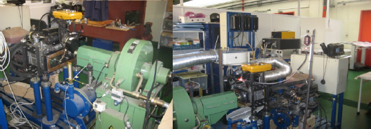
Overview of the dynamometric test bench and the opposing piston engine.
7 Characteristic parameters of internal combustion engines (ICE)
A review of the characteristic parameters of reciprocating internal combustion engines will be used to support the presentation and discussion of the experimental results. The torque, power and overall performance, are three of the most important characteristic parameters in any internal combustion engine. The effective brake power (in kW) is given by equation (1).
Where B is the torque and n is the rotational speed of the engine in revolutions per minute. The fuel consumption or mass flow rate of fuel is given by equation (2)
Where: ṁf is the mass of fuel and Δt is the time interval. The overall efficiency is given by the ratio between the effective brake power and the thermal power supplied to the motor, expressed in equation (3). In turn, the thermal power is given by the product of the mass flow rate of fuel by the lower heating value of that same fuel.
Where: Ẇb is the brake effective power, ṁf the fuel mass flow rate and HV is the lower heating value of the fuel. In the present case the fuel used is gasoline. For calculation purposes the value of 44000 kJ/kg for gasoline low heating value was considered [8].
In turn, the specific fuel consumption, Csf, is given by equation (4). This parameter relates the fuel consumption with the effective brake power and allows to obtain a good term of comparison between engines.
In the technical literature, the specific fuel consumption is usually presented in g/kWh. Accordingly, equation 4 was reformulated as presented in equation (5).
Where: ṁfh is the mass flow rate (g/h).
The consumption (per hour) of fuel, or mass flow rate of fuel in g/ h is given by equation (6).
The volumetric efficiency ηV, equation (7) [9], relates the amount of air actually introduced into the cylinder per cycle with the theoretical filling capacity of the cylinder in that same cycle. This is one of the most important parameters in the characterization and modeling of four-stroke internal combustion engines.
Where: ma is the mass that actually enters the cylinder in each cycle, mat, is the mass that would theoretically fill the cylinder, ρai, the density of the air (or mixture) under atmospheric conditions and Vd, the displaced volume. In theory, the mass of the fresh charge in each cycle should be equal to the product of the density of the air (or mixture) evaluated at atmospheric conditions outside the engine by the displacement, i.e., the volume displaced by the piston. However, due to the reduced time available for the admission and load losses due to the existing flow restrictions, only a smaller quantity of the theoretical amount of fresh charge entering the cylinder under atmospheric conditions [10] eventually enters the cylinder. The value of the volumetric efficiency depends on several engine variables, such as engine speed, inlet and exhaust manifold pressures, and system geometry [11]. In this case, equation (8) is presented as the ratio between the flow rate actually admitted in the cylinder and the mass flow rate that would theoretically be admitted for that speed of rotation.
Where: ηR represents the number of revolutions per cycle and ṁa the mass flow rate that actually enters the cylinder. In practical terms, the value of the volumetric efficiency is obtained from the type of cycle, torque, fuel air ratio, air density, displaced volume, overall efficiency and lower heating value of the fuel as shown in equation (9), which results from the combination of equations (1) and (4), among others.
Where: AF represents the fuel air ratio, considering the value of 14.7. The fuel air ratio (AF), equation (10), relates the mass of air to the mass of fuel mf . These relationships can also be presented as the relation between mass flow rates.
8 Results presentation
The data relating to the engine speed (rpm), torque (N.m), mass of fuel consumed, (g) and fuel consumption time (s) collected during the dynamometric tests at full engine load combined with the preceding equations allow to present the results (Figure 6). This graph results from the overlapping of two graphs, the first one where power is presented and the second one where power and specific consumption are presented. In both graphs the horizontal axis is the speed of rotation of the engine (rpm). The vertical axis on the left side, is for the brake power (kW), the right-hand axis, is for the brake torque values (N.m). In the lower part of the right axis the values of the brake specific consumption (g/kWh) can be read. The orange dots represent the results of effective brake power, blue dots the torque data and specific consumption appears as red at the bottom. The corresponding lines result from the second-order polynomial interpolation done in Excel software. The curves follow the expected trend, however it should be noted that the reduction of torque from 2400 rpm to 2800 does not continue to check at 3200 and 3600. In fact, only at 4000 rpm a decrease in torque is noticed again. The values obtained at 2800 rpm seem to constitute a singularity, even for the specific consumption that presents values higher than the values of the tests of nearer speed.

Characteristic curves of the engine.
In the graph of Figure 7 can be seen the results of the global efficiency and its second-order polynomial trend curve made in Excel. This graph shows an efficiency loss at 2800 rpm, with the best overall yield appearing in the next test at 3200 rpm.

Overall engine performance curve.
The graph of Figure 8 shows the results of the volumetric efficiency and its second-order polynomial trend curve made in Excel. It is possible to observe that the trend curve shows a slight decrease from 1600 rpm up to 2800 rpm value from which there appears to be an almost imperceptible decrease. If opting for a linear trend line the difference would be practically insignificant.

Volumetric efficiency curve as a function of rotational speed.
9 Conclusions
The development of the opposing piston engine resulting from the joining of two identical engines has shown that it is feasible to build one engine from an existing one, thereby reducing its manufacturing and development cost. In addition, higher power, better specific consumption and higher throughput are achieved with OPE. The results of the development of this engine of opposing pistons also enabled the identification of the areas where this engine exceeded and where there can be a wide range of possibilities of evolution on the investigation of this type of engines, namely in the improvement of the combustion conditions. Among the various possibilities is the modernization of the control and power system of the engine with the use of electronic ignition management, direct injection of fuel, supercharging and construction of a more compact combustion chamber that promotes the intensification of turbulent movement after ignition of the blend.
Acknowledgement
The current study was funded in part by Fundação para a Ciência e Tecnologia (FCT), under project UID/EMS/00151/2013 C-MAST, with reference POCI-01-0145-FEDER-007718.
References
[1] Brójo F., Santos A., Gregório, J. (2010, June 30 - July 2). Computational Analysis of the Scavenging of a two-stroke Opposed Piston Diesel Engine. Proceddings of the world Congresss on Engineering 2010 Vol II, WCE 2010, (London, United Kingdom): 1448-1453.Search in Google Scholar
[2] Pirault J-P., Flint M. (2009). Opposed Piston Engines: Evolution, Use, and Future Applications, Warrendale: SAE International.10.4271/R-378Search in Google Scholar
[3] Fernandes A. (2008). Compêndio de Motores Alternativos, Centro de Formação Militar e Técnica, Portugal: Força Aérea Portuguesa, Ministério da Defesa Nacional.Search in Google Scholar
[4] The Autocar. The Autocar Handbook, a Guide to the motor car (9th edition), London: Iliffe and Sons.Search in Google Scholar
[5] Gonçalves R. (2014). 3D CFD Simulation of a Cold Flow Four-Stroke Opposed Piston Engine (MSc. Dissertation). Covilhã: Universidade da Beira Interior.Search in Google Scholar
[6] Alves, F. (2011), Rendimento volumétrico de ummotor de pistões opostos a quatro tempos (MSc. Dissertation). Covilhã: University of Beira Interior.Search in Google Scholar
[7] Service Manual EY15-3, EY20-3 Engines (2001), Robin America, Inc.Search in Google Scholar
[8] Martins J., Motores de Combustão Interna (2005), Porto: Publindustria.Search in Google Scholar
[9] Heywood J., Internal Combustion Fundamentals (1988), New-York: McGraw-Hill International Editions.Search in Google Scholar
[10] Pesic R., Davinic A., Petkovic S., Taranovic D., Miloradovic D. (2013). Aspects of volumetric efficiency measurement for reciprocating engines. Thermal Science 17-1, 35-48.10.2298/TSCI120531153PSearch in Google Scholar
[11] Nicolau G., Scattolini R., Siviero C. (1996). Modelling the volumetric efficiency of ic engines: Parametric, non-parametric and neural techniques. Control Engineering Practice 4-10, 1405-1415.10.1016/0967-0661(96)00150-5Search in Google Scholar
© 2018 J. P. Gregório and F. M. Brójo, published by De Gruyter
This work is licensed under the Creative Commons Attribution-NonCommercial-NoDerivatives 4.0 License.
Articles in the same Issue
- Regular Article
- Real-scale comparison between simple and composite raw sewage sampling
- 10.1515/eng-2018-0017
- The risks associated with falling parts of glazed facades in case of fire
- Implementation of high speed machining in thin-walled aircraft integral elements
- Evaluating structural crashworthiness and progressive failure of double hull tanker under accidental grounding: bottom raking case
- Influence of Silica (SiO2) Loading on the Thermal and Swelling Properties of Hydrogenated-Nitrile-Butadiene-Rubber/Silica (HNBR/Silica) Composites
- Statistical Variations and New Correlation Models to Predict the Mechanical Behavior and Ultimate Shear Strength of Gypsum Rock
- Analytic approximate solutions to the chemically reactive solute transfer problem with partial slip in the flow of a viscous fluid over an exponentially stretching sheet with suction/blowing
- Thermo-mechanical behavior simulation coupled with the hydrostatic-pressure-dependent grain-scale fission gas swelling calculation for a monolithic UMo fuel plate under heterogeneous neutron irradiation
- Optimal Auxiliary Functions Method for viscous flow due to a stretching surface with partial slip
- Vibrations Analysis of Rectangular Plates with Clamped Corners
- Evaluating Lean Performance of Indian Small and Medium Sized Enterprises in Automotive Sector
- FPGA–implementation of PID-controller by differential evolution optimization
- Thermal properties and morphology of polypropylene based on exfoliated graphite nanoplatelets/nanomagnesium oxide
- A computer-based renewable resource management system for a construction company
- Hygrothermal Aging of Amine Epoxy: Reversible Static and Fatigue Properties
- The selected roof covering technologies in the aspect of their life cycle costs
- Influence of insulated glass units thickness and weight reduction on their functional properties
- Structural analysis of conditions determining the selection of construction technology for structures in the centres of urban agglomerations
- Selection of the optimal solution of acoustic screens in a graphical interpretation of biplot and radar charts method
- Subsidy Risk Related to Construction Projects: Seeking Causes
- Multidimensional sensitivity study of the fuzzy risk assessment module in the life cycle of building objects
- Planning repetitive construction projects considering technological constraints
- Identification of risk investment using the risk matrix on railway facilities
- Comparison of energy parameters of a centrifugal pump with a multi-piped impeller in cooperation either with an annular channel and a spiral channel
- Influence of the contractor’s payment method on the economic effectiveness of the construction project from the contractor’s point of view
- Special Issue Automation in Finland
- Diagnostics and Identification of Injection Duration of Common Rail Diesel Injectors
- An advanced teaching scheme for integrating problem-based learning in control education
- A survey of telerobotic surface finishing
- Wireless Light-Weight IEC 61850 Based Loss of Mains Protection for Smart Grid
- Smart Adaptive Big Data Analysis with Advanced Deep Learning
- Topical Issue Desktop Grids for High Performance Computing
- A Bitslice Implementation of Anderson’s Attack on A5/1
- Efficient Redundancy Techniques in Cloud and Desktop Grid Systems using MAP/G/c-type Queues
- Templet Web: the use of volunteer computing approach in PaaS-style cloud
- Using virtualization to protect the proprietary material science applications in volunteer computing
- Parallel Processing of Images in Mobile Devices using BOINC
- “XANSONS for COD”: a new small BOINC project in crystallography
- Special Issue on Sustainable Energy, Engineering, Materials and Environment
- An experimental study on premixed CNG/H2/CO2 mixture flames
- Tidal current energy potential of Nalón river estuary assessment using a high precision flow model
- Special Spring Issue 2017
- Context Analysis of Customer Requests using a Hybrid Adaptive Neuro Fuzzy Inference System and Hidden Markov Models in the Natural Language Call Routing Problem
- Special Issue on Non-ferrous metals and minerals
- Study of strength properties of semi-finished products from economically alloyed high-strength aluminium-scandium alloys for application in automobile transport and shipbuilding
- Use of Humic Sorbent from Sapropel for Extraction of Palladium Ions from Chloride Solutions
- Topical Issue on Mathematical Modelling in Applied Sciences, II
- Numerical simulation of two-phase filtration in the near well bore zone
- Calculation of 3D Coordinates of a Point on the Basis of a Stereoscopic System
- The model of encryption algorithm based on non-positional polynomial notations and constructed on an SP-network
- A computational algorithm and the method of determining the temperature field along the length of the rod of variable cross section
- ICEUBI2017 - International Congress on Engineering-A Vision for the Future
- Use of condensed water from air conditioning systems
- Development of a 4 stroke spark ignition opposed piston engine
- Development of a Coreless Permanent Magnet Synchronous Motor for a Battery Electric Shell Eco Marathon Prototype Vehicle
- Removal of Cr, Cu and Zn from liquid effluents using the fine component of granitic residual soils
- A fuzzy reasoning approach to assess innovation risk in ecosystems
- Special Issue SEALCONF 2018
- Brush seal with thermo-regulating bimetal elements
- The CFD simulation of the flow structure in the sewage pump
- The investigation of the cavitation processes in the radial labyrinth pump
- Testing of the gaskets at liquid nitrogen and ambient temperature
- Probabilistic Approach to Determination of Dynamic Characteristics of Automatic Balancing Device
- The design method of rubber-metallic expansion joint
- The Specific Features of High-Velocity Magnetic Fluid Sealing Complexes
- Effect of contact pressure and sliding speed on the friction of polyurethane elastomer (EPUR) during sliding on steel under water wetting conditions
- Special Issue on Advance Material
- Effect of thermo-mechanical parameters on the mechanical properties of Eurofer97 steel for nuclear applications
- Failure prediction of axi-symmetric cup in deep drawing and expansion processes
- Characterization of cement composites based on recycled cellulosic waste paper fibres
- Innovative Soft Magnetic Composite Materials: Evaluation of magnetic and mechanical properties
- Statistical modelling of recrystallization and grain growth phenomena in stainless steels: effect of initial grain size distribution
- Annealing effect on microstructure and mechanical properties of Cu-Al alloy subjected to Cryo-ECAP
- Influence of heat treatment on corrosion resistance of Mg-Al-Zn alloy processed by severe plastic deformation
- The mechanical properties of OFHC copper and CuCrZr alloys after asymmetric rolling at ambient and cryogenic temperatures