Implementation of high speed machining in thin-walled aircraft integral elements
-
Paweł Bałon
 ,
Edward Rejman
,
Edward Rejman

Abstract
High speed milling (HSM) is currently one of the most important technologies used in the aviation industry, especially concerning aluminium alloys. The difference between HSM and other milling techniques is the ability to select cutting parameters – depth of the cut layer, feed rate, and cutting speed, in order to simultaneously ensure high quality, precision of the machined surface, and high machining efficiency, all of which shorten the manufacturing process of the integral components. By implementing the HSM technology, it is possible to manufacture very complex integral thin-walled aerial parts from the full quantity of the raw material. At present, aircraft structures are designed to mainly consist of integral elements which have been produced by welding or riveting of component parts in technologies utilized earlier in the production process. Parts such as ribs, longitudinals, girders, frames, coverages of fuselage and wings can all be categorized as integral elements. These parts are assembled into larger assemblies after milling. The main aim of the utilized treatments, besides ensuring the functional criterion, is obtaining the best ratio of strength to construction weight. Using high milling speeds enables economical manufacturing of integral components by reducing machining time, but it also improves the quality of the machined surface. It is caused by the fact that cutting forces are significantly lower for high cutting speeds than for standard machining techniques.
1 Introduction
Aeroplane structures are exposed to many loads during their working lifespan. Every particular action made during a flight is composed of a series of air movements which generate various aeroplane loads. One rigorous requirement which modern aeroplane structures must meet is that they be of high durability and reliability. This requirement involves taking many restrictions into account during the aeroplane design process. The most important factor is the structure’s overall mass, which has a crucial impact on both utility properties and cost-effectiveness. This makes aeroplanes one of the most compound results of modern technology.
Almost every currently produced aeroplane structure, or to be more precise, aeroplane core structure, is manufactured as a thin-walled composition which perfectly meets the requirements concerning the structure’s mass minimisation. Some compositions have coverages reinforced with longitudinal and transverse elements which provide the required stiffness and strength of the whole composition. Local buckling of the coverage is allowed under load conditions, but exceeding the critical load levels of the elements such as frames or longitudinals virtually guarantees the structure’s destruction.
The methodology mentioned above forces constant improvements in both design methods and aeroplanes’ structural solutions. Development of material science and technological processes allows for the fabrication of geometrically compound integral structures. These structures enable the utilization of material characteristics in a more reasonable way, and also a significant increase in their core structure mechanical properties. The most important advantage of using the integral structures is the costs saving from the reduction or elimination of assembly operations.
Close-ribbed covering elements increase strength parameters and reduce the weight of the core structure. It is possible to achieve a structure with significantly higher critical loads by reducing covering thickness and simultaneously, by implementing adequately close-packed and stiffened longitudinal elements. As a result, more beneficial gradients and stress distribution will also be obtained, which directly increase the structure’s fatigue life [1].
The machining of thin-walled elements generates a lot of technological issues related to deformation and elastic and plastic displacements of the workpiece. Due to displacements of the milled workpiece, vibrations can occur, and thus, geometric errors may surface in the structure of the workpiece. Furthermore, plastic deformation can also cause shape problems and be a source of internal stresses in the surface layer, which are very difficult to remove and lead to deformation of the workpiece after machining. Consequently, this leads to an increase in the manufacturing costs of machining operations, especially of thin-walled elements, due to shortages and increased manufacturing time.
It is recommended that multiple methods for minimizing machining errors be utilized to improve the quality of thin-walled elements, such as:
optimization of the machining strategy,
increasing the cutting speed vs
optimization of cutting parameters, especially feed per tooth fz and the thickness of the cut layer ae due to the minimization of the cutting force component perpendicular to the surface of the milled wall [5].
In the aviation industry, the geometry of an aircraft is designed according to the laws of aerodynamics. Then, the particular aircraft assemblies, subassemblies and parts are designed on the basis of the developed geometry. The designer has a limited area to design a part within, and he/she needs to conform it within the constraints of that area using the best (the highest) strength-to-weight ratio. The strength-to-weight ratio is the basis for selecting material types to be used in the construction of the aircraft. The parts are designed and the appropriate material types (aluminium, titanium, steel, composite) are selected depending on the loads which occur in the aircraft. Full block material, a forging, or a casting is used for blanks. The most commonly used materials for aircraft constructions are composites, aluminium alloys, and titanium alloys. In recent years, high competition in the aviation industry has caused very rapid development of modern manufacturing processing. Currently, a lot of aircraft parts are manufactured ”ready-made” from the full quantity of the material. The integral aircraft parts typically require removal of up to 95% of the material over the course of the production process. In order to realise such large volume machining processes, it is ncessary that highly efficient methods be used so that production can be cost-effective. High Speed Milling technology makes this possible. Moreover, the manufactured parts are homogenoeus and have better physical properties. The lack of riveted joints results in a lighter part structure with a higher strength-to-weight ratio [4]. A comparison of the ”buy-to-fly” ratio (the total weight of the purchased materials to the part mass of the finished aircraft) of some aircraft elements is presented in Table 1.
A comparison of ”buy-to-fly” ratios for various manufacturing technologies
| Manufacturing technology type | „Buy-to–fly” ratio |
|---|---|
| Machining from the forged block | 30 : 1 |
| Machining from the sections | 12 : 1 |
| Die forgings | 8 : 1 |
| Laser machining | 3 : 1 |
| Form casting | 1.4 : 1 |
| Pressure die-casting | 1.2 : 1 |
| Additive Manufacturing | 1.2 : 1 |
The results show that the High Speed Milling technology is one of the most material-consuming methods, resulting in a high percentage of material turned into chips. However, the remaining advantages, especially the reduction of the part’s production time resulted in further development of this technology. For instance, the manufacturing time of an F-15 aircraft’s aerodynamic brake has been reduced from about 3 months to 12 hours. An analysis of HSM technology usage in the aviation industry requires consideration of technical and economic factors significantly influencing the application of this method. The most important of these are:
Market requirements – increasing market competition presents greater challenges. Shortening procurement deadlines and reducing costs makes the HSM an effective tool to meet the demands of tightening procurement deadlines and cost reduction programs.
Materials – implementing new materials (which are more difficult for machining) increases the need for developing new machining solutions.
Quality – the requirement of parts and product quality influencens safety and this is caused by competition. Implementing HSM offers many new solutions in this field, for example reducing manual machining.
Production process – implementing HSM techniques causes a shortening of the production cycle by decreasing the number of operations and simplifying logistics.
Design and development – HSM technology enables rapid implementation of new products by linking HSM technology and the design process.
Product complexity – increasing demands relating to the functions of products, especially in the aviation industry, forces their accuracy and shape complexity, which can be ensured with the highly efficient HSM technology.
Manufacturing capabilities – implementing CAD/CAM systems related to HSM technology increases the manufacturing capabilities of companies making them more competitive on the market.
The main effect of implementing HSM is a significant reduction in machining time. Additional effects from using HSM are:
Simplified mounting
Lower cutting forces
More clean tool edges (lack of build-up on edges), which results in fewer deformations during the machining process
Smoother surfaces – a finishing machining is not required
Less wear on tools.
The CAM systems not only generate a tool path but are also used for its verification and optimization in order to reduce the error amount, possibly even to zero. The nature of the aviation industry is small-volume production which requires flexibility even at the stage of technological production preparation where the integrated CAD and CAM systems are especially useful.
The planning strategy for machining of thin-walled compound structures used in the aviation industry requires taking into account both the principles recommended for CNC machine programming and also the specific features of thin-walled structures with a high ratio of wall height to wall thickness, especially when using HSM. For HSM technology, it is important to choose an appropriate machining strategy, especially for smooth aircraft thin-walled structures such as frames, ribs, etc. In those cases, the typical parameter is the wall’s ratio of height-to-wall thickness. Three cases can be distinguished:
low height-to-thickness ratio <15:1
moderate height-to-thickness ratio <30:1
high height-to-thickness ratio >30:1
This ratio reflects the elastic stiffness of the workpiece and, consequently, the deformations which occur during machining. In order to reduce wall bending, the appropriate number of tool passes needs to be used. Moreover, the time of tool-workpiece contact needs to be reduced by using high cutting speeds and a low ratio of cutting depth ap to cut layer width ae. The stability of the tool and the machined wall has a great impact in the process. Milling in reverse should be used in the case of less rigid support of the thin-walled object. For a height-to-weight ratio <15:1, only one side of the wall should be machined in nonoverlapping passes. Milling needs to be repeated for the opposite side and the allowance needs to be left for finishing machining [6].
2 Experimental procedure
The aim of the technological and geometric research studies was the aircraft frame, made of an aluminium alloy 7075 (EN 10204) with a chemical composition as follows: Al 89.72%, Cu 0.09%, Mn 0.11%, Mg 1.6%, Zn 0.03%, Si+Fe 2.5%. The mechanical properties of the 7075 T6 alloy measured in the temperature of 21° C for a velocity tensile of 0,001 s–1 are as follows: tensile strength Rm = 562 MPa, yield strength Rp0,2 = 518 MPa, Young’s modulus E = 71,7 GPa, Poisson’s ratio v = 0,33, elongation = 13 %, and hardness = 180 HV1 (Figure 1). Two 60 x 1190 x 1215 mm blocks with a total weight of 243kg were used as semi-finished products and were delivered in a solution state.
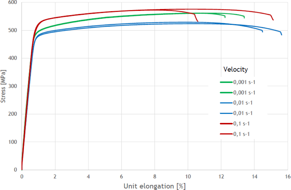
Stress-strain curve for aluminium alloy 7075
The overall dimensions of the workpiece were 1012 × 1354 × 55.8 mm. The walls were 1, 2 and 3 mm thick. The largest free flat surfaces (without ribs) were 393 × 385.4 × 1 mm. The ratio of the ribs height to its thickness h/g was in the range of 10-12.9. The passes radiuses between the walls and the ribs were 2 mm.
The frame was machined by the two DMU 75 machines (roughing). The machining was performed simultaneously at the two machines using different manufacturing technologies. The roughing was done with a spindle rotational speed of n=15 000 rpm and this was intended to prepare the machining datum surfaces for subsequent operations. The workpiece was mounted to the machine table by pressure clamps.
The machining was performed in two phases: shaping and finishing. Two workpieces were machined simultaneously on the two machines, while the symmetrical and asymmetrical machining of the pockets were used. In the first case, the frame pockets were oriented symetrically to the workpiece axis and they were machined in an alternate way. For asymmetrical machining, the pockets were milled alternately in relation to the symmetrical axis of the frame. For such treatment, integral deformations of the frame were estimated after the machining process.
Manufacturing of the double-sided frame pockets required preparing the machining bases and the bases needed to set and mount the workpiece on the milling machine. Therefore, a flange with cylindrical holes was made from the semi-finished material. The flange was a machining datum surface and the holes enabled mounting of the workpiece on the machine table (Figure 2). Those bases were removed in the final frame machining operation after being done ”on the ready”.
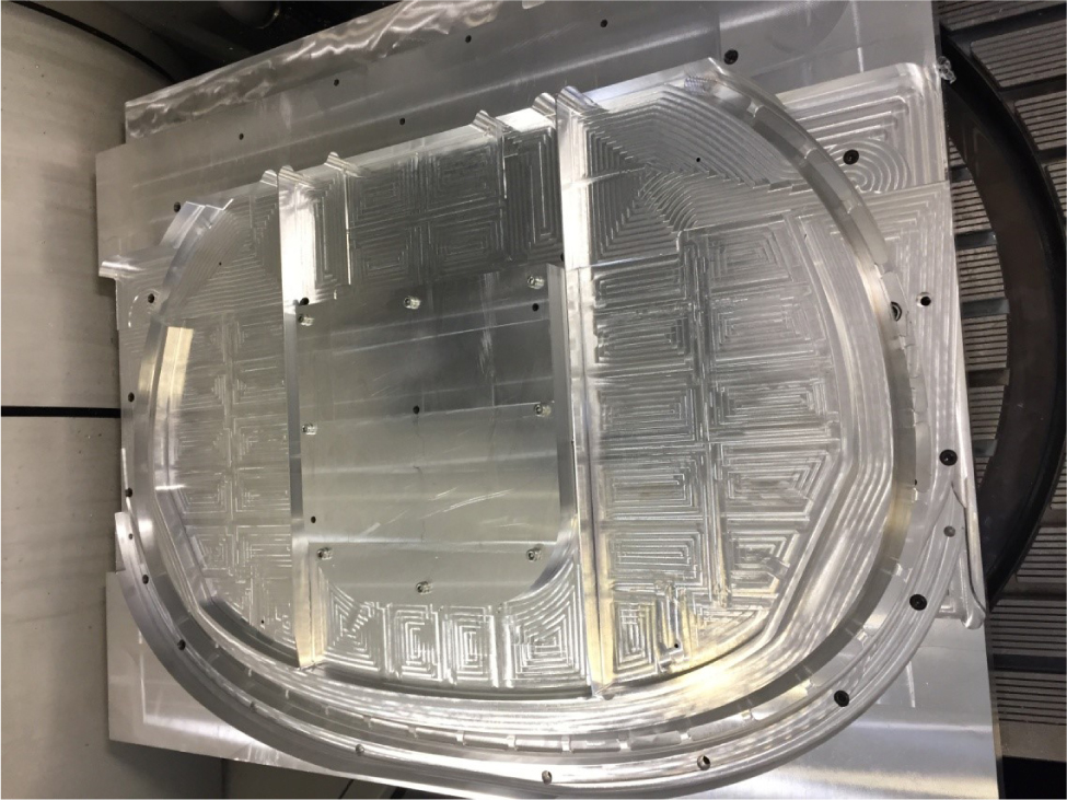
The frame mounting by technological bases and additional holes during the pocket machining
According to the assumptions of the construction documentation, the linear dimensions tolerance of the frame is determined by the norm BN-85/3813-79 – Deviations of non-tolerated dimensions, shape and location for aviation products. For the frame walls, the tolerances are:
g = 1-3mm, the deviations are: 0; 0.25 mm
For the rib height:
h = 20-25.8 mm, the deviations are: 0; –0.52 mm
For the overall dimensions:
1012 × 1354 mm, the dimensions are: 0; –2.6 mm
Mechanical machining of the frame was performed in two stages: pre-machining and finishing. A number of passes in all cases was determined by the wall dimensions and the axial cutting depth. The basic requirement in the machining process was to ensure as little deformation of the ribs as possible and also ensuring appropriate surface roughness during the finishing machining. In the machined frame, 2 mm finishing allowances were used for large face surfaces and about 0.2 mm on the ribs walls with a thickness of 1-3 mm. In order to reduce the wall deformation, the contact time between the tool and the workpiece had to be shortened. It was obtained by using high speed cutting (high tool rotational speeds). The subsequent treatment which ensured high machining precision of smooth frame walls (the height-to-thickness ratio was approximately 13) was to maintain a proper machining strategy. The most effective strategy was alternate pocket machining with the change of machining sides and with machining to the same levels in each pocket. During machining of thin walls it is recommended to mill in reverse.
For the most reasonable cutting parameters, shank cutters with sintered carbide pads were used and the variable depths and widths of the milled layer were also used. The parameters are presented in Table 2. The best results of the cutting process efficiency were obtained using the Φ16 mm cutter and the lowest surface roughness and waving were obtained using the Φ 8mm cutter.
The cutting parameters used during the frame machining
| No. | Cutter diameter Φ mm | Cutting speed vc m/min | Cutting depth ap mm | Cut layer width ae mm | Feed rate fz mm/tooth |
|---|---|---|---|---|---|
| 1. | 6 | 250 | 1 | 0.05-0.075 | 0.03 |
| 2. | 8 | 300 | 2 | 0.05-0.075 | 0.055 |
| 3. | 16 | 350 | 5 | 0.05-0.075 | 0.07 |
3 Results and discussion
It can be stated that the implemented technology can be used for thin-walled structures manufacturing where the chips mass can be up to 95% of the initial material. It should be emphasized that the frame weight is 3.85 kg. As a result of the machining, the frame compatible with the structural documentation was obtained (Figure 3).
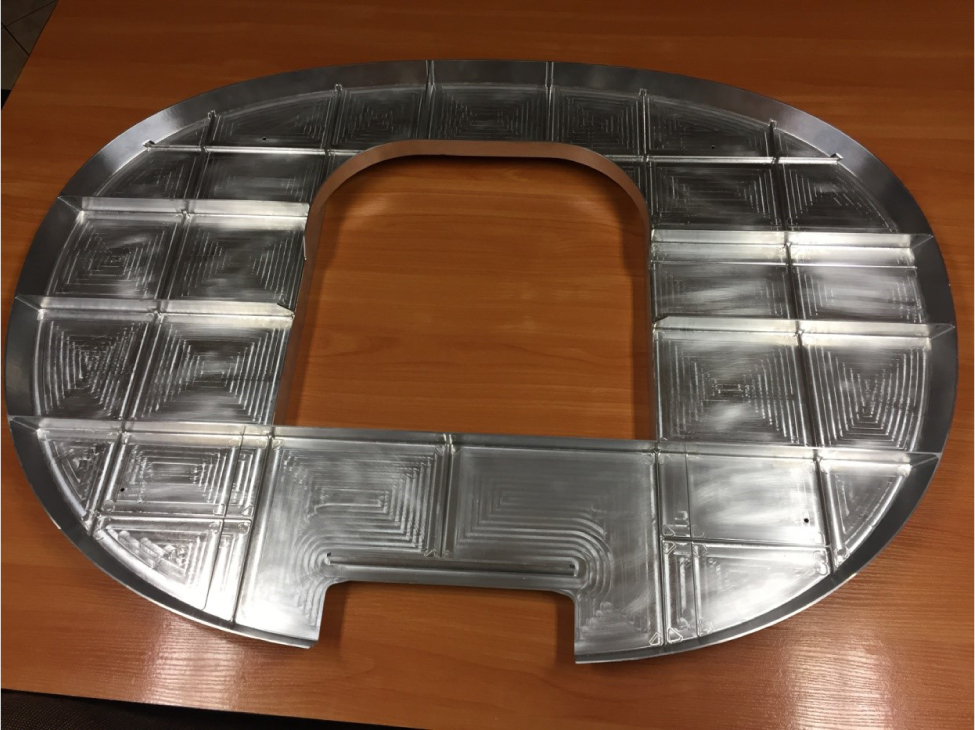
The finished frame after mechanical machining (shaping)
The weight of the finished frame was 3.15 kg and the weight of the initial material was 243 kg, so the product weight was 1.3% of the initial material. 98.7% of the semi-finished material was changed into chips. Therefore, the ”buy-to-fly” ratio (weight of the initial material to the weight of the final product) was 77.1. The maximum contact time between a cutter and a workpiece during the milling process was: a) t = 3, 75 * 10-3s; b) t = 6, 38 * 10–4s.
The frame was optically measured by the GOM scanner in order to verify its shape, dimensions, and spatial displacements (Figure 4, Figure 5). This research allowed to determine linear dimensions of the particular frame elements and to create digital and contour maps showing the frame stereometry. Those maps mostly allowed evaluation of the deformation potential of the large frame surface. The deformations can be caused by internal stresses generated in the structure during mechanical processing [2, 3]. The dimensions analysis shows that the deviations of the linear dimensions fall within the predicted tolerances. The block is mainly deformed towards the shorter axis of symmetry and the displacements are symmetrical towards the longer axis of symmetry. The highest relative displacement values are 0.57 mm. The GOM scanner ensures the precise measurements with a margin of error of +/– 0.25 mm. However, this method shows in a reliable way what deformations should be expected in the machining of products of a similar structure.
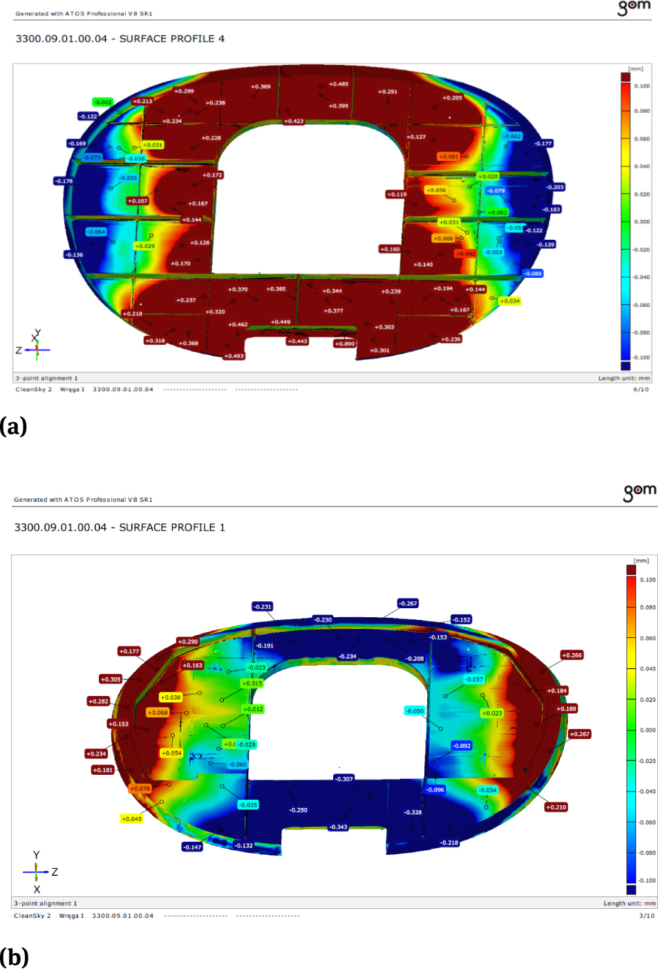
The maps of the linear dimensions and displacements of the frame elements after the mechanical machining: a) top side, b) bottom side
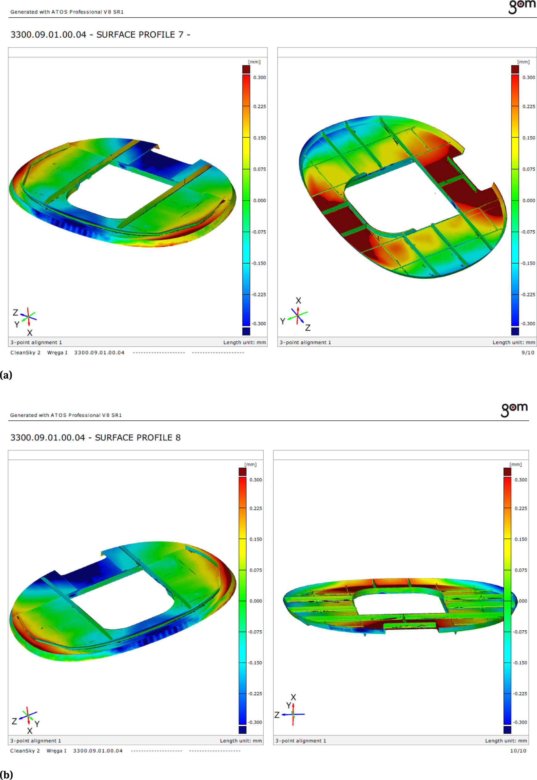
The maps of the linear dimensions and displacements of the frame elements after the mechanical machining
For a precise evaluation of the ribs’ wall thicknesses, which are the most significant when considering construction strength, they were measured using a micrometer. The measurements were done at the ribs’ points which were expected to be the most vulnerable to deformations during machining. The measurements were done at the base of the rib and at the top. The layout of the measurement points is presented in Figure 6, while the measurement results are presented in Table 3.
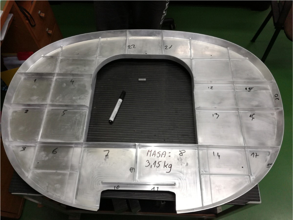
The measurement points layout (the part after finishing)
Thickness dimensions of the particular frame walls
| Point no. | Dimension at the base | Dimension at the top | Point no. | Dimension at the base | Dimension at the top | Point no. | Dimension at the base | Dimension at the top |
|---|---|---|---|---|---|---|---|---|
| 1. | 2.00 | 2.02 | 11 | 3.01 | 3.01 | 21 | 2.01 | 2.02 |
| 2. | 2.01 | 2.02 | 12 | 2.05 | 2.01 | 22 | 2.05 | 2.02 |
| 3. | 2.01 | 1.95 | 13 | 2.01 | 2.01 | 23 | 1.99 | 2.00 |
| 4. | 1.95 | 2.02 | 14 | 2.01 | 2.01 | 24 | 1.05 | - |
| 5. | 2.00 | 2.02 | 15 | 2.00 | 2.02 | 25 | 1.07 | - |
| 6. | 2.05 | 2.00 | 16 | 2.00 | 2.00 | 26 | 1.06 | - |
| 7. | 1.96 | 1.95 | 17 | 2.00 | 2.00 | 27 | 2.00 | 2.02 |
| 8. | 1.95 | 1.96 | 18 | 1.98 | - | 28 | 2.00 | 2.01 |
| 9. | 2.00 | 2.05 | 19 | 2.00 | - | 29 | 2.01 | 2.02 |
| 10. | 3.01 | 3.01 | 20 | 1.95 | - | 30 | 2.01 | 2.01 |
In order to estimate the shape, dimensions and spatial displacements of the frame as a finished subassembly, it was checked on a control device which is used to control the frames currently used in the aircraft (Figure 7). The research has proved that the frame dimensions fall within the tolerances predicted in the technical documentation. The dimensions also conformed to the norm BN-85/3813-79, which is used for verifying non-tolerated deviations, shape, and location for aviation products.
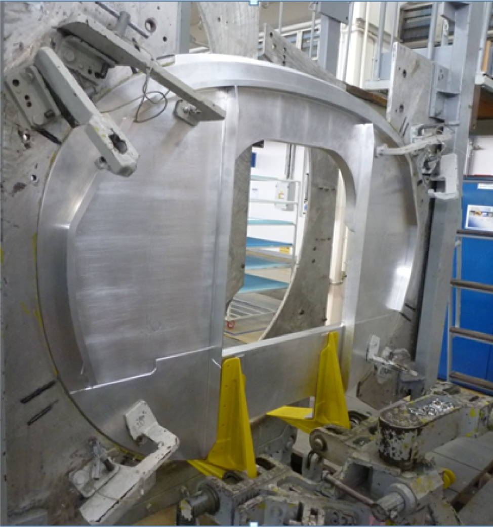
The finished frame mounted in the device used for checking the aircraft frames
4 Final remarks and conclusions
The use of High Speed Milling technology for machining of thin-walled aircraft frames is possible due to the precision of the workpiece and the machining capabilities of the 7075 aluminium alloys. Appropriate cutting parameter selection ensures good surface roughness and waviness.
In the case of the walls machining having a height-thickness ratio of less than 15, the influence of the structure deformation on the workpiece’s dimensional precision is not important and it falls within the tolerance of the milling machine. For larger walls slenderness, this influence starts to be visible and needs to be minimized by the cutting speed selection (feed rate, cutting depth).
Providing dimensional-shape precision during the machining requires an appropriate selection of the technological bases and the mounting method of the work-piece. In compound spatial structures some additional bases ensuring mounting stiffness should be implemented and then removed during the final operations.
The final HSM technology application allows the producer to reduce the workpiece machining time. The manufacturing time of the frame (including software preparation) is 320 hours. The frame manufacturing time can be reduced to 15 hours in the series production by using the proven control program and the experience gained during the prototype manufacturing. The roughing time of the frame is about 18 hours, and the finishing is about 5 hours, which overall takes about 23 hours to manufacture the frame using the HSM technology. When comparing the HSM method to conventional machining methods, it needs to take about 141 hours to manufacture the frame by conventional milling.
The completed part is an integral construction replacing the current methods of manufacturing the same element by plastic processing of individual parts (30 or more parts) and then joining them by fasteners. The overall manufacturing time of individual elements of the frame was more than 6 times more hours than the manufacturing time of the proposed HSM method. Simultaneously with the benefits resulting from the reduction of the manufacturing time of the frame, the benefit of the proposed technology is also the quality and accuracy of the manufacturing as well as the roughness class of the surfaces.
Acknowledgement
The works were carried out within the project “699757/SAT-AM” – Work programme topic: JTI-CS2-2015-CPW02-AIR-02-07. More Affordable Small Aircraft Manufacturing; Airframe itd. Grant Agreement No: CS2-AlR-GAM-2014-2015-01 (annex III) co-financed by Horizon 2020 Clean Sky 2.
Special thanks go to the teams from: Instytut Lotnictwa, SZEL-TECH Szeliga Grzegorz, Zakłady Lotnicze Margański&Mysłowski, PZL Mielec, CIRA, Eurotech, Metrol and Ultratech.
References
[1] Lundblad M., Influence of Cutting Tool Geometry on Residual Stress in the Workpiece, Proc. Third Wave AdvantEdge User’s Conferece, Atlanta, GA, Paper 7 (2002).Search in Google Scholar
[2] Shet C., Deng X., Residual Stresses and Strains in Orthogonal Metal Cutting, Int. J. Machine Tools Manuf., 43/6, 573-587, (2003).10.1016/S0890-6955(03)00018-XSearch in Google Scholar
[3] Shih A.J., Yang H.T.Y., Experimental and Finite Element Predictions of Residual Stresses Due to Orthogonal Metal Cutting, Int. J. Num. Meth. Eng., 36, 1487-1507 (1993).10.1002/nme.1620360905Search in Google Scholar
[4] Adamski W., Manufacturing development strategies in aviation industry, Advances in Manufacturing Science and Technology, Vol. 34, nr 3, 73-84 (2010).Search in Google Scholar
[5] Mativenga P.T., Hon K. K. B., An experimental study of cutting force in high speed end milling and implications for dynamic force modelling, Journal of Manufacturing Science and Engineering, 127, 2, 251-261 (2005).10.1115/1.1863254Search in Google Scholar
[6] Kuczmaszewski J., Pieśko P., Zawada-Michałowska M., Influence of Milling Strategies of Thin-walled Elements on Effectiveness of their Manufacturing, Procedia Engineering, 182:381-186 (2017).10.1016/j.proeng.2017.03.117Search in Google Scholar
© 2018 P. Bałon et al.
This work is licensed under the Creative Commons Attribution-NonCommercial-NoDerivatives 4.0 License.
Articles in the same Issue
- Regular Article
- Real-scale comparison between simple and composite raw sewage sampling
- 10.1515/eng-2018-0017
- The risks associated with falling parts of glazed facades in case of fire
- Implementation of high speed machining in thin-walled aircraft integral elements
- Evaluating structural crashworthiness and progressive failure of double hull tanker under accidental grounding: bottom raking case
- Influence of Silica (SiO2) Loading on the Thermal and Swelling Properties of Hydrogenated-Nitrile-Butadiene-Rubber/Silica (HNBR/Silica) Composites
- Statistical Variations and New Correlation Models to Predict the Mechanical Behavior and Ultimate Shear Strength of Gypsum Rock
- Analytic approximate solutions to the chemically reactive solute transfer problem with partial slip in the flow of a viscous fluid over an exponentially stretching sheet with suction/blowing
- Thermo-mechanical behavior simulation coupled with the hydrostatic-pressure-dependent grain-scale fission gas swelling calculation for a monolithic UMo fuel plate under heterogeneous neutron irradiation
- Optimal Auxiliary Functions Method for viscous flow due to a stretching surface with partial slip
- Vibrations Analysis of Rectangular Plates with Clamped Corners
- Evaluating Lean Performance of Indian Small and Medium Sized Enterprises in Automotive Sector
- FPGA–implementation of PID-controller by differential evolution optimization
- Thermal properties and morphology of polypropylene based on exfoliated graphite nanoplatelets/nanomagnesium oxide
- A computer-based renewable resource management system for a construction company
- Hygrothermal Aging of Amine Epoxy: Reversible Static and Fatigue Properties
- The selected roof covering technologies in the aspect of their life cycle costs
- Influence of insulated glass units thickness and weight reduction on their functional properties
- Structural analysis of conditions determining the selection of construction technology for structures in the centres of urban agglomerations
- Selection of the optimal solution of acoustic screens in a graphical interpretation of biplot and radar charts method
- Subsidy Risk Related to Construction Projects: Seeking Causes
- Multidimensional sensitivity study of the fuzzy risk assessment module in the life cycle of building objects
- Planning repetitive construction projects considering technological constraints
- Identification of risk investment using the risk matrix on railway facilities
- Comparison of energy parameters of a centrifugal pump with a multi-piped impeller in cooperation either with an annular channel and a spiral channel
- Influence of the contractor’s payment method on the economic effectiveness of the construction project from the contractor’s point of view
- Special Issue Automation in Finland
- Diagnostics and Identification of Injection Duration of Common Rail Diesel Injectors
- An advanced teaching scheme for integrating problem-based learning in control education
- A survey of telerobotic surface finishing
- Wireless Light-Weight IEC 61850 Based Loss of Mains Protection for Smart Grid
- Smart Adaptive Big Data Analysis with Advanced Deep Learning
- Topical Issue Desktop Grids for High Performance Computing
- A Bitslice Implementation of Anderson’s Attack on A5/1
- Efficient Redundancy Techniques in Cloud and Desktop Grid Systems using MAP/G/c-type Queues
- Templet Web: the use of volunteer computing approach in PaaS-style cloud
- Using virtualization to protect the proprietary material science applications in volunteer computing
- Parallel Processing of Images in Mobile Devices using BOINC
- “XANSONS for COD”: a new small BOINC project in crystallography
- Special Issue on Sustainable Energy, Engineering, Materials and Environment
- An experimental study on premixed CNG/H2/CO2 mixture flames
- Tidal current energy potential of Nalón river estuary assessment using a high precision flow model
- Special Spring Issue 2017
- Context Analysis of Customer Requests using a Hybrid Adaptive Neuro Fuzzy Inference System and Hidden Markov Models in the Natural Language Call Routing Problem
- Special Issue on Non-ferrous metals and minerals
- Study of strength properties of semi-finished products from economically alloyed high-strength aluminium-scandium alloys for application in automobile transport and shipbuilding
- Use of Humic Sorbent from Sapropel for Extraction of Palladium Ions from Chloride Solutions
- Topical Issue on Mathematical Modelling in Applied Sciences, II
- Numerical simulation of two-phase filtration in the near well bore zone
- Calculation of 3D Coordinates of a Point on the Basis of a Stereoscopic System
- The model of encryption algorithm based on non-positional polynomial notations and constructed on an SP-network
- A computational algorithm and the method of determining the temperature field along the length of the rod of variable cross section
- ICEUBI2017 - International Congress on Engineering-A Vision for the Future
- Use of condensed water from air conditioning systems
- Development of a 4 stroke spark ignition opposed piston engine
- Development of a Coreless Permanent Magnet Synchronous Motor for a Battery Electric Shell Eco Marathon Prototype Vehicle
- Removal of Cr, Cu and Zn from liquid effluents using the fine component of granitic residual soils
- A fuzzy reasoning approach to assess innovation risk in ecosystems
- Special Issue SEALCONF 2018
- Brush seal with thermo-regulating bimetal elements
- The CFD simulation of the flow structure in the sewage pump
- The investigation of the cavitation processes in the radial labyrinth pump
- Testing of the gaskets at liquid nitrogen and ambient temperature
- Probabilistic Approach to Determination of Dynamic Characteristics of Automatic Balancing Device
- The design method of rubber-metallic expansion joint
- The Specific Features of High-Velocity Magnetic Fluid Sealing Complexes
- Effect of contact pressure and sliding speed on the friction of polyurethane elastomer (EPUR) during sliding on steel under water wetting conditions
- Special Issue on Advance Material
- Effect of thermo-mechanical parameters on the mechanical properties of Eurofer97 steel for nuclear applications
- Failure prediction of axi-symmetric cup in deep drawing and expansion processes
- Characterization of cement composites based on recycled cellulosic waste paper fibres
- Innovative Soft Magnetic Composite Materials: Evaluation of magnetic and mechanical properties
- Statistical modelling of recrystallization and grain growth phenomena in stainless steels: effect of initial grain size distribution
- Annealing effect on microstructure and mechanical properties of Cu-Al alloy subjected to Cryo-ECAP
- Influence of heat treatment on corrosion resistance of Mg-Al-Zn alloy processed by severe plastic deformation
- The mechanical properties of OFHC copper and CuCrZr alloys after asymmetric rolling at ambient and cryogenic temperatures