A mechanical and microstructural investigation of friction stir processed AZ31B Mg alloy-SiC composites
-
Kanif Markad
 ,
Kishan Fuse
,
Kishan Fuse

Abstract
Friction stir processing (FSP) has emerged as an effective technique for enhancing the mechanical and microstructural properties of metal matrix composites. This study investigates the influence of FSP parameters on the mechanical characteristics and microstructure of AZ31B magnesium alloy reinforced with silicon carbide particles of size APS < 80 nm. The method employed here is a hole method for reinforcement and designed with an L9 orthogonal array to analyze the effects of tool geometry, rotational speed, traverse speed, and hole diameter. The experimental findings indicate that a cylindrical threaded tool pin profile, a 0.8-mm hole diameter, a rotational speed of 765 revolutions per minute, and a traverse speed of 31.5 mm/min resulted in the most optimal combination of mechanical properties, including improved tensile strength, micro-hardness, and elongation. Microstructural analysis revealed a uniform distribution of SiC particles, leading to grain refinement and enhanced material performance. These results demonstrate that FSP is a sustainable approach for fabricating high-performance magnesium-based composites, making them suitable for applications in aerospace, automotive, and biomedical industries.
1 Introduction
Magnesium and its alloys have become a remarkable material from aluminum (Al) plus steel by a density of 40 and 78% lower, respectively, and have become increasingly important substitute for aluminum plus steel alloys. Magnesium alloys reflect a synergistic combination of advantageous attributes, including as good as comparable strength, exceptional formability, superficial castability, effective machinability, recyclability, noticeable damping characterization, and a remarkable weight-to-stiffness ratio and weight-to-strength ratio, placing them as challenging competitors to replace aluminum alloys across a diverse array of industrial and commercial applications [1,2,3,4]. Over the course of periods, the development of magnesium alloys can be divided into four discrete stages: an initial stage of 80 years of laboratory research, next 40 years phase of semi-technical advancement, and next 30 years of solid commercial and industrial adoption, concluding in their various application across diverse domains, including pharmaceuticals, medical, and scientific technology, despite integral challenges [5]. As a leading global producer, China significantly shapes the supply chain and market dynamics of magnesium alloys [6,7].
Magnesium alloys and surface composites are produced through a range of fabrication processes, showcasing their versatility and ability to cater to diverse application requirements. However, achieving the desired dispersion of reinforcing particles in surface composites using certain conventional methods has been recognized as a challenging task [8,9]. This gives the platform for the importance of this issue over the last decade; several attempts have been made available to inculcate these limitations. Conventional surface treatments had been engaged to distribute ceramic base particles on metallic top surfaces, but with limited success [10,11,12,13,14]. The fabrication of surface composites has been hampered by the formation of undesirable phases, particularly in liquid processing methods [15,16,17].
Magnesium alloy surface composite fabrication involves several methodologies, which can be generally categorized as liquid processing, vapor processing, and solid processing. In liquid processing techniques, magnesium alloys undergo treatment in their molten state, encompassing squeeze infiltration, where pressure is applied to force molten metal into a preform. Other liquid processing techniques include stir casting, characterized by the mechanical incorporation of reinforcements into the molten metal, and melt deposition, which employs a molten matrix to deposit reinforcements onto a surface. Vapor processing, on the contrary, involves the deposition of materials onto a magnesium substrate from a gaseous state, including chemical vapor deposition, where a chemical reaction produces the desired coating, and physical vapor deposition, which typically employs techniques such as sputtering or evaporation to deposit thin films. Solid processing encompasses methods that avoid melting the base material, such as powder metallurgy, where powdered substances are compacted and sintered; friction stir processing (FSP), a solid-state method employing a rotating tool to mechanically integrate reinforcement particles into the substrate surface; and diffusion bonding, which joins materials at high temperatures under pressure without inducing melting [18].
The effectiveness of surface modification techniques has been widely studied and documented in the literature for the FSP method to modify the surface of composites. The analysis of experimental results for plasma spray coatings using statistical techniques has shown the potential of these methods to improve the performance of industrial components [19]. Furthermore, the tribological corrosion behavior of titanium alloy components has been investigated, demonstrating the benefits of surface modification in biomedical applications [20]. Surface modification methods play a vital role in the development and optimization of materials for various industrial and biomedical applications. By tailoring the surface properties, these techniques can enhance the reliability, efficiency, and functionality of critical components, contributing to the overall progress and competitiveness of modern industries.
Additionally, the microstructural as well as mechanical properties of fabricated surface composites have been suboptimal. To address these, a novel method known as FSP was successfully implemented. In 1991, friction stir welding process, which was developed by the Institute of Welding in the United Kingdom, was further developed for a new approach as FSP [21]. In FSP, process parameters are optimized to modify the surface of the material, which leads to microstructural changes in the desired zone. This new approach of surface modification has led to a new platform researchers to think about these as new challenges.
del Valle et al. [22] and Zang et al. [23] explored the impacts of FSP on AZ31 series magnesium alloys, revealing substantial grain refinement. Specifically, Del Valle et al. attained a grain size approaching 0.5 μm, which facilitated superplasticity at elevated temperatures. Likewise, Zang et al. noted grain size fluctuations from 10.4 to 13.6 μm over multiple FSP passes, demonstrating the technique’s capacity to regulate microstructural development. Raja et al. [24] and MD and Panigrahi et al. [25] evaluated the effects of FSP on other magnesium alloys, including AZ91 and QE22. Raja et al. reported a significant reduction in the dendritic alpha-phase magnesium microstructure from an initial size of 100 μm to just 2 μm. Additionally, Panigrahi examined the high-temperature tensile deformation behavior of QE22 alloys, highlighting the presence of dual-mode superplasticity. Numerous studies have demonstrated the remarkable enhancements in mechanical properties achievable through FSP. Singh Sidhu et al. [26] reported substantial gains in tensile strength and creep resistance for AZ91 magnesium alloys at ambient temperatures, with these improvements further amplified at elevated temperatures. Similarly, Shang et al. [27] observed that the introduction of extension twins in AZ31 alloys led to a marked rise in yield strength, from 96 to 122 MPa. Furthermore, Patel et al. [28] were able to realize an 80% enhancement in hardness and a 24% improvement in tensile strength by incorporating a copper backing plate during the FSP process.
Magnesium alloys have become widely adopted across diverse industrial sectors due to their advantageous properties, including low density, high strength, and excellent mechanical performance. They find essential applications in automotive, aerospace, electronics, and textile industries, utilized in components such as braking system brackets, transmission housings, landing gear, rotor fittings, and computer casings. The higher heat dissipation, electromagnetic shielding, and minimal radio frequency snooping characteristics of magnesium alloys make them invaluable in electronic applications, while their biocompatibility supports their use in biomedical devices like cardiovascular stents and orthopedic implants. However, certain limitations, including restricted strength, plasticity, and high degradation rates, have hindered their more widespread adoption, particularly in large-scale applications. Nonetheless, surface coatings and reinforcement techniques have been employed to improve the properties of magnesium alloys, enabling them to compete effectively with traditional materials in automotive and structural applications [18].
FSP has emerged as a promising surface modification technique for composite materials, offering a range of benefits compared to traditional fusion-based welding methods. This innovative process has the potential to improve the mechanical properties, microstructural characteristics, and overall performance of composite materials, making it a valuable and important tool in the field of sustainable manufacturing. One of the key advantages of FSP for composites is its ability to promote a most possible uniform distribution of reinforcement particles within the matrix material [29]. This is particularly important for magnesium-based composites, where the even dispersal of hard ceramic particles can significantly improve hardness and wear resistance, making them more applicable for various aerospace, automotive, and marine applications [30].
So from the literature survey, it is observed that sufficient work was performed on aluminum-based composites with the friction stir process with different particle reinforcement in the hole method. So, it becomes mandatory to work on magnesium-based alloy material as it possesses less density than other matrix materials and that is the reason the chosen material will find application in variety of fields. The present investigation examines the processing of 6 mm-thick magnesium alloy-based metal matrix composite plates through the application of FSP. The objective of the present work is to fabricate MMC-based magnesium alloys for subsequent surface modification using FSP. To fabricate and achieve, L9 orthogonal array with four factors and three levels is employed during the FSP process [31]. The study investigates essential mechanical properties, such as UTS, yield strength, and microhardness. The microstructural characteristics were observed and recorded using both optical microscopy and scanning electron microscopy (SEM) to gain deeper insights into the surface composite [32]. This investigation will provide an outlook to get full-depth overview of the microstructure and the effect of the proposed approach on the surface composite.
2 Experimental details
Experimental details cover the procurement of material for experimentation/analysis and general methodology adopted for sample preparation from the studied literature.
2.1 Material procurement
The materials utilized in this investigation were carefully selected to ensure compatibility with FSP. The magnesium alloy AZ31B, renowned for its excellent mechanical properties and corrosion resistance, was obtained in sheet form with a thickness of 6 mm. These sheets were sourced from a certified supplier, guaranteeing conformity to ASTM standards and verification of the chemical composition and mechanical properties through material test certificates.
Furthermore, silicon carbide reinforcement particles were chosen, due to their high hardness and wear resistance [33,34]. These particles were procured in powder form with an average nano-particle size APS < 80 nm, CAS 409-21-2, and a purity of 99% from certified supplier DP Analytics, Ahmedabad.
2.2 Methodology for sample preparation
This current study presents a comprehensive investigation of the mechanical properties of magnesium alloy (Mg alloy) and SiC reinforcement surface composites, yielding valuable insights into their strengths and hardness. This information can guide the development of materials optimized for applications requiring outstanding mechanical properties. This work aims to fabricate a surface composite of magnesium alloy and SiC reinforcement particles using the FSP for the zigzag hole method. Additionally, in this work, it develops the state of the art for manufacturing surface composites, particularly in the form of integrating nano-particles reinforcement, which will lead to surface modification with more effective mechanical properties and better-quality performance.
As shown in Figure 1, sample square plate of aeroplane grade AZ31B of size 100 mm × 100 mm was prepared from wire cut EDM of thickness 6 mm. In a base square plate, zig zag circular holes of depth 4.5 mm with varying diameter hole are prepared as observed in Figure 2. For further analysis, the diameter of the circular hole is varied as 0.8, 1.2, and 1.6 mm [35].
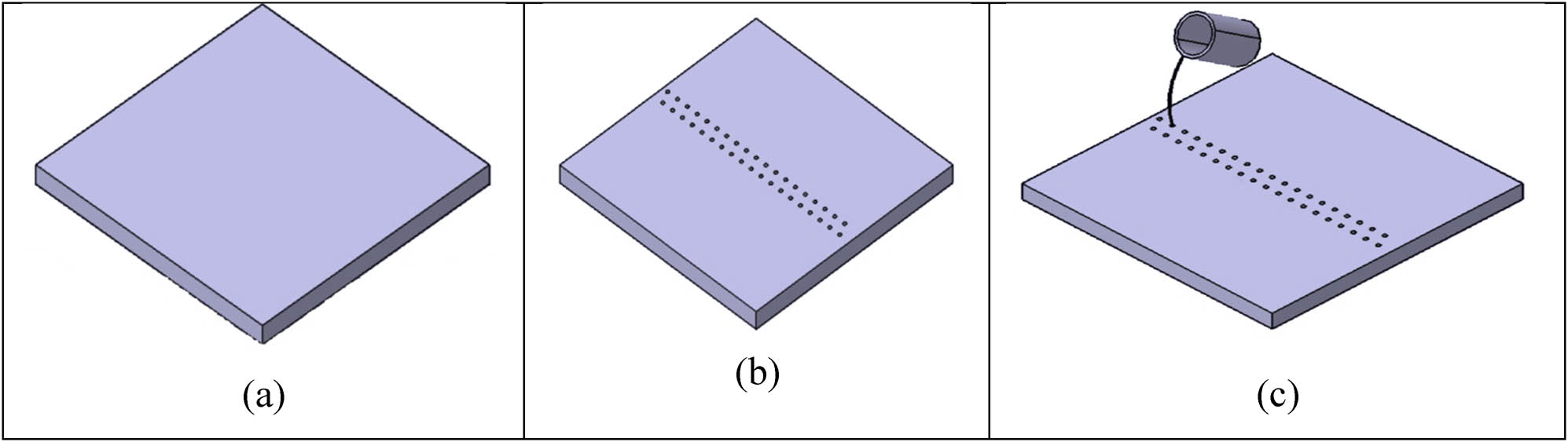
Specimen diagram: (a) AZ31B plate (100 mm × 100 mm × 6 mm), (b) AZ31B Plate with a zig zag hole pattern of 1.6 mm diameter, and (c) zig zag holes filling with SiC particles.
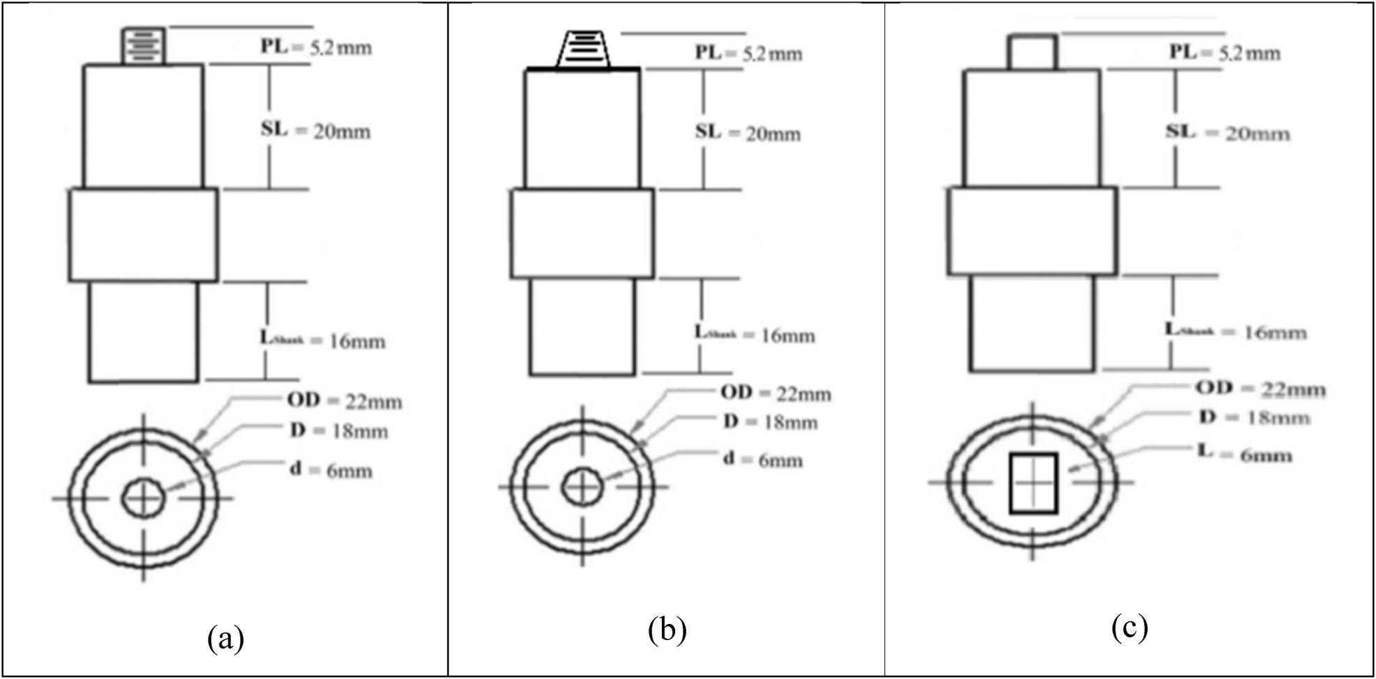
Tool pin profile: (a) cylindrical threaded, (b) taper threaded, (c) square headed.
Additionally, custom-fabricated FSP tools were constructed from high-strength H13 tool steel to accommodate three distinct geometries: square, tapered, and tapered threaded (TT) as shown in Figure 2. These tools were manufactured at a specialized machining facility to ensure precise dimensions and optimal performance during the processing phase. The selected materials and tools were thoroughly prepared and characterized to meet the specific requirements of the experimental setup.
2.3 Design of experiment
A total of nine experiments were conducted using an L9 orthogonal array with four factors (tool geometry, rotational speed, traverse speed, and hole diameter) and for each factor three levels of variations is done. The factors and their levels are as follows and tabulated in Table 1.
Tool geometry: square, cylindrical threaded (CT), and TT
Rotational speed: 545, 765, and 1,070 rpm
Traverse speed: 20, 31.5, and 50 mm/min
Hole diameter: 0.8, 1.2, and 1.6 mm
L9 orthogonal array for hole method
| Exp. No | Tool rotation speed (RPM) | Traverse speed (mm/min) | Hole diameter (mm) | Tool profile |
|---|---|---|---|---|
| S10 | 545 | 20 | 0.8 | Tapered threaded |
| S11 | 545 | 31.5 | 1.2 | Square head |
| S12 | 545 | 50 | 1.6 | Cylindrical threaded |
| S13 | 765 | 20 | 1.2 | Cylindrical threaded |
| S14 | 765 | 31.5 | 1.6 | Tapered threaded |
| S15 | 765 | 50 | 0.8 | Square head |
| S16 | 1,070 | 20 | 1.6 | Square head |
| S17 | 1,070 | 31.5 | 0.8 | Cylindrical threaded |
| S18 | 1,070 | 50 | 1.2 | Tapered threaded |
The hole depth was maintained at a constant 4.5 mm for all experiments.
The specimens were prepared by cutting the processed plates into appropriate sizes for various characterization tests, including tensile, hardness, and microstructural analysis. The mechanical properties, such as tensile strength, yield strength, and elongation, were evaluated using a universal testing machine. Vickers hardness measurements were carried out on the surface of the composites. Microstructural analysis was performed using an optical microscope and a scanning electron microscope to examine the distribution and dispersion of the SiC reinforcement in the Mg alloy matrix.
2.4 Material characterization
Various mechanical characterizations were performed in the present study to analyze the effect of variation in various process parameters. Uniaxial tensile tests were conducted to determine the mechanical properties like yield stress, ultimate tensile stress, and elongation of the surface composite as per ASTM E8-E8M [36] on the samples with the dimensions: 100 mm × 10 mm × 6 mm. The samples were analyzed on a universal testing machine (FSAM-100, HTTC/M02, M/C NO. 201505) at Hertz testing and training center, Ahmedabad, with a capacity of 100 KN with a test speed of 1 mm/min. The harness of the Mg alloy AZ31B and SiC reinforced surface composite was performed on Vicker’s harness testing machine as per ASTM E92-17 [37] with the dimensions of 30 mm × 3 mm × 6 mm. Comprehensive microstructural analysis of Mg alloy and SiC reinforcement surface composites, employing techniques like optical microscopy and field-emission SEM, provides valuable insights into the distribution and alignment of the nanoparticles within the processed region. This knowledge is vital for evaluating the quality of Mg alloy and SiC reinforcement surface composites and ensuring the effective dispersion of the nano-scale reinforcements.
3 Results and discussion
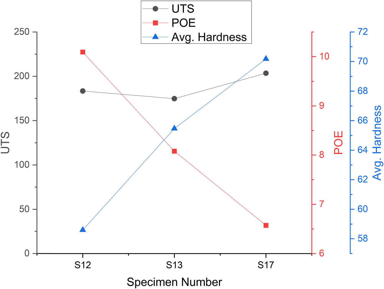
This section investigates the influence of process variables, such as rotational speed, traverse speed, hole diameter, and tool pin profile, on the mechanical characteristics, encompassing yield strength, ultimate tensile strength (UTS), percentage elongation, and hardness. The observed variations across different specimens are analyzed to identify the optimal conditions that enable enhanced material performance.
3.1 Effect of tool rotation speed
The rotational speed of tool significantly impacts on the heat generation, material flow, and mechanical characteristics during FSP. Lower rotational speed produces insufficient heat, leading to poor bonding, while excessive speeds can cause overheating, grain growth, and reduced strength. The mechanical properties of the Mg alloy, as processed at various tool rotational speeds, are presented in Tables 2–4, with their graphical representations depicted in Figures 3–5.
Mechanical properties at 545 RPM tool rotational speed
| Specimen number | UTS (MPa) | POE (%) | Avg. hardness (HV) |
|---|---|---|---|
| S10 | 198.73 | 8.64 | 67.55 |
| S11 | 159.18 | 6.35 | 59.87 |
| S12 | 183.50 | 10.09 | 58.60 |
Mechanical properties at 765 RPM tool rotational speed
| Specimen number | UTS (MPa) | POE (%) | Avg. hardness (HV) |
|---|---|---|---|
| S13 | 174.82 | 8.08 | 65.46 |
| S14 | 170.33 | 5.8 | 64.02 |
| S15 | 205.26 | 11.12 | 56.09 |
Mechanical properties at 1,070 RPM tool rotational speed
| Specimen number | UTS (MPa) | POE (%) | Avg. hardness (HV) |
|---|---|---|---|
| S16 | 145.62 | 3.45 | 86.83 |
| S17 | 203.54 | 6.57 | 70.18 |
| S18 | 112.73 | 3.84 | 64.62 |
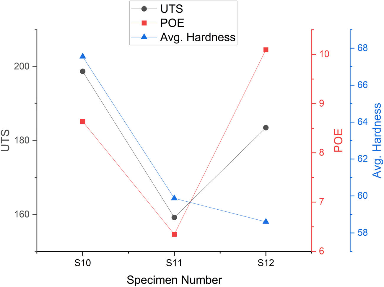
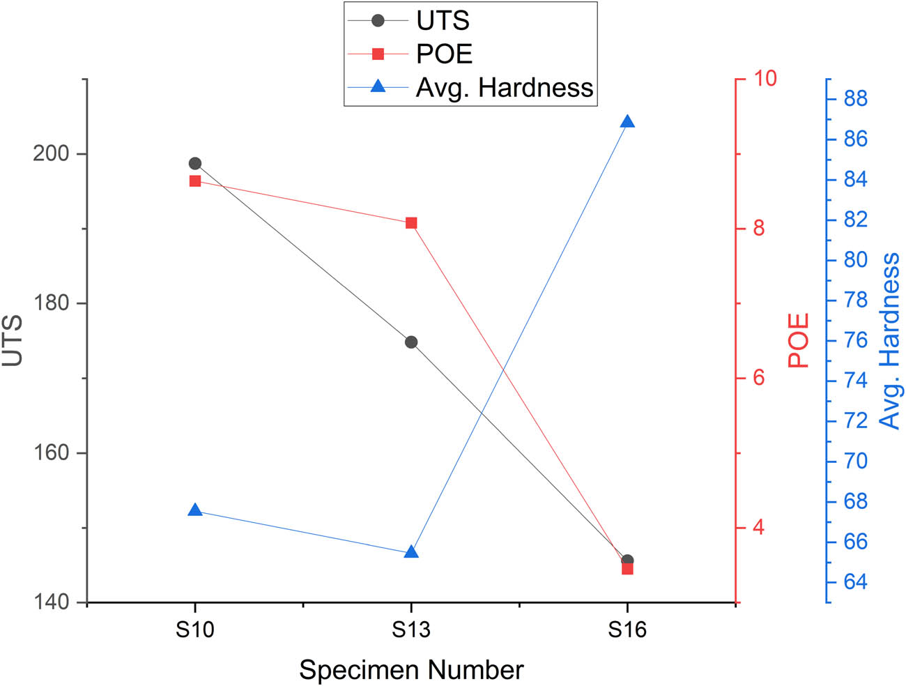
Graphical representation of mechanical properties at a 545 RPM tool rotational speed.
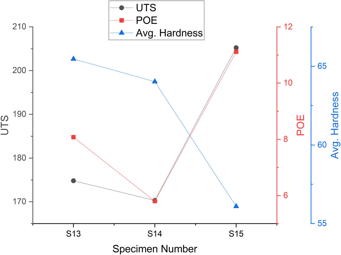
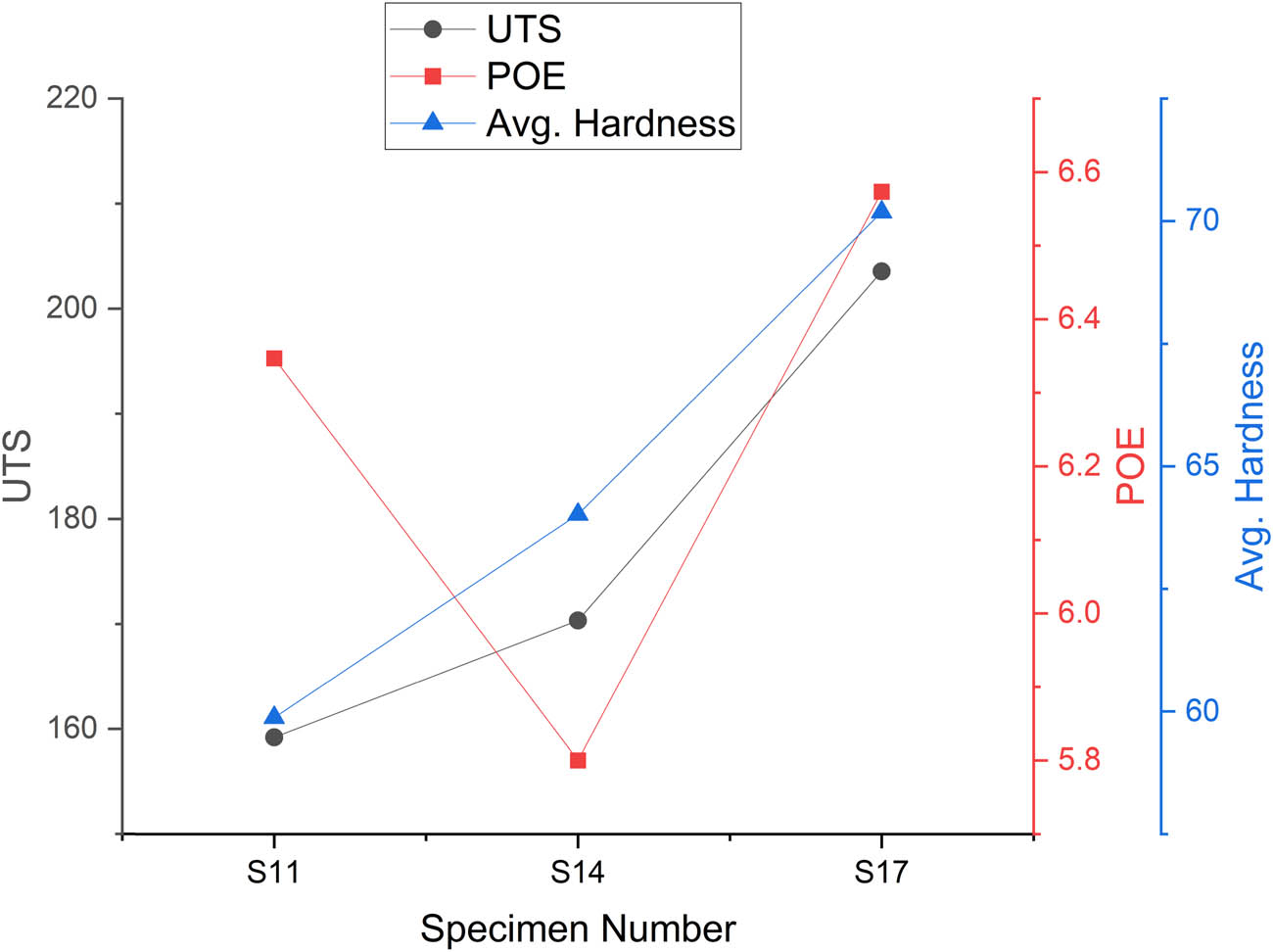
Graphical representation of the mechanical properties at 765 RPM tool rotational speed.

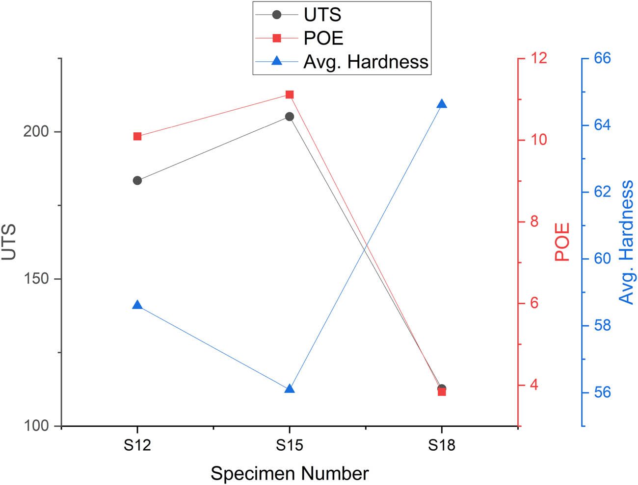
Graphical representation of the mechanical properties at 1,070 RPM tool rotational speed.
3.1.1 Effect of tool rotational speed 545 RPM
At a rotational speed of 545 RPM, the test results exhibited variations in the UTS across the specimens. Specimen S10 registered the highest UTS at 198.73 MPa, followed by S12 at 183.50 MPa, while S11 had the lowest value at 159.18 MPa. This suggests that the lower rotational speed facilitated a moderate heat input, which promoted proper grain refinement and maintained the overall tensile strength. It is observed that the UTS of the S10 sample is around 25% better than S11, while 8% better than that of sample S12. The percentage of elongation (POE) measurements showed the highest elongation of 10.09% in specimen S12, indicating better ductility due to the sufficient heat generation and plastic deformation.
The S10 sample exhibits 12.8 and 15.26% greater hardness values than the S11 and S12 samples, respectively. The moderate hardness observed at this rotational speed implies that the grain size and structural integrity were appropriately maintained.
In summary, the UTS varied between 159.18 and 198.73 MPa, with an average hardness ranging from 58.60 to 67.55. The highest elongation of 10.09% was observed in S12, suggesting improved ductility. These findings indicate that at the lower rotational speeds, the reduced heat generation allowed for better material flow, ultimately preserving the tensile strength.
3.1.2 Effect of tool rotational speed 765 RPM
The UTS of the S15 sample is better by 17 and 20.5% than the S13 and S14 samples. Similarly, POE is an indication of improved ductility, and with S15, it is 37 and 91% higher than S13 and S14 samples, respectively. But the hardness value was critically reduced by 14 and 12%, respectively, than the S13 and S14 samples.
The hardness values slightly decreased, with S15 showing a value of 56.09, likely due to a better balance of heat input and cooling rates. The increased UTS up to 205.26 MPa, combined with the relatively lower hardness values, suggests a trade-off between strength and ductility, and the moderate rotational speed of 765 RPM appears to enhance the stirring effect, leading to a more uniform grain distribution and improved overall mechanical properties.
3.1.3 Effect of tool rotational speed 1,070 RPM
At a rotational speed of 1,070 RPM, the mechanical properties exhibited a mixed response. In the UTS, the 39% improvement was noted in S17 compared with the S16 specimen, whereas in the S18 specimen that increment is 80% as that of the S17 specimen, suggesting that this speed facilitated some degree of grain refinement and material mixing.
However, specimen S18 recorded a notably lower UTS of 112.73 MPa, indicating that the excessive heat generation at this high rotational speed led to material softening. Similarly, the percent of elongation data shows that S17 had a moderate elongation of 6.57%, while specimens S16 and S18 exhibited much lower values of 3.45 and 3.84%, respectively, pointing to embrittlement of the material due to high-speed processing.
The findings suggest that increasing the rotational speed initially enhances the UTS and percent of elongation up to an optimal level, but further increases lead to material degradation due to excessive heat input. The maximum UTS were recorded at 765 RPM, while the highest hardness values were observed at 1,070 RPM, likely due to rapid cooling effects. Increasing the rotational speed improves heat generation and material flow, but beyond a certain point, excessive heat results in grain coarsening, which reduces the overall strength. The excessive heat input at 1,070 RPM appears to have caused material softening, leading to a decrease in UTS. The intermediate rotational speed of 765 RPM appears to provide an optimal balance between heat generation and material mixing, resulting in improved mechanical properties. In summary, higher rotational speeds enhance UTS and POE up to an optimal point, after which excessive heat generation at 1,070 RPM reduces UTS and ductility while increasing hardness due to grain coarsening.
3.2 Effect of feed rate
Feed rate is a crucial parameter that governs the strain rate and heat input during the process. Lower feed rates facilitate improved material bonding, but may also lead to excessive heat generation. Conversely, higher feed rates can result in insufficient heat input, ultimately causing defects. The mechanical characteristics associated with varying feed rates are presented in the tabular formats of Tables 5–7, and their corresponding graphical representations are depicted in Figures 6–8.
Mechanical properties at 20 mm/min feed rate
| Specimen number | UTS (MPa) | POE (%) | Avg. hardness (HV) |
|---|---|---|---|
| S10 | 198.73 | 8.64 | 67.55 |
| S13 | 174.82 | 8.08 | 65.46 |
| S16 | 145.62 | 3.45 | 86.83 |
Mechanical properties at 31.5 mm/min feed rate
| Specimen number | UTS (MPa) | POE (%) | Avg. hardness (HV) |
|---|---|---|---|
| S11 | 159.18 | 6.35 | 59.87 |
| S14 | 170.33 | 5.80 | 64.02 |
| S17 | 203.54 | 6.57 | 70.18 |
Mechanical properties at 50 mm/min feed rate
| Specimen number | UTS (MPa) | POE (%) | Avg. hardness (HV) |
|---|---|---|---|
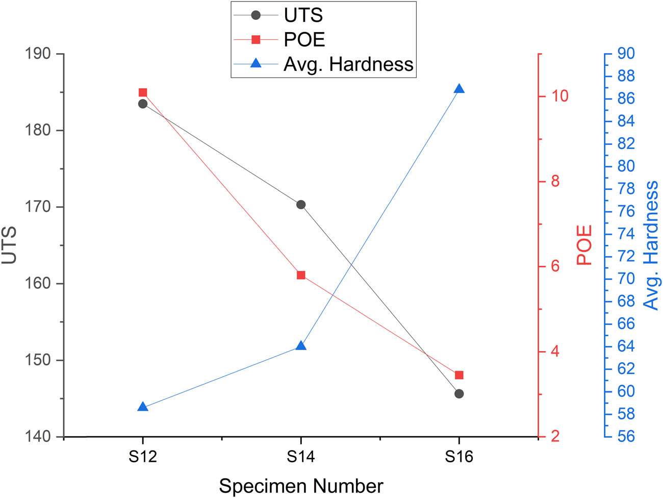
| S12 | 183.50 | 10.09 | 58.60 |
| S15 | 205.26 | 11.12 | 56.09 |
| S18 | 112.73 | 3.84 | 64.62 |
Graphical representation of mechanical properties at 20 mm/min feed rate.
Graphical representation of the mechanical properties at 31.5 mm/min feed rate.
Graphical representation of the mechanical properties at 50 mm/min feed rate.
3.2.1 Effect of feed rate 20 mm/min
At a feed rate of 20 mm/min, the test results showed the highest UTS of specimen S10. The UTS of sample S10 is 13 and 36% greater than that of S13 and S16 samples, respectively, indicating a well-consolidated microstructure
The highest hardness value of 86.83 was measured in S16, suggesting work hardening effects from the slow feed rate. Notably, S10 had the highest UTS of 198.73 MPa with a moderate hardness of 67.55, whereas S16 at the same feed rate showed the highest hardness of 86.83, indicating a localized strengthening effect. The lower feed rate of 20 mm/min allowed for sufficient heat input and material consolidation, improving the overall mechanical strength of the Mg alloy.
3.2.2 Effect of feed rate 31.5 mm/min
At a feed rate of 31.5 mm/min, the data exhibited better mechanical characteristics. The highest UTS was observed in specimen S17, indicating that this feed rate facilitated optimal heat input and material flow for improved consolidation. The UTS of sample S17 is higher by 28 and 19% as compared to S11 and S14, respectively. The same case is observed with POE also. The POE showed a moderate value of 6.57%, suggesting a balanced trade-off between strength and ductility. The POE of sample S17 is higher by 3.5 and 13% as compared to S11 and S14, respectively.
The hardness value for S17 was 70.18, confirming a moderate and well-balanced hardness level. Across the specimens tested at 31.5 mm/min, the UTS remained relatively stable, ranging from 159.18 to 203.54 MPa, further corroborating the balanced heat generation and material flow characteristics at this feed rate, which resulted in enhanced overall mechanical properties.
3.2.3 Effect of feed rate 50 mm/min
At a feed rate of 50 mm/min, the results exhibited a mixed response. The highest UTS of 205.26 MPa was observed in specimen S15, indicating that this feed rate facilitated optimal material consolidation and flow. The UTS of sample S15 is higher by 12 and 82% as compared to S12 and S18 samples, respectively.
However, specimen S18 recorded notably lower UTS 82 and 63% as compared to S15 and S12 samples, suggesting that the excessive feed rate led to inconsistencies in the mechanical properties. This observation suggests that high feed rates can result in uneven material properties.
The findings suggest that a feed rate of 31.5 mm/min provided the optimal balance among the mechanical properties, exhibiting the best combination of UTS, percent of elongation, and hardness. Lower feed rates resulted in higher hardness values, indicating significant work hardening, but reduced elongation. Conversely, higher feed rates of 50 mm/min led to the highest UTS values, but also introduced inconsistencies in the mechanical properties. This is likely due to the feed rate’s influence on material plasticization and consolidation – lower rates allow for better consolidation, while higher rates can cause defects like voids and incomplete fusion, ultimately reducing the overall strength of the material.
3.3 Effect of hole diameter
The hole diameter has a significant influence on the material flow and distribution of reinforcements, which in turn impact the mechanical characteristics of the material. The findings for various hole diameters are presented in Tables 8–10, accompanied by their corresponding graphical representations in Figures 9–11.
Mechanical properties at 0.8 mm hole diameter
| Specimen number | UTS (MPa) | POE (%) | Avg. hardness (HV) |
|---|---|---|---|
| S10 | 198.73 | 8.64 | 67.55 |
| S15 | 205.26 | 11.12 | 56.09 |
| S17 | 203.54 | 6.57 | 70.18 |
Mechanical properties at 1.2 mm hole diameter
| Specimen number | UTS (MPa) | POE (%) | Avg. hardness (HV) |
|---|---|---|---|
| S11 | 159.18 | 6.35 | 59.87 |
| S13 | 174.82 | 8.08 | 65.46 |
| S18 | 112.73 | 3.84 | 64.62 |
Mechanical properties at 1.6 mm hole diameter
| Specimen number | UTS (MPa) | POE (%) | Avg. hardness (HV) |
|---|---|---|---|
| S12 | 183.50 | 10.09 | 58.60 |
| S14 | 170.33 | 5.80 | 64.02 |
| S16 | 145.62 | 3.45 | 86.83 |
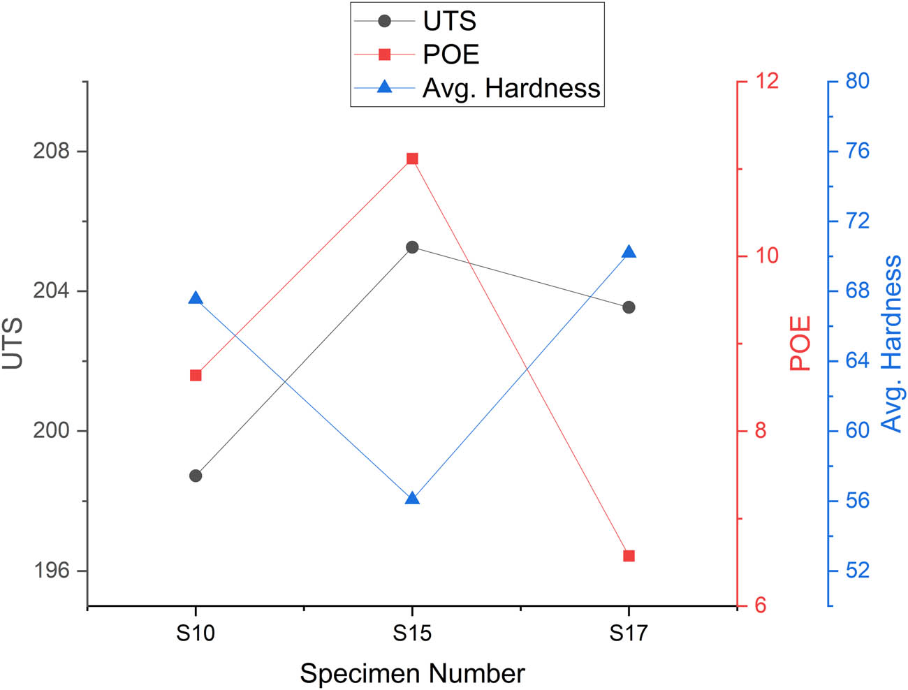
Graphical representation of the mechanical properties at 0.8 mm hole diameter.
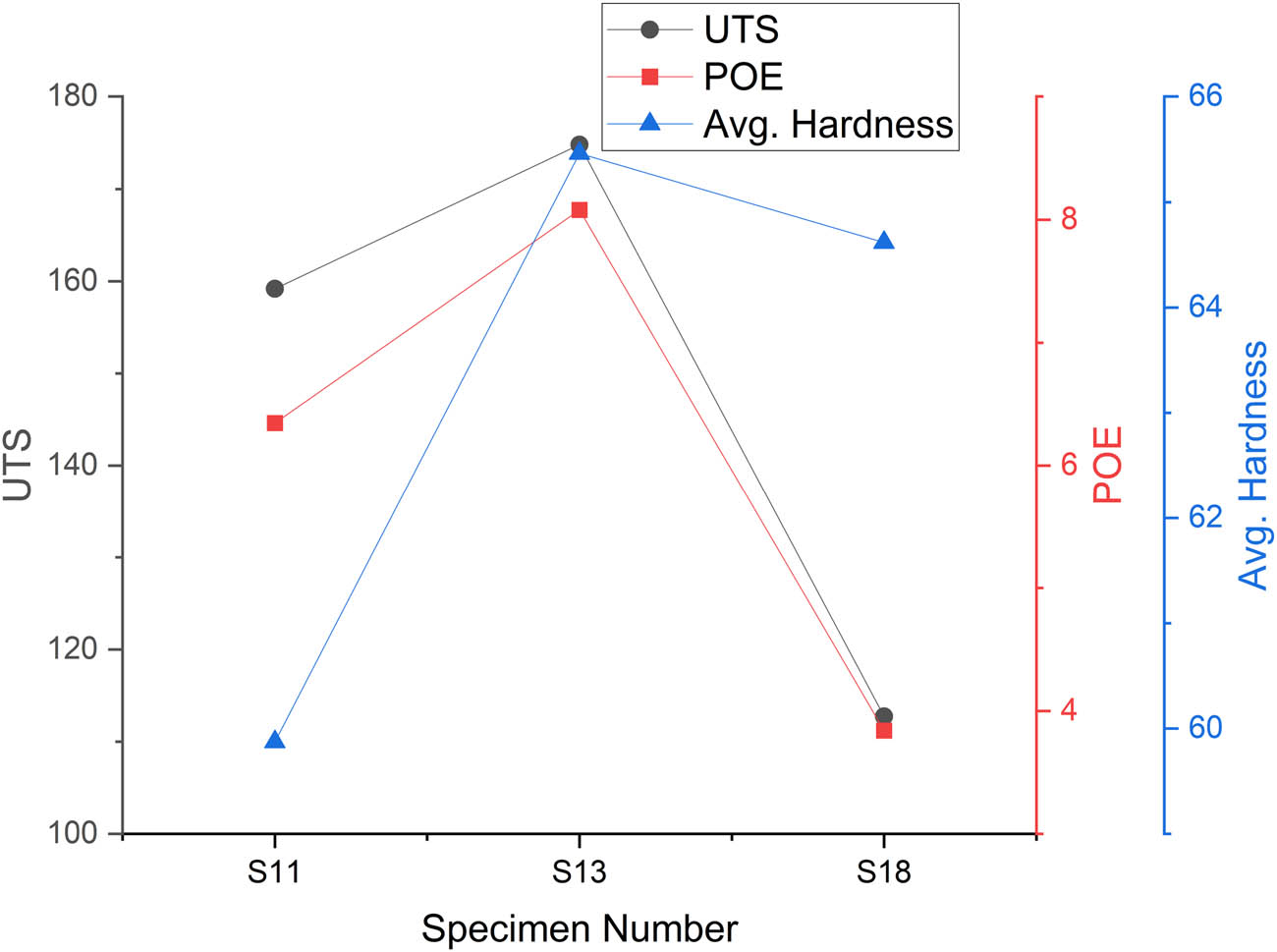
Graphical representation of mechanical properties at 1.2 mm hole diameter.
Graphical representation of mechanical properties at 1.6 mm hole diameter.
3.3.1 Effect of hole diameter 0.8 mm
At a hole diameter of 0.8 mm, the UTS values were consistently high, peaking at 205.26 MPa, indicating minimal structural degradation. The UTS of sample S15 is higher by 3.2 and 0.8% as compared to S10 and S17 samples, respectively. The percent of elongation exhibited a moderate value of 6.57%, and for the S15 sample, it is greater by 29 and 69% than S10 and S17 samples, respectively, ensuring a balanced set of mechanical properties.
Additionally, the hardness values were relatively low, with a minimum of 56.09, suggesting proper material consolidation. These findings suggest that a smaller hole diameter of 0.8 mm helps reduce the extent of material damage and minimize stress concentration during the hole processing operation.
3.3.2 Effect of hole diameter 1.2 mm
As the hole diameter was increased to 1.2 mm, the mechanical properties exhibited a noticeable decline. The UTS values were more moderate, with a significant decrease observed in specimen S18, which recorded a UTS of 112.73 MPa. This suggests that increasing the hole diameter begins to negatively impact the structural integrity of the material, likely due to the increased effect of material discontinuities. Similarly, the percent of elongation further decreased, with S18 exhibiting a value of 3.84%, indicating a loss in ductility.
The hardness values, however, remained moderate, with S18 recording a value of 64.62, potentially attributable to the increased stress concentration caused by the larger hole diameter.
3.3.3 Effect of hole diameter 1.6 mm
When the hole diameter was further increased to 1.6 mm, the mechanical properties exhibited a more pronounced deterioration. The UTS values were substantially reduced, with specimen S16 recording a UTS of 145.62 MPa, indicating a weaker material integrity. Additionally, the percent of elongation reached the lowest level observed at 3.45%, suggesting an embrittlement of the material.
Furthermore, the hardness values were the highest across all specimens, with S16 exhibiting a hardness of 86.83 HV, which can be attributed to strain hardening effects. The increased hole diameter of 1.6 mm appears to have introduced more discontinuities in the material, leading to a significant decline in ductility and an increase in localized strain hardening.
The findings indicate that a smaller hole diameter of 0.8 mm maintained higher UTS, while larger hole diameters led to increased hardness but reduced UTS. This suggests that increasing the hole diameter weakens the material structure by altering the stress distribution. Larger hole diameters create stress concentration zones, which can result in premature failure. Therefore, optimizing the hole diameter is crucial for preserving the structural integrity of the material. The sharp rise in hardness observed at a hole diameter of 1.6 mm implies that larger holes increase localized stress concentrations, making the material more susceptible to failure. Conversely, smaller hole diameters retained higher UTS and percent of elongation, whereas larger holes increased hardness but decreased ductility. These findings emphasize the importance of carefully selecting the optimal hole diameter to avoid material weakening.
3.4 Effect of tool pin profile
The tool pin profile influences the material flow and distribution of reinforcements, which in turn impact the mechanical characteristics. The findings for various tool pin profiles are presented in Tables 11–13, accompanied by their corresponding graphical representations in Figures 12–14.
Mechanical properties at TT pin profile
| Specimen number | UTS (MPa) | POE (%) | Avg. hardness (HV) |
|---|---|---|---|
| S10 | 198.73 | 8.64 | 67.55 |
| S14 | 170.33 | 5.80 | 64.02 |
| S18 | 112.73 | 3.84 | 64.62 |
Mechanical properties at SQ pin profile
| Specimen number | UTS (MPa) | POE (%) | Avg. hardness (HV) |
|---|---|---|---|
| S11 | 159.18 | 6.35 | 59.87 |
| S15 | 205.26 | 11.12 | 56.09 |
| S16 | 145.62 | 3.45 | 86.83 |
Mechanical properties at TH pin profile
| Specimen number | UTS (MPa) | POE (%) | Avg. hardness (HV) |
|---|---|---|---|
| S12 | 183.50 | 10.09 | 58.60 |
| S13 | 174.82 | 8.08 | 65.46 |
| S17 | 203.54 | 6.57 | 70.18 |
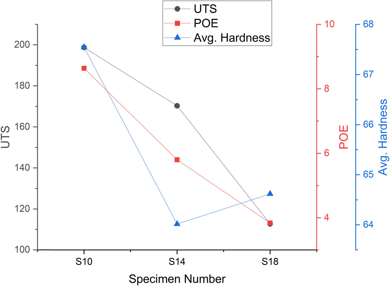
Graphical representation of Mechanical properties at TT pin profile.
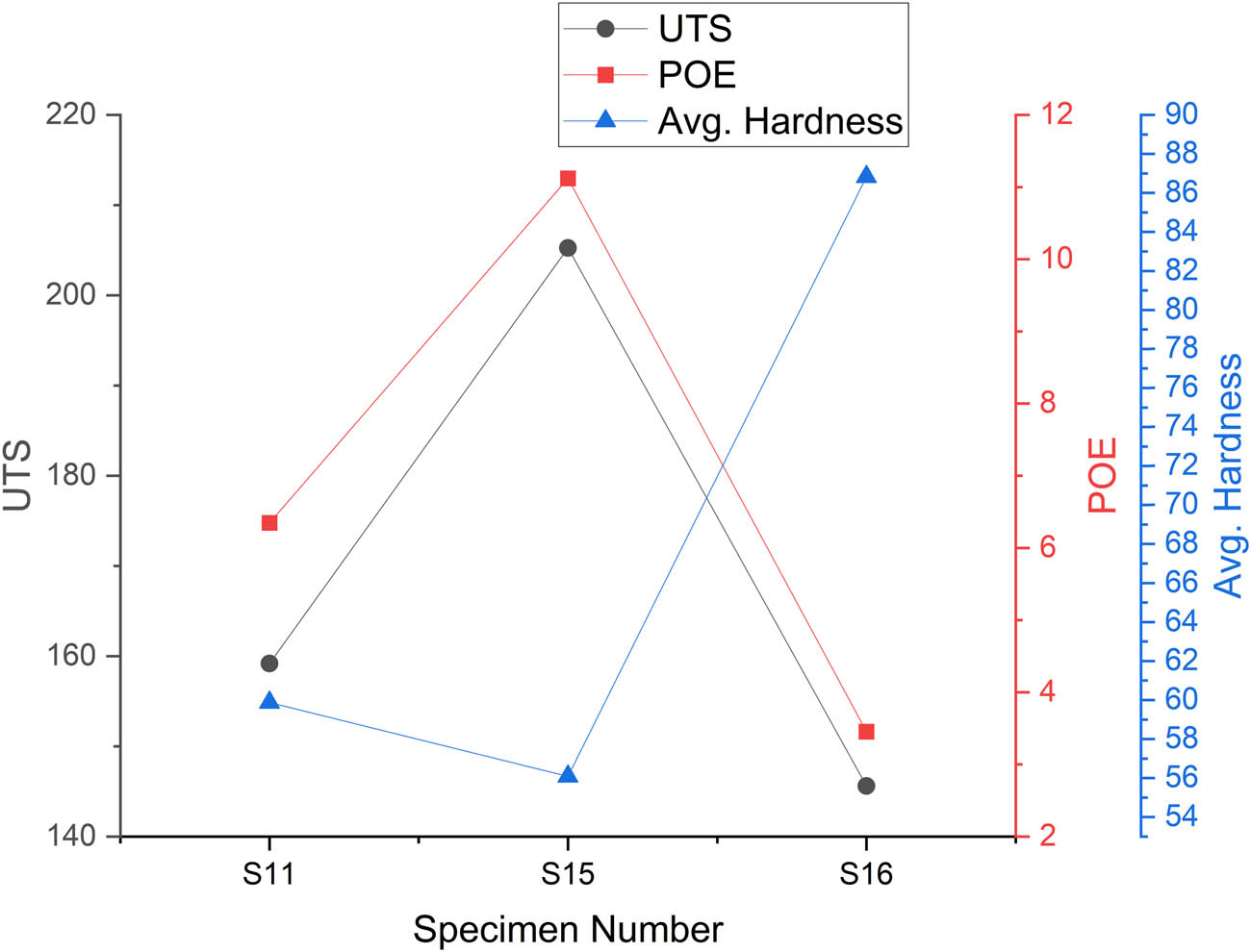
Graphical representation of mechanical properties at SQ pin profile.
Graphical representation of Mechanical properties at TH pin profile.
3.4.1 Effect of tool pin profile TT
Tapered threaded pin profile (TT) demonstrated a moderate range of UTS values, spanning from 198.73 to 112.73 MPa, which is there is a decrement by 43 and 14% observed in S14 and S18 as compared to the S10 sample, indicating a moderate degree of variation. The percent of elongation also varied significantly, though the elongation values remained within a moderate range. Notably, the hardness values were balanced, with a value of 64.62 HV, suggesting uniformity in the mechanical properties.
Overall, the TT profile facilitated a moderate UTS range and balanced hardness, which can be attributed to its ability to enable uniform heat generation and material mixing during the hole processing operation.
3.4.2 Effect of tool pin profile square headed (SQ)
The SQ tool pin profile exhibited a range of UTS values, with the highest recorded at 205.26 MPa but also a lower value of 145.62 MPa. This suggests that the SQ profile was capable of producing high UTS results in certain cases, but also demonstrated inconsistencies, indicating variability in the deformation process.
Additionally, the percent of elongation was higher, implying improved ductility. However, the hardness values were inconsistent across specimens, suggesting that the SQ profile led to uneven material behavior. Overall, the SQ tool pin profile provided the highest UTS observed, but lacked the consistency observed with other pin profiles.
3.4.3 Effect of tool pin profile TH
The TH pin profile demonstrated the most consistent mechanical performance. It achieved the highest UTS value of 203.54 MPa, indicating excellent structural integrity. Additionally, the moderate elongation of 6.57% ensured good ductility, while the balanced hardness of 70.18 HV confirmed optimized mechanical properties.
These findings suggest that the TH pin profile facilitated uniform heat generation and material flow, leading to a desirable combination of strength, ductility, and hardness. Thus, this pin profile can be considered a suitable choice for applications requiring balanced and consistent mechanical attributes.
The TH tool pin profile exhibited the most consistent and balanced mechanical characteristics. In contrast, the SQ tool displayed considerable variability, suggesting inconsistent heat generation and material flow during processing. The TT tool maintained moderate values, making it a suitable option for applications requiring uniform material properties. The tool pin profile influences material flow, heat generation, and grain refinement. A well-designed pin profile can enhance mechanical interlocking and weld quality. The TH pin facilitates more uniform and predictable heat input, leading to a desirable balance of mechanical properties.
3.5 Effect of process parameters on grain refinement and particle distribution
The microstructural characteristics of the Mg alloy composite reinforced with SiC particles were investigated under varying processing conditions using FSP. The key parameters evaluated included rotational speed, traverse speed, and tool pin profile. The resulting specimens displayed considerable differences in terms of grain refinement, particle distribution, and overall integrity of the processed zone.
3.5.1 Optical microscopy to analyze grain refinement and reinforcement particle distribution
The optical microscopy images provide insights into the grain refinement and particle distribution across different specimens processed using FSP. Figure 15(a)–(i) represents the optical microscopy images for the L9 specimen with various process parameter variations. Specimens processed at lower rotational speeds (545 RPM) with a TT tool, for sample S10, exhibit fine and uniform grain structures due to moderate heat input and efficient plastic deformation. The SiC reinforcement is well-dispersed for sample S10, contributing to enhanced mechanical properties. In contrast, specimens like S12, processed at higher feed rates (50 mm/min) and with a threaded (TH) tool, display coarser grain structures. The limited stirring effect results in uneven SiC distribution, leading to localized clustering and reduced strengthening effects.
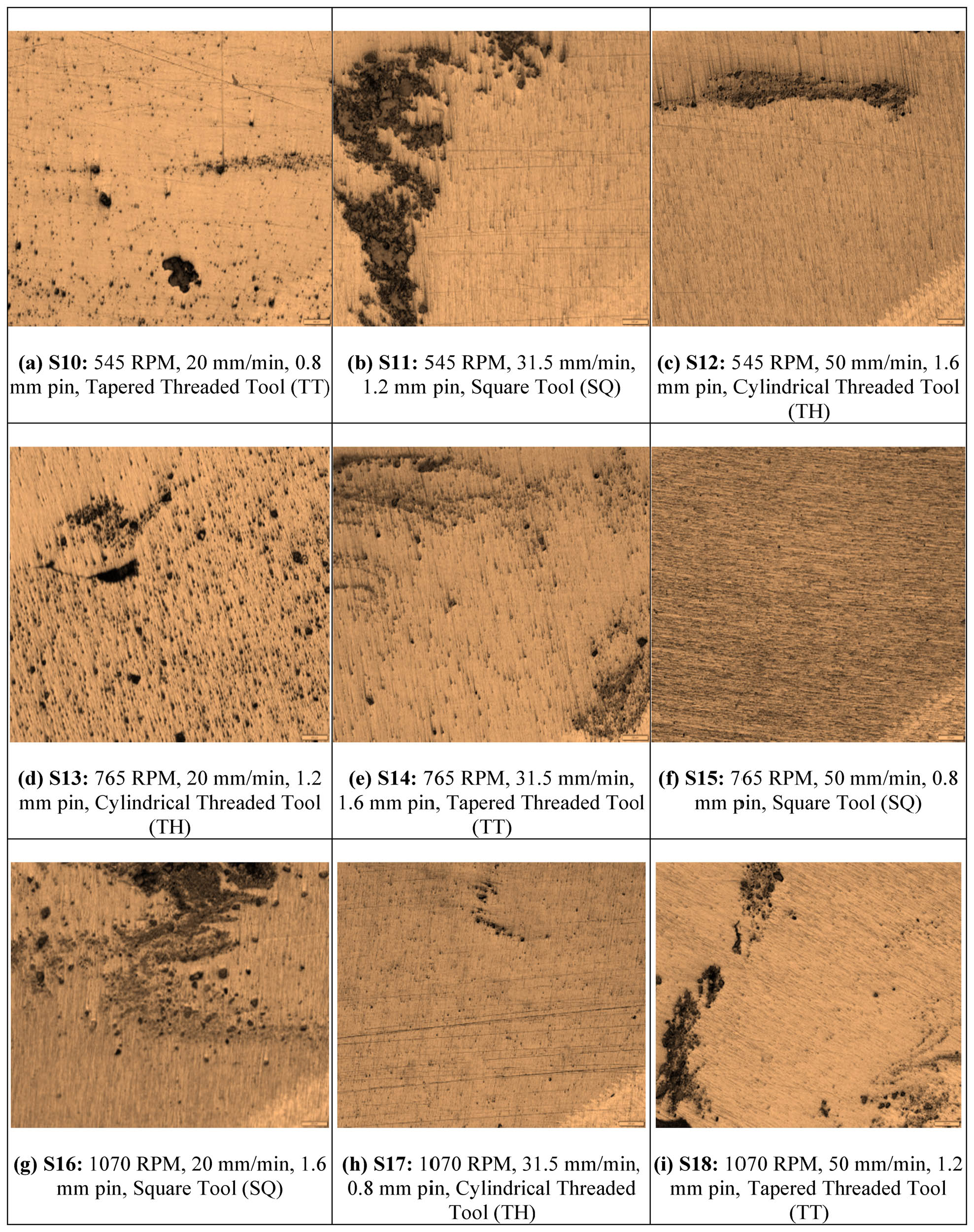
(a)–(i) Optical microscopy images for L9 specimen with various process parameter variations: (a) S10: 545 RPM, 20 mm/min, 0.8 mm pin, TT Tool. (b) S11: 545 RPM, 31.5 mm/min, 1.2 mm pin, SQ. (c) S12: 545 RPM, 50 mm/min, 1.6 mm pin, TH. (d) S13: 765 RPM, 20 mm/min, 1.2 mm pin, TH. (e) S14: 765 RPM, 31.5 mm/min, 1.6 mm pin, TT. (f) S15: 765 RPM, 50 mm/min, 0.8 mm pin, SQ. (g) S16: 1,070 RPM, 20 mm/min, 1.6 mm pin, SQ. (h) S17: 1,070 RPM, 31.5 mm/min, 0.8 mm pin, TH. (i) S18: 1,070 RPM, 50 mm/min, 1.2 mm pin, TT.
At intermediate rotational speeds (765 RPM), specimens like S13 and S14 show well-refined grain structures, with dynamic recrystallization enhancing grain boundary formation. The TT tool in S14 facilitates better mixing, resulting in improved particle dispersion. However, S15, processed at 50 mm/min with a SQ tool, exhibits a combination of fine and coarse grains, indicating that high traverse speed limits heat input, affecting the uniformity of grain refinement.
At the highest rotational speed (1,070 RPM), the grain structures become more refined in specimens like S16, which employs a square tool and a low feed rate (20 mm/min). The higher tool rotation enhances plastic flow, leading to fine grain refinement and a homogeneous microstructure. However, S18, processed at 50 mm/min with a TT tool, shows coarse grains and uneven SiC dispersion. The excessive traverse speed reduces stirring efficiency, preventing uniform grain refinement. The optical microscopy results confirm that optimal process parameters, particularly moderate rotational speeds (765 RPM) and feed rates (31.5 mm/min), lead to refined grains and uniform reinforcement dispersion, which directly impact mechanical properties.
3.5.2 SEM to analyze grain refinement and reinforcement particle distribution
The SEM images validate or confirms the findings obtained from optical microscopy by providing a detailed view of grain boundaries, reinforcement distribution, and defect formation. Specimens with optimized processing conditions, such as S10 and S16, exhibit a well-dispersed SiC phase with minimal clustering. The TT tool in S10 promotes uniform particle distribution, which enhances interfacial bonding between the reinforcement and the Mg matrix. This uniform dispersion contributes to the improved hardness and UTS observed in mechanical tests. Similarly, S16, processed at 1,070 RPM and 20 mm/min, exhibits strong interfacial bonding and homogeneous particle distribution, leading to the highest recorded hardness among all specimens. In contrast, SEM images of specimens processed at high feed rates, such as S12 and S18, reveal significant particle clustering and agglomeration. The inadequate stirring effect at higher traverse speeds limits the uniform distribution of SiC particles, resulting in stress concentration points that reduce mechanical performance. Specimens like S17 also show non-uniform particle dispersion with some reinforcement segregation at grain boundaries, which affects localized stress distribution and may contribute to reduced elongation properties. At intermediate speeds, specimens such as S14 and S15 show excellent dispersion with minimal porosity, confirming that a balanced combination of rotational and traverse speeds improves reinforcement distribution. The SEM analysis highlights the importance of processing parameters in achieving optimal microstructural characteristics. Moderate feed rates and moderate rotational speeds ensure effective material flow, preventing defects such as porosity and particle agglomeration, ultimately improving the composite’s mechanical performance (Figure 16).
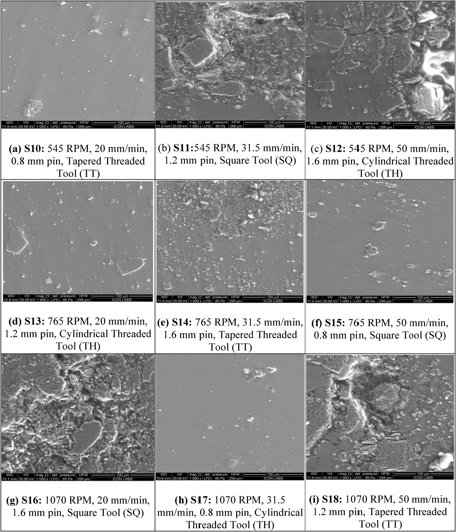
(a)–(i) SEM images for L9 specimen with various process parameter variations. (a) S10: 545 RPM, 20 mm/min, 0.8 mm pin, TT Tool. (b) S11:545 RPM, 31.5 mm/min, 1.2 mm pin, SQ. (c) S12: 545 RPM, 50 mm/min, 1.6 mm pin, TH. (d) S13: 765 RPM, 20 mm/min, 1.2 mm pin, TH. (e) S14: 765 RPM, 31.5 mm/min, 1.6 mm pin, TT Tool. (f) S15: 765 RPM, 50 mm/min, 0.8 mm pin, SQ. (g) S16: 1,070 RPM, 20 mm/min, 1.6 mm pin, SQ. (h) S17: 1,070 RPM, 31.5 mm/min, 0.8 mm pin, TH. (i) S18: 1,070 RPM, 50 mm/min, 1.2 mm pin, TT.
4 Conclusions
The present work investigated a comprehensive investigation of the effects of FSP on AZ31B Mg alloy reinforced with SiC particles, focusing on mechanical enhancement and microstructural refinement. The L9 orthogonal array approach provided the best combination of process parameters and valuable insights into the impact of tool geometry, rotational speed, traverse speed, and hole diameter on material performance. The optimal combination of a 765 RPM rotational speed, a 31.5 mm/min traverse speed, a 0.8 mm hole diameter, and a TH tool produced the best balance of tensile strength, hardness, and microstructural uniformity.
SEM and optical microscopy confirmed that homogeneous SiC particle dispersion resulted in significant grain refinement, which enhanced the mechanical properties and minimized defects. This study underscores the potential of FSP as a key technology for developing high-performance magnesium-based composites. This study successfully fabricated and characterized AZ31B-SiC surface composites using FSP with the hole method. The optimization of process parameters, specifically a rotational speed of 765 RPM, a traverse speed of 31.5 mm/min, and a hole diameter of 0.8 mm, yielded enhanced mechanical properties. This parameter set facilitated an effective equilibrium between tensile strength and ductility. Tool geometry significantly influences the material characteristics: TH tools provide a homogeneous particle distribution and superior grain refinement, whereas SQ tools increase tensile strength but compromise mechanical consistency. TT tools offer a compromise between hardness and strength. A traverse speed of 31.5 mm/min proved optimal for ensuring uniform heat distribution and effective dispersion of SiC particles. Elevated traverse speeds resulted in non-uniform material flow, thereby diminishing composite integrity. Furthermore, a reduced hole diameter enhanced both load transfer efficiency and wear resistance, rendering the composite more appropriate for demanding applications. Microstructural analysis via SEM and optical microscopy revealed considerable grain refinement and consistent dispersion of SiC particles, thereby augmenting hardness and tensile strength. Conversely, excessive rotational speeds induced grain coarsening, diminishing mechanical strength and ductility. Reduced hole diameters, however, improved the composite’s hardness and mechanical stability.
Acknowledgments
The authors would like to express sincere gratitude to Mechanical Department Research centre, Savitribai Phule Pune University, Pune.
-
Funding information: Authors state no funding involved.
-
Author contributions: All authors have accepted responsibility for the entire content of this manuscript and consented to its submission to the journal, reviewed all the results and approved the final version of the manuscript. Ravindra Parkhe: writing draft, date analysis, editing. Kanif Markad, Kishan Fuse, Badheka Vishvesh: conceptualization, writing, revision.
-
Conflict of interest: Authors state no conflict of interest.
-
Data availability statement: All data that support the findings of this study are included within the article (and any supplementary files).
References
[1] Tingjian Z, Lixia Z, Juan L. Ultrasonic vibration-assisted tensile mechanical behavior of magnesium alloy plate and constitutive mold. Chin J Plast Eng. 2020;27(12):170–6.Suche in Google Scholar
[2] Tan J, Ramakrishna S. Applications of magnesium and its alloys: A review. Appl Sci. Jul. 2021;11(15):6861. 10.3390/app11156861.Suche in Google Scholar
[3] Sampath B, Haribalaji V. Influences of welding parameters on friction stir welding of aluminum and magnesium: A review. In Materials research proceedings. Vol. 19, Oct. 2021. p. 222–30. 10.21741/9781644901618-28.Suche in Google Scholar
[4] Tesař K, Somekawa H, Singh A. Development of texture and grain size during extrusion of ZA63 alloy containing stable quaSiCrystalline i-phase and its effect on tensile and compression strength. J Alloy Compd. Dec. 2020;849:156340. 10.1016/j.jallcom.2020.156340.Suche in Google Scholar
[5] Chen J, Tan L, Yu X, Etim IP, Ibrahim M, Yang K. Mechanical properties of magnesium alloys for medical application: A review. J Mech Behav Biomed Mater. Nov. 2018;87:68–79. 10.1016/j.jmbbm.2018.07.022.Suche in Google Scholar PubMed
[6] Mineral commodity summaries 2020; 2020. 10.3133/mcs2020.Suche in Google Scholar
[7] Jasinski MP. Research design. In Social trust, anarchy, and international conflict. New York: Palgrave Macmillan US; 2011. p. 91–107. 10.1057/9780230118683_7.Suche in Google Scholar
[8] Parikh VK, Badgujar AD, Ghetiya ND. Joining of metal matrix composites using friction stir welding: A review. Mater Manuf Process. Jan. 2019;34(2):123–46. 10.1080/10426914.2018.1532094.Suche in Google Scholar
[9] Vijayakumar P, Pazhanivel K, Ramadoss N, Ganeshkumar A, Muruganantham K, Arivanandhan M. Synthesis and characterization of AZ91D/SiC/BN hybrid magnesium metal matrix composites. Silicon. Nov. 2022;14(16):10861–71. 10.1007/s12633-022-01823-3.Suche in Google Scholar
[10] Ali K, Mohanavel V, Vendan SA, Ravichandran M, Yadav A, Gucwa M, et al. Mechanical and microstructural characterization of friction stir welded SiC and B4C reinforced aluminium alloy AA6061 metal matrix composites. Materials. Jun. 2021;14(11):3110. 10.3390/ma14113110.Suche in Google Scholar PubMed PubMed Central
[11] Samal P, Vundavilli PR, Meher A, Mahapatra MM. Recent progress in aluminum metal matrix composites: A review on processing, mechanical and wear properties. J Manuf Process. Nov. 2020;59:131–52. 10.1016/j.jmapro.2020.09.010.Suche in Google Scholar
[12] Zhang C, Li Z, Zhang J, Tang H, Wang H. Additive manufacturing of magnesium matrix composites: Comprehensive review of recent progress and research perspectives. J Magnes Alloy. Feb. 2023;11(2):425–61. 10.1016/j.jma.2023.02.005.Suche in Google Scholar
[13] Jhamb S, Matai J, Marwaha J, Goyal A, Pandey A. A comprehensive analysis on magnesium-based alloys and metal matrix composites for their in-vitro biocompatibility. Adv Mater Process Technol. Jul. 2023;9(3):1249–82. 10.1080/2374068X.2022.2113521.Suche in Google Scholar
[14] Long J, Zhang LJ, Zhang LL, Wang X, Zhang GF, Zhang JX, et al. Effects of minor Zr addition on the microstructure and mechanical properties of laser welded joint of Al/SiCp metal-matrix composite. J Manuf Process. Jan. 2020;49:373–84. 10.1016/j.jmapro.2019.12.004.Suche in Google Scholar
[15] Selvaraj SK, Srinivasan K, Chadha U, Mishra R, Arpit K, Apurb K, et al. Contemporary progresses in ultrasonic welding of aluminum metal matrix composites. Front Mater. Apr. 2021;8:1–13. 10.3389/fmats.2021.647112.Suche in Google Scholar
[16] Ma L, Zhou C, Wen Q, Li M, Zhong H, Ji S. Ultrasonic-promoted rapid transient liquid phase bonding of high volume fraction SiC particle reinforced aluminum-based metal matrix composite in low temperature. Ultrasonics. Aug. 2020;106:106159. 10.1016/j.ultras.2020.106159.Suche in Google Scholar PubMed
[17] Wang C, Wang B, Xue P, Ni D, Xiao B, Hou X, et al. Effect of tool offsetting on friction stir welding of dissimilar aluminium matrix composite and aluminium alloy. Sci Technol Weld Join. Oct. 2022;27(7):586–93. 10.1080/13621718.2022.2091342.Suche in Google Scholar
[18] Palanikumar K, Natarajan E, Suresh S, Mohan DG, Prakash C, Kaur K. Prospects of friction stir processed Mg alloys and composites-Reviews and suggestions. J Mater Res Technol. Jul. 2024;31:971–97. 10.1016/j.jmrt.2024.06.087.Suche in Google Scholar
[19] Mishra SC. Analysis of experimental results of plasma spray coatings using statistical techniques. Advanced plasma spray applications. Croatia: InTech; 2012 Mar. p. 83–96.10.5772/33032Suche in Google Scholar
[20] Rotella G, Saffioti MR, Sanguedolce M, Umbrello D, Filice L. Tribocorrosion behavior of Ti6Al4V machined and burnished components for biomedical application. Key Eng Mater. Jul. 2022;926:1629–35. 10.4028/p-y55l72.Suche in Google Scholar
[21] Thomas WM, Nicholas ED, Needham JC, Murch MG, Temple Smith P, Dawes CJ. Friction stir butt welding GB Patent 9125978.8 [P]1991−12−06.Suche in Google Scholar
[22] del Valle JA, Rey P, Gesto D, Verdera D, Jiménez JA, Ruano OA. Mechanical properties of ultra-fine grained AZ91 magnesium alloy processed by friction stir processing. Mater Sci Eng: A. Mar 2015;628:198–206. 10.1016/j.msea.2015.01.030.Suche in Google Scholar
[23] Zang Q, Chen H, Lan F, Zhang J, Jin Y. Effect of friction stir processing on microstructure and damping capacity of AZ31 alloy. J Cent South Univ. May 2017;24(5):1034–9. 10.1007/s11771-017-3506-9.Suche in Google Scholar
[24] Raja A, Biswas P, Pancholi V. Effect of layered microstructure on the superplasticity of friction stir processed AZ91 magnesium alloy. Mater Sci Eng: A. May 2018;725:492–502. 10.1016/j.msea.2018.04.028.Suche in Google Scholar
[25] MD FK, Panigrahi SK. Achieving excellent superplasticity in an ultrafine-grained QE22 alloy at both high strain rate and low-temperature regimes. J Alloy Compd. May 2018;747:71–82. 10.1016/j.jallcom.2018.02.294.Suche in Google Scholar
[26] Singh Sidhu H, Singh B, Kumar P. To study the corrosion behavior of friction stir processed magnesium alloy AZ91. Mater Today Proc. 2021;44:4633–9. 10.1016/j.matpr.2020.10.920.Suche in Google Scholar
[27] Shang Q, Ni DR, Xue P, Xiao BL, Wang KS, Ma ZY. An approach to enhancement of Mg alloy joint performance by additional pass of friction stir processing. J Mater Process Technol. Feb. 2019;264:336–45. 10.1016/j.jmatprotec.2018.09.021.Suche in Google Scholar
[28] Patel V, Li W, Liu X, Wen Q, Su Y, Shen J, et al. Tailoring grain refinement through thickness in magnesium alloy via stationary shoulder friction stir processing and copper backing plate. Mater Sci Eng: A. May 2020;784:139322. 10.1016/j.msea.2020.139322.Suche in Google Scholar
[29] Vidal C, Ferreira PM, Inácio PL, Ferreira FB, Santiago D, Meneses P, et al. Particles’ distribution enhancing in aluminum-based composites produced by upward friction stir processing. Int J Adv Manuf Technol. Jul. 2023;127(5–6):2745–57. 10.1007/s00170-023-11664-y.Suche in Google Scholar
[30] Thangarasu A, Boovendra Varma S, Sudharsan S. Microstructure and wear behaviour of aluminium surface composites fabricated using friction stir processing. IOP Conf Ser Mater Sci Eng. Sep. 2020;932(1):012132. 10.1088/1757-899X/932/1/012132.Suche in Google Scholar
[31] Gao Y, Hao K, Xu L, Han Y, Zhao L, Ren W, et al. CNTs distribution and ductility improvement mechanisms in oscillating laser-arc hybrid welding of AZ31B magnesium alloy. Compos Part A Appl Sci Manuf. Jan. 2023;164:107280. 10.1016/j.compositesa.2022.107280.Suche in Google Scholar
[32] Singla S, Kang AS, Sagar P, Handa A. Recent advances in magnesium-based metal matrix surface composites developed via friction stir processing route—An overview. Metallogr Microstruct Anal. Dec. 2023;12(6):1068–8. 10.1007/s13632-023-01030-5.Suche in Google Scholar
[33] Omran SH, Al-Masoudy MM, Hassoon OH, Fayad MA. Optimization of mechanical wear resistance for recycled (Al-Mg-Si) reinforced SiC composite material using PM method. Curved Layer Struct. Jan. 2022;9(1):295–303. 10.1515/cls-2022-0023.Suche in Google Scholar
[34] AL-Mushehdany A, Yahya MM, Ibrahim EK, Alalkawi HJM. Nano reinforcement technique as a tool for enhancement the mechanical and fatigue properties. Curved Layer Struct. Jan. 2022;9(1):345–51. 10.1515/cls-2022-0026.Suche in Google Scholar
[35] Sharma DK, Patel V, Badheka V, Mehta K, Upadhyay G. Different reinforcement strategies of hybrid surface composite AA6061/(B4C + MoS2) produced by friction stir processing. Mater Sci Eng Technol. 2020;51(11):1493–506. org/10.1002/mawe.202000130.Suche in Google Scholar
[36] Test methods for tension testing of metallic materials, May 01, 2022, ASTM International, West Conshohocken, PA. 10.1520/E0008_E0008M-22.Suche in Google Scholar
[37] Test methods for vickers hardness and knoop hardness of metallic materials, Apr. 01, 2017, ASTM International, West Conshohocken, PA. 10.1520/E0092-17.Suche in Google Scholar
© 2025 the author(s), published by De Gruyter
This work is licensed under the Creative Commons Attribution 4.0 International License.
Artikel in diesem Heft
- Research Articles
- Layerwise generalized formulation solved via a boundary discontinuous method for multilayered structures. Part 1: Plates
- Thermoelastic interactions in functionally graded materials without energy dissipation
- Layerwise generalized formulation solved via boundary discontinuous method for multilayered structures. Part 2: Shells
- Visual scripting approach for structural safety assessment of masonry walls
- Nonlinear analysis of generalized thermoelastic interaction in unbounded thermoelastic media
- Study of heat transfer through functionally graded material fins using analytical and numerical investigations
- Analysis of magneto-aerothermal load effects on variable nonlocal dynamics of functionally graded nanobeams using Bernstein polynomials
- Effective thickness of gallium arsenide on the transverse electric and transverse magnetic modes
- Investigating the behavior of above-ground concrete tanks under the blast load regarding the fluid-structure interaction
- Numerical study on the effect of V-notch on the penetration of grounding incidents in stiffened plates
- Thermo-elastic analysis of curved beam made of functionally graded material with variable parameters
- Effect of curved geometrical aspects of Savonius rotor on turbine performance using factorial design analysis
- A mechanical and microstructural investigation of friction stir processed AZ31B Mg alloy-SiC composites
- Mechanical design of engineered-curved patrol boat hull based on the geometric parameters and hydrodynamic criteria
- Review Article
- Technological developments of amphibious aircraft designs: Research milestone and current achievement
- Special Issue: TS-IMSM 2024
- Influence of propeller shaft angles on the speed performance of composite fishing boats
- Design optimization of Bakelite support for LNG ISO tank 40 ft using finite element analysis