Design optimization of Bakelite support for LNG ISO tank 40 ft using finite element analysis
-
Tuswan Tuswan
 ,
Rafif Naufal Taufiq
,
Rafif Naufal Taufiq

Abstract
Design optimization of a liquefied natural gas (LNG) ISO tank is essential to ensure structural integrity while minimizing weight. This approach enables the identification of efficient material distributions under critical loading conditions, enhancing safety, compliance with ISO 1496 standards, and overall transport efficiency without compromising strength. This study proposes a topology optimization for the Bakelite support structure of a 40 ft LNG ISO tank that balances structural strength and weight efficiency. The optimization process incorporates two main strategies: strain energy minimization and mass retain, defined as the objective function and constrained within a 90–50% mass retain range. To ensure structural integrity and regulatory compliance, the resulting designs are evaluated under the ISO 1496 standard loading scenarios, including lifting, stacking, and racking. Initial mesh convergence study of the proposed finite element analysis model shows optimum mesh selection with optimum computational time. The topology optimization results with mass retain ranging from 90 to 50% in all loading scenarios achieved a substantial weight reduction in the Bakelite support, between 4.81 and 81.41%, by eliminating the Bakelite application in the middle support of the pressure vessel. The optimized Bakelite support slightly increases stress and deformation in both the pressure vessel and the Bakelite support, remaining within the standard criteria limits. The proposed optimization is promising in maintaining structural strength compliance with ISO 1496 standards.
1 Introduction
Liquefied natural gas (LNG) is purified natural gas that has undergone the removal of heavy hydrocarbon elements [1]. LNG holds a considerable market share in the global market as an alternative energy source to diesel or heavy fuel oil (HFO) [2]. LNG can serve as a fuel alternative, especially in the maritime sector. LNG as a fuel can reduce fuel costs due to its lower calorific value compared to diesel or HFO. For its operational requirements, an Ignition-Compression engine running at the same power level will use less LNG [3]. As an alternative energy source, Indonesia possesses more extensive natural gas reserves than crude oil reserves [4], with Indonesia holding 1.5% of the world’s natural gas reserves [5].
As a low heating value energy source, LNG prices are estimated to reach 60% of HFO prices. However, to accommodate the needs of high-speed diesel fuel tanks, LNG usage requires tanks that are 2.5 times larger due to their lower density and the need for additional layers to maintain temperature [6]. Using gas as a ship fuel also significantly reduces carbon dioxide emissions, with approximately 85–90% reduction in nitrogen oxide emissions and almost 100% reduction in sulfur oxide emissions [6]. It aligns with regulations issued by MARPOL Annex VI, IMO regarding emission limits, ensuring that LNG continues to meet standards up to Tier III [7]. Furthermore, the use of gas as fuel aligns with government policies outlined in Government Regulation No. 55 Year 2009, allocating 25% of total natural gas production for domestic use [8].
In distributing LNG in Indonesia, attention must be paid to an effective LNG distribution system. LNG distribution methods to consumers can be divided into pipeline delivery, tanker trucks, and tanker containers [9]. Most offshore or LNG terminal facilities receive LNG transported by ships. Floating storage and regasification units are a common component of offshore facilities because LNG is distributed to end-users at extremely low temperatures, around −165°C, and pressures of 13 bar, necessitating pressure vessels such as ISO tanks for its distribution [10,11]. Therefore, under the National Priority Program (PRN) for the maritime sector from 2020 to 2024, the National Development Planning Agency collaborated with the National Research and Innovation Agency (BRIN) to prioritize the development of mini LNG carrier, which includes the design of mini LNG carrier and the ISO tank design.
Transporting products such as gasses, liquids, or dangerous chemicals is carried out in ISO tanks, with valves installed for further security [12]. ISO tanks are commonly used as containers for distributing natural gas to areas not connected by gas pipelines. The components of an ISO tank are an outside carbon steel tank to maintain vacuum and regulate cargo temperature, and an inside stainless steel tank to hold liquids up to −196°C, the ASME Sec. VIII Div. 1 standards are used for designing ISO tanks [13]. The main components of LNG ISO tanks include the inner shell, outer shell, baffle, Bakelite support, ring stiffener, and frame structure. The inner and outer pressure vessel tank structures are connected by Bakelite support [14]. Muttaqie et al. [15] analyzed ISO 20 ft LNG tanks following ASME procedures in their design. Additionally, ISO 1496 standards were used to evaluate operational loads as the basis for finite element analysis (FEA) simulation.
ISO tank design must consider several factors, such as safety and design weight [15]. Marpaung et al. [16] tested ISO 40 ft LNG tanks according to ISO 1496 standards, including lifting, stacking, and racking tests. The results indicated that the bottom-end frame structure received maximum pressure and thus required refinement to increase operational safety. The recent study by Purnamasari et al. [17] analyzed the structural strength of ISO 40 ft LNG tank frames using ISO 1496 standards, identifying stacking and racking as critical operational loading scenarios. Fatigue research on ISO 40 ft LNG tank structures has been conducted under low and high-cycle conditions, but did not consider multi-stacking scenarios in their loads, as performed by Lee et al. [12]. Lakshmikanth Chowdary [18] researched the shapes of pressure vessel heads (inner and outer shells), including flat heads, hemispherical heads, conical heads, ellipsoidal heads, and torispherical heads. Wang and Qian [19] investigated the influence of fluid inertia forces on stress distribution and tank safety factors under various loading conditions using finite element methods. Utilizing FEA software, container tank stress analysis and strength evaluations were conducted, demonstrating the reliability and safety of container structures [20]. Similarly, Zhaochun et al. [21] described stress distribution and displacement of LNG container tanks influenced by inertia forces, ensuring that the structures used meet the required strength criteria.
The optimization of the Bakelite support in an LNG ISO tank is crucial for enhancing structural efficiency while minimizing unnecessary material usage. As the Bakelite support plays a key role in securing and distributing loads within the tank framework, optimizing its geometry can lead to significant weight savings, which is particularly important in transportation applications where weight directly impacts cost and fuel efficiency. Given the increasing demand for lightweight, high-performance cryogenic transport systems, such optimization contributes to improved structural performance. One method to achieve an optimal design while considering weight and strength is topology optimization. Topology optimization has been widely used to produce lighter designs without compromising strength. Qiu et al. [22] discussed topology optimization of cargo space in tanker ships considering hull weight using a finite element method approach. Insano and Rochardjo [23] researched topology optimization of train nose frame structures using a finite element approach, considering safety and structural strength factors. Research on boom excavators with topology optimization resulted in more optimal designs that were lighter than the initial design while still being deemed safe [24]. Huda et al. [25] conducted a study on topology optimization of fall block deck cranes using finite element methods, successfully reducing the initial design weight while considering safe stress values. A recent survey by Tuswan et al. [26], focusing on enhancing the structural frame design of tanks, was conducted on ISO 40 ft LNG tanks, demonstrating that optimization scenarios could result in weight reductions of 18.4–37.3% while maintaining stress levels below criteria thresholds.
Based on the studies mentioned above, topology optimization has emerged as a powerful design methodology in various engineering fields, enabling the development of structurally efficient, lightweight, and cost-effective components. Despite its growing application, topology optimization is yet to be explored in designing Bakelite support structures in pressure vessels for LNG ISO tanks, a critical yet overlooked component in cryogenic containment systems. These supports play a vital role in maintaining the structural integrity of the inner tank during handling, transport, and operational loading because the geometry and mass contribute to the overall weight and mechanical stability of the tank system. Therefore, the absence of optimization in this area represents a significant gap in current research and design practices.
This research aims to propose a lighter Bakelite support design for ISO 40 ft LNG tanks using topology optimization methods with FEA software. Mass retain is assumed to be 50–90%, which is proposed to optimize Bakelite support under operational loading conditions according to ISO 1496. Convergence analysis is employed initially to attain mesh efficiency with optimal computational time. The optimized Bakelite support is evaluated by comparing the total weight savings of the LNG ISO tanks and their structural performance under operational loading conditions. This research can be utilized to minimize the production costs of pressure vessels, especially Bakelite support, by simplifying the design. Lighter and more efficient designs can benefit manufacturers and end-users by maintaining or enhancing structural performance while reducing material costs.
2 Materials and methods
In the materials and methods, several discussions are presented. Section 2.1 discusses the topology optimization framework used for Bakelite optimization of the LNG ISO tank. Optimization using the Eulerian theory is discussed. In Section 2.2, design specifications, including cross-section geometry of the pressure tank and design parameters of the pressure tank and Bakelite support, are calculated according to ASME Sec. VIII. The loading scenario and boundary condition setting for the topology optimization test according to ISO 1496 will be presented.
2.1 Topology optimization framework on LNG tank
Topology optimization is one of the optimization methods used to determine the optimal structural configuration by modifying the layout of its constituent components. By considering the received loads, topology optimization eliminates elements from the design by redistributing the load on the material to create the lowest mass of the layout. Elements with minimal critical loads will be eliminated, but those with high critical loads will be retained. The design of these elements will only leave parts with sufficiently high critical loads, resulting in a relatively lightweight layout [27]. Three steps represent the topology optimization method for the Bakelite support used in this work. The first step involves verifying that the design satisfies the requirements outlined in ASME Sec. VIII Div. 1 [13] and assessing the ISO 40 ft LNG tank’s performance under various loading scenarios using ISO 1496 [28] to ascertain the strength of the current design in every component.
The objective function, F, is determined in the general case of topology optimization problems. This function is subject to volume limitations, written as G 0 ≤ 0. Furthermore, G i ≤ 0 can describe various restrictions for i = 1, …, N. The density variable ρ(x), which might have a value of 0 (showing space) or 1 (representing the existence of solid material) at any position, describes the distribution of material within the design domain Ω. This optimization issue can be expressed mathematically as Eq. (1).
For example, the objective function can be considered the integral of the local function f(u(ρ), p) where the domain u satisfies linear or nonlinear equations. It can be used to discuss compliance optimization of the strain energy density.
Eq. (1) can be explained using two different methods: The Eulerian technique with a fixed mesh and the Lagrangian approach, also referred to as the boundary-following mesh. Imposing many constraints in this situation could result in issues with similar gaps. The density variable’s discrete character (0 or 1) makes it more challenging to identify the ideal answer. This problem is essential in Eulerian theory. To tackle this issue, realistic gradient-based optimization techniques are needed. As a result, this issue falls under the category of continuous topology optimization. The design of these algorithms aims to guarantee convergence in a reasonable number of iterations. The problem can be formulated using Eq. (2).
A field function that can be applied to solid materials is F 0 (u), a density interpolation function is g(ρ), and ρ is a design variable vector of length N. The link between density and material qualities is described by the component f(u, ρ) of Eq. (1), which can be expressed as f(u,ρ) = 0. This formula fulfills the equilibrium equation at every optimization step in the previously discussed methodologies. The key objective of topology optimization is to reduce the strain energy when the structural constraints are fulfilled. The strain energy obtained by giving density to each constituent unit through the design variable will be lessened by structural stiffness.
The main objective is to decrease strain energy when structural constraints are satisfied. By increasing the density of individual pieces through design modifications, strain energy can be reduced by improving structural stiffness. The formulation of strain energy (U) is given by Eq. (3).
Calculating the minimum strain energy needed for a specific load to maximize stiffness while considering volume restrictions is essential. This sets the minimal standard of compliance.
2.2 Design specification of LNG ISO tank 40 ft
In this section, the proposed flowchart of the optimization process of Bakelite design is discussed. The geometry and material selection of the pressure vessel according to the ASME standard are discussed in Section 2.2.1. Section 2.2.2 discusses the operating loading calculation used for topology optimization based on ISO 1496.
2.2.1 Design parameters
The optimization process starts with determining the area or design that must be optimized, as shown in Figure 1. At this point, the complete Bakelite support structure has been chosen as the design area. It is necessary to establish design answers in the optimization process. In this instance, strain energy and volume are design responses. The target function to be minimized is strain energy, with a maintained volume percentage ranging from 90 to 50%. After the lowest strain value is found, the optimization procedure ends. The optimal outcomes must be redesigned as the last phase. Redesigning is required to enhance the geometry and make the design more appropriate for production processes. The redesigned results are put to ISO 1496 loading conditions to find design flaws that can be fixed, and a better design is suggested. Figure 2 illustrates the external and internal structure of the LNG ISO tank 40 ft. This section discusses the process of material selection and the determination of the minimum thickness required for the pressure vessel tank. The minimum thickness of the pressure vessel, material selection, and allowable material limits are determined based on ASME Sec. II and VIII [29].
Topology optimization flowchart for LNG ISO tank.

Cross-section of the LNG ISO 40 ft pressure vessel tank.
The material used in the calculations is alloy steel SUS 304L manufactured by Surya Logam Universal Tbk, Tangerang, Indonesia, with specifications SA 240 Gr 304L-S 30403 according to ASME Sec. II [30]. This type of material is grade 304L stainless steel with low carbon content, known as UNS30403. To ensure compliance with ASME implementation for establishing the minimum thickness of pressure vessels and material selection to meet safety and functionality standards in LNG transportation operations, ASME Sec. II strictly limits the choice of material attributes. UG-27 ASME Sec. VIII Div. 1 describes the minimum thickness, while Figure 2 thoroughly breaks down the input parameters. Eq. (4) determines the minimal thickness of the pressure vessel.
where S is the maximum permitted stress for SUS 304L, R is the internal radius, and P is the internal design pressure. The proper butt joint efficiency, on the other hand, is represented by E (Table UW-12 ASME [13]). Furthermore, Eqs. (5) and (6), based on ASME Section VIII Division 1, UG-32, are used to calculate the torispherical heads at both ends of the pressure vessel cylinder.
Additionally, ASME Sec. VIII, Div. 1, UG-28 [12] uses the maximum allowed external pressure estimation for the associated cylinder shell design. R = the inner radius, and L = the inner crown radius. It is necessary to confirm that D0/t ≥ 10 before using this computation. After verification, the A value is determined using the fundamental values of L/D0 and D0/t by utilizing the reference graph for external loads in ASME Sec. II Part D Subpart 3 [29]. The B value corresponding to the 304L material specification is computed after acquiring the A value. Eq. (7) uses the B value to get the maximum value. Based on UG-33, the B value employed in Eq. (8), this procedure is directly proportional to calculating the convex surface from the maximum pressure on the cylinder head.
This calculation is related to UG-29 of ASME Sec. VIII, Div. 1 [13], aiming to determine the pressure on stiffener rings in the pressure vessel. This method is required for this section by assuming the original size and shape of the stiffener rings.
where t represents the estimated shell thickness from the previous phase, A S represents the cross-sectional area of the expected stiffener rings, and L S indicates the space between the stiffeners, the external pressure table in ASME Sec. II Part D [29] can calculate the same value as A using B.
Eq. (10) is used to obtain the stiffener ring’s necessary moment of inertia. Then, using the first set of assumptions given in Eq. (11), the stiffener ring’s real moment of inertia is verified. Table 1 shows the pressure vessel thickness calculated based on ASME Section VIII. The code also stipulates that the required moment of inertia must be equal to or greater than the actual moment of inertia.
Design parameters of LNG ISO tank according to ASME Sec. VIII [13]
| Design parameters | Value | Unit |
|---|---|---|
| Internal design pressure (P int) | 1 | MPa |
| External design pressure (P ext) | 0.8 | MPa |
| Inner tank parameter | ||
| Inner shell thickness (t) | 7.1 | mm |
| Inner head thickness (t) | 11.22 | mm |
| Diameter of inner tank (D) | 2,218 | mm |
| Cylindrical length of inner tank (L cyl) | 11,018 | mm |
| Inner crown radius (L) | 2,218 | mm |
| Inner knuckle corner radius (r) | 221.8 | mm |
| Outer tank parameter | ||
| Outer shell thickness (t) | 3.95 | mm |
| Outer head thickness (t) | 6.28 | mm |
| Diameter of outer tank (D) | 2,438 | mm |
| Cylindrical length of outer tank (L cyl) | 11,018 | mm |
| Outer crown radius (L) | 1950.4 | mm |
| Outer knuckle corner radius (r) | 243.8 | mm |
2.2.2 Loading scenario according to ISO 1496
Loading scenarios specified by ISO 1496 are used in FEA analysis to calculate strength and determine certification approval requirements. New or modified designs are required to undergo ISO 1496 loading testing [28]. The loading scenarios are computed based on the ISO 1496 standard presented in Table 2. The LNG ISO tank, which is 40 feet in height, is categorized as Class A in this table, with a stacking load of 942 kN at each leg mounting point. The lowest load produced is 8 tons (73 kN), assuming the LNG ISO tank 40 ft container’s gross weight is 35.42 tons, divided equally at each corner. As a result, ISO 1496 states that standards for high strength can be met at three levels (without considering a safety factor of 1.8). The LNG ISO tank 40 ft layout design is shown in Figure 3, and the cargo layout situations are explained in Table 2.
Systematic loading scenarios according to ISO 1496
| Load scenario | Load value | Load configuration | |
|---|---|---|---|
| Lifting test |
|
|
|
| 2R – T = 532.20 kN | |||
| Stacking test | F = 942 kN |
|
|
| 1.8R – T = 462.69 kN | |||
| 942 +
|
|||
| Racking test (transversal direction) | F = 150 kN |
|
|

Design of the LNG ISO tank 40 ft.
Based on ISO 1496 [28], there are three loading scenarios: lifting, stacking, and racking, as presented in Table 2. To determine the magnitude of loading for each scenario, it is necessary to calculate the weight of the model performed by the software by computing the total material weight and thickness in each section. From the total weight calculation with the software, the tare weight (T) is obtained, which is 16.60 tons, and the gross weight (R), which is 35.42 tons.
The lifting test determines how well the container can support lifting loads applied vertically from the four corner fittings. The lifting test assesses the container floor’s resistance to acceleration loads during lifting. The total weight of the container and the test load is 2R when the test load is evenly distributed across the floor. The container can be kept from experiencing strong acceleration or deceleration forces by raising its four upper corners. The lifting approval submission parameters are the gross weight (R) and the tare weight (T). The stacking test determines how well a container can support loads when stacked. According to ISO 1496, the container is loaded with a vertical load of 942 kN (384 tons) applied at each of the four corners. The LNG tank’s displacement load accounts for 189.2 kN (19.3 tons) of the total cargo. The ISO tank structure’s ability to sustain the stack load at sea is tested via stacking. The racking test determines how strong a container will be structurally when subjected to racking loads and transported by various means, including trains and ships. The ISO tank is loaded with 150 kN of cargo and left empty for this test. The racking test aims to determine whether the container can sustain the transverse racking forces that the movement of transportation modes generates on the end frame.
2.3 Numerical FE topology optimization method
This section outlines the FEA procedure for the topology optimization of the LNG ISO tank structure. Section 2.3.1 details the definition of the computational domain and the rationale behind the selection of materials. A discussion on the applied boundary conditions and contact interactions within the FEA framework follows this. The results of the mesh convergence study are presented in Section 2.3.3, while the optimization strategy for the Bakelite support structure is elaborated in Section 2.3.4.
2.3.1 Computational domain and material selection
The numerical simulation approach using FEA has been extensively utilized in various engineering design fields to investigate components’ structural and mechanical behavior [26]. Ansys software was selected as the FEA auxiliary software for modeling and simulation. The process comprises three stages: first, a 3D model of the LNG ISO tank is created using SolidWorks; second, the 3D model is discretized by defining geometry, material properties, loading scenarios, and constraints using Ansys software; and third, a nonlinear static analysis is employed to understand the physical impact of these parameters.
The inner and outer heads, Bakelite support, baffle, stiffener ring, inner and outer shell, and structural frame comprise the ISO tank geometry. The correct modeling of these components represents the precise dimensions of the ISO tank. The tank’s material properties are assumed to behave linearly elastically, leading to complete plasticity. According to this method, a material can exhibit plastic displacement without experiencing further stress after it reaches a particular point of elastic behavior. It suggests that the stress stays constant during the material’s plastic displacement. This method clarifies optimal circumstances like homogeneous stress distribution and isotropic material characteristics. Consequently, the perfect plasticity elastic material model is frequently employed in engineering because of its ease of use and capacity to offer conservative approximations of material behavior under certain circumstances. ASME Sec II is the basis for choosing the suitable material for the LNG ISO tank [25]. The LNG ISO tank’s complete material properties are shown in Table 3. In this instance, the tank’s inner shell, inner head, and baffle are made of SA240Gr304L-PV material. Simultaneously, the stiffener ring, outer shell, outer head, Bakelite support, and Bakelite cover are made of ASTM A516 carbon steel.
Material constants of the LNG ISO tank components
| Materials | Elasticity properties | Plasticity properties | |||
|---|---|---|---|---|---|
| Density | Young modulus | Poisson’s ratio | Yield strength | Plastic strain | |
| (ton/mm3) | (N/mm2) | – | (N/mm2) | – | |
| Steel frame [31] | 7.85 × 10⁻⁹ | 210,000 | 0.3 | 340 | 0 |
| SA240Gr304L-PV [30] | 7.85 × 10⁻⁹ | 193,000 | 0.3 | 175 | 0 |
| ISO corner casting [32] | 7.85 × 10⁻⁹ | 215,800 | 0.3 | 275 | 0 |
| Carbon steel ASTM A516 [33] | 7.85 × 10⁻⁹ | 200,000 | 0.3 | 248 | 0 |
| Bakelite [34] | 1.28 × 10⁻⁹ | 8,300 | 0.29 | 55 | 0 |
2.3.2 Boundary condition and contact interaction parameters
In the contact parameter, kinematic coupling is applied to the top and bottom regions with motion constraints to reduce computational time. The approach utilizes constraints to obtain the rigid body motion from a specific reference point within a set of nodes. Nodes that are effectively connected are locked within a group. By allowing continuous connection and structural elements, kinematic coupling constraints are highly beneficial in loading scenarios. They can ensure that various model components work cohesively, facilitating more precise load distribution. Figure 4 illustrates the constraints applied in the LNG ISO tank model.
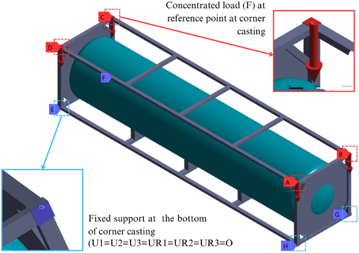
Clamped boundary conditions are applied at the bottom corners, and concentrated force is set at the top corners.
In the current ISO tank model, fixed support interaction is employed on the tank model related to the frame model. The purpose of using fixed support interaction is to bind points on the surfaces that meet each other. Visualization of these constraints is displayed in Figure 5. These constraints consist of three areas: the connection between the front and rear tanks using check plates. These bounding constraints ensure a robust and reliable connection with a face-to-edge contact. The face-to-edge contact type allows for effective interaction in various conditions. Second, the contact connects the lower cylinder tank to the saddle via face-to-face connections. This constraint ensures a strong and consistent interaction between the tank and saddle, enabling proper load transfer. Third, the connection of the Bakelite support with the inner shell through edge-to-face contacts ensures that the Bakelite support has effective and robust interaction as the primary support connecting the inner shell with the outer shell.
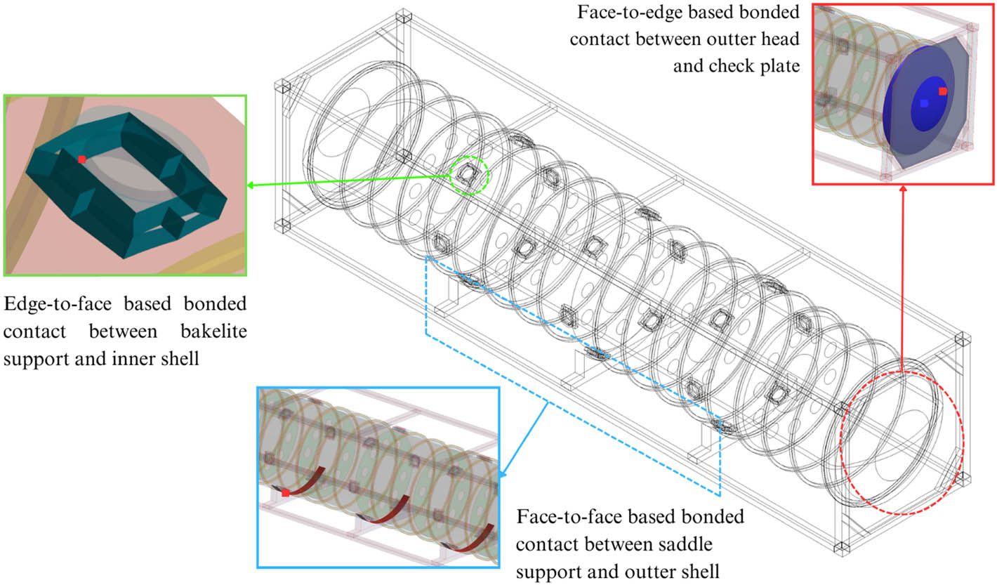
Constraints between saddle support and outer shell (blue), outer head and check plate (red), and Bakelite support and inner shell (green).
2.3.3 Mesh convergence analysis
The ideal mesh size is guaranteed by mesh convergence analysis, which improves computing efficiency [35]. Reducing the mesh size or increasing the density of already existing nodes can accomplish mere refinement. The initial study aims to establish the ideal mesh size under different load scenarios by analyzing the structural displacement response. As shown in Figure 6, FEA simulations are carried out using quadrilateral mesh sizes ranging from 30 to 90 mm. The Ansys Meshing Tool is used in this simulation’s meshing process, and shell components are used to discretize the model. Figure 7 explains how convergence is effectively achieved with a 40 mm mesh size with total of 196,032 elements.
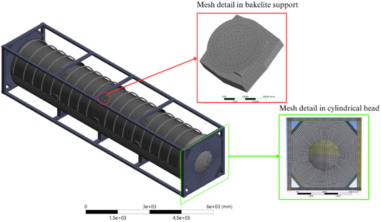
Mesh detail on the pressure vessel of the ISO tank.
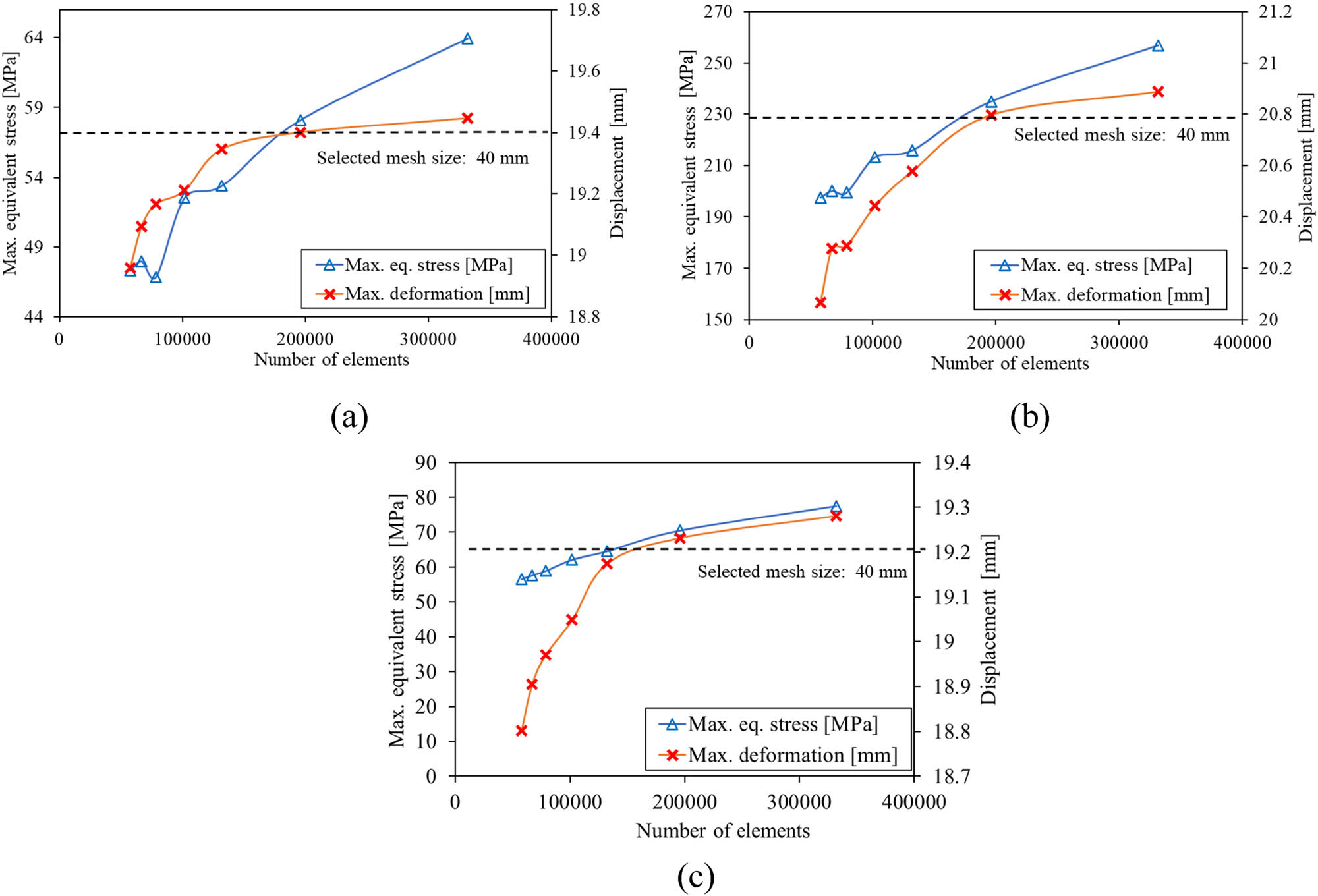
Convergence assessment in various loading scenarios: (a) lifting, (b) stacking, and (c) transverse racking.
2.3.4 Design variation of Bakelite support
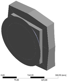
The pressure vessel and the frame structure are the two primary parts of the LNG ISO tank. Saddles, corner fittings, and end structures are parts of the frame structure that transfer forces generated during lifting and handling operations. The inner and outer tanks, heads or covers, baffles, stiffener rings, Bakelite support, and Bakelite cover make up the pressure vessel. The geometry of the reference model is referred to in an earlier study conducted by BRIN [17], as seen in Figure 8.
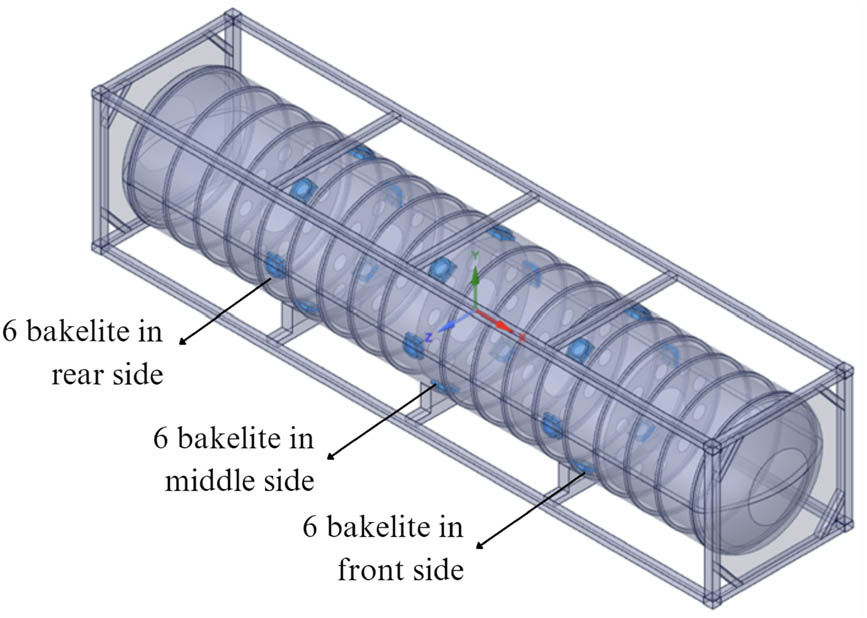
Location of Bakelite support in the 40 ft ISO LNG tank.
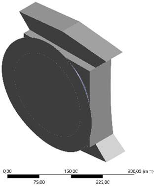
Optimization is conducted on the Bakelite support to eliminate components far from the critical stress without decreasing the structural integrity of the pressure vessel. The optimized Bakelite support region is indicated in Figure 9 by the blue-colored part. The blue area is the optimization region. The redesign process involves modeling ISO 1496 operational loading.

Optimization area on the Bakelite support of the pressure vessel.
3 Results and discussion
This section presents the results of the FEA conducted for the topology optimization of the Bakelite support in the LNG ISO tank. Section 3.1 provides the baseline FEA results for the intact, pre-optimization design. Section 3.2 discusses the outcomes of the topology optimization under varying mass retention levels. Subsequently, Section 3.3 evaluates the structural performance of the redesigned Bakelite support to assess the overall strength and integrity of the optimized LNG ISO tank configuration.
3.1 Structural strength of the intact LNG ISO tank design
Three loading scenarios were utilized in this simulation study: lifting, stacking, and racking (transversal). The simulation results are divided into three main sections: the ISO LNG tank frame structure, the pressure vessel, and the Bakelite support. Table 4 presents data on stress values, deformation, and safety factors for each 40 ft ISO LNG tank section under each loading scenario. Figure 10 illustrates the simulation results regarding safety factor values for each loading scenario. It is evident that among the structural components and loading scenarios, the ISO LNG tank frame structure exhibits the lowest safety factor compared to the pressure vessel and Bakelite support because the ISO LNG tank frame structure is the primary support for the tank and its load. Despite having the lowest safety factor, the stress values in the ISO LNG tank frame structure remain below the yield strength of the steel material, which is 340 MPa. In contrast, the stress in the Bakelite support is the lowest due to its design as a reinforcing structure that connects and supports the inner and outer tanks, bearing the internal forces exerted by the cargo, thereby ensuring support without compromising the tank’s structural integrity.
Comparison of FEA results in the existing model in all load scenarios
| Load scenario | Max equiv. stress (MPa) | Displacement (mm) | Safety factor | ||||||
|---|---|---|---|---|---|---|---|---|---|
| Structural frame | Pressure vessel | Bakelite support | Structural frame | Pressure vessel | Bakelite support | Structural frame | Pressure vessel | Bakelite support | |
| Lifting | 58.12 | 21.01 | 21.01 | 19.40 | 0.35 | 0.34 | 1.48 | 8.09 | 8.09 |
| Stacking | 234.99 | 51.56 | 21.13 | 20.80 | 1.23 | 1.22 | 1.44 | 3.29 | 8.04 |
| Racking (transverse) | 70.57 | 21.23 | 21.23 | 19.23 | 0.57 | 0.56 | 1.22 | 9.01 | 8.01 |
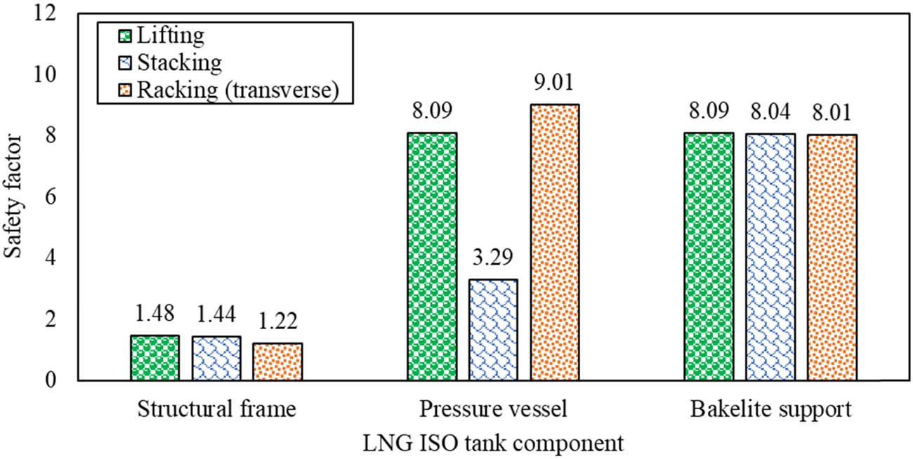
Comparison of the safety factor values for the ISO LNG tank under loading scenario.
Among the three loading scenarios used in the simulation, stacking was the most critical loading condition compared to the lifting and racking scenarios. Stacking became the most vital loading condition because the LNG ISO tank experienced excessive stacking loads in real-world conditions; the ISO tank is treated differently from ordinary cargo containers and can only be stacked up to a maximum of two levels. Previous research has demonstrated the same result [8,17,36].
Figure 11 shows the contour of maximum stress in the LNG ISO tank 40 ft for each loading scenario. In the stacking loading scenario, the greatest stress value was observed to be 234.99 MPa, precisely at the intersection of the vertical and upper horizontal frames of the frame structure. Since this component immediately interacts with the ISO corner casting, which serves as the load-bearing center, the point of maximum stress value essentially stands at the intersection of the vertical frame and the upper horizontal frame of the frame structure. As can be seen, the vertical frame in the LNG ISO tank 40 ft has the highest critical value when compared to other parts.

Maximum equivalent stress contour of the LNG ISO 40 ft tank in each loading scenario: (a) lifting, (b) stacking, and (c) transverse racking.
Figure 12 depicts the simulation results as maximum displacement values for each loading scenario. It was observed that among the structural components and loading scenarios, the LNG ISO tank’s frame structure exhibited the highest displacement level compared to the pressure vessel and the Bakelite support. Meanwhile, Figure 13 illustrates each loading scenario’s LNG ISO tank 40 ft displacement contour. The stacking loading scenario found the highest displacement value, reaching 20.79 mm. The maximum displacement value was located in the longitudinal frame due to the transverse force direction on the end frame, making the longitudinal frame critical for maintaining structural integrity.
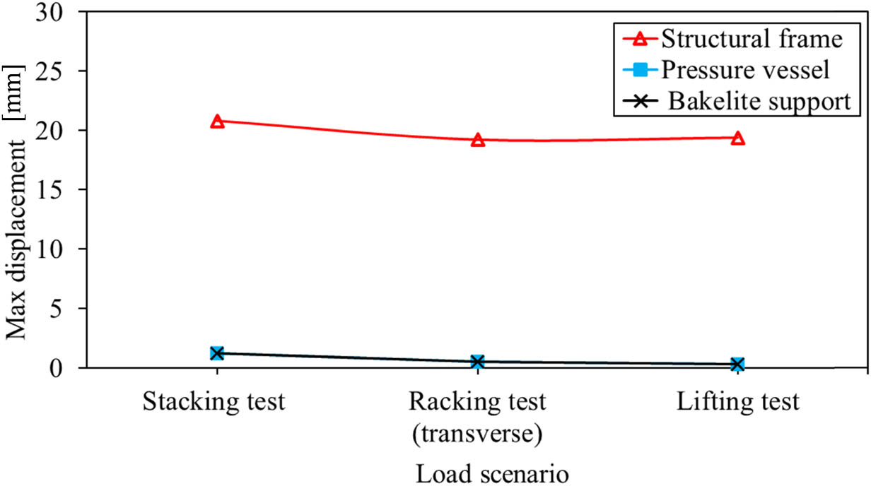
Maximum displacement values of different structural parts in each loading scenario.
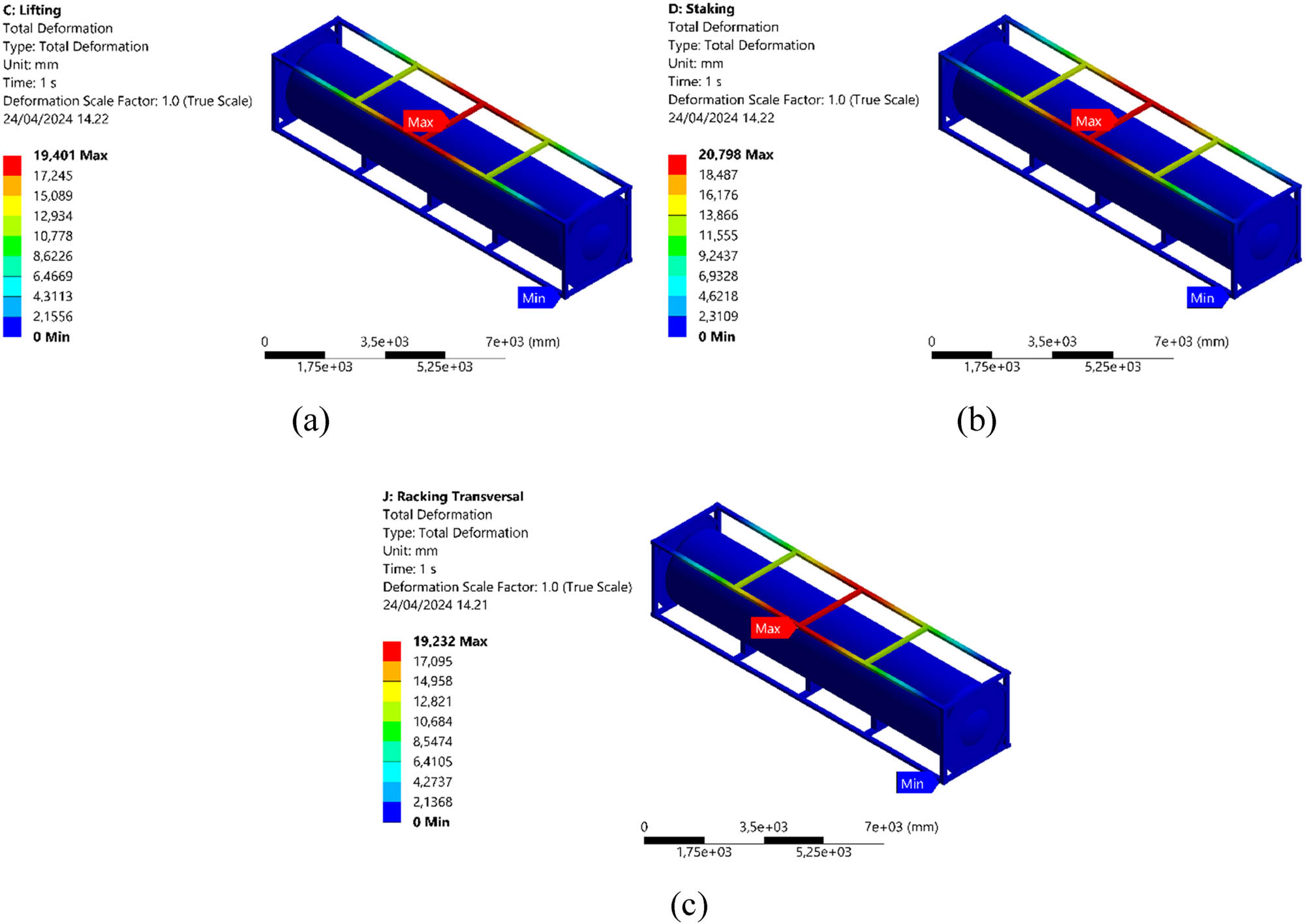
Maximum displacement contour of the LNG ISO 40 ft tank in each loading scenario: (a) Lifting, (b) stacking, and (c) transverse racking.
3.2 Result of topology optimization of Bakelite design
Based on the simulation results, the frame structure of the LNG ISO tank exhibited the highest stress values but remained below the material’s allowable stress limit. In contrast, the Bakelite support had the lowest stress values among the three components: the frame structure of the LNG ISO tank, the pressure vessel, and the Bakelite support. The optimization process in this study focused on the Bakelite support. This area was the optimization process’s primary focus, known as the optimization region in the Ansys structural optimization software. The mass range maintained in the topology optimization was set from 50 to 90%, and strain energy was monitored for each simulation.
Table 5 illustrates the optimization results for the retained mass and presents five optimization outcomes for the Bakelite support design, showing the removal of several geometric sections. The mass retains optimization results, ranging from 90 to 50%, leading to a significant reduction in the weight of the Bakelite support, with a weight reduction percentage of 4.81–81.41% from the initial weight of 291.13 kg. Redesigning the quantity and geometry of the model is crucial for modifying the quantity and geometry of the Bakelite support. The results of the redesign in terms of quantity and geometry of the Bakelite support model are presented in Table 6. Significant changes can be observed in the central Bakelite support; with retained mass ranging from 80 to 50%, this section is eliminated, leaving Bakelite supports with various geometries on the right and left sides of the ISO LNG tank.
Optimization results of Bakelite support for each mass retain
| Mass retained (%) | Result of Bakelite design optimization | Bakelite weight (kg) |
|---|---|---|
| 90 |

|
277.13 |
| 80 |

|
157.13 |
| 70 |

|
129.13 |
| 60 |

|
104.13 |
| 50 |

|
54.13 |
Results of proposed geometry redesign of Bakelite support models
| Mass retained (%) | 3D Bakelite support redesign model | Total of Bakelite support |
|---|---|---|
| 90 |

|
18 |
| 80 |
|
12 |
| 70 |

|
12 |
| 60 |
|
12 |
| 50 |
|
12 |
3.3 Results of optimized design of LNG ISO tank structure
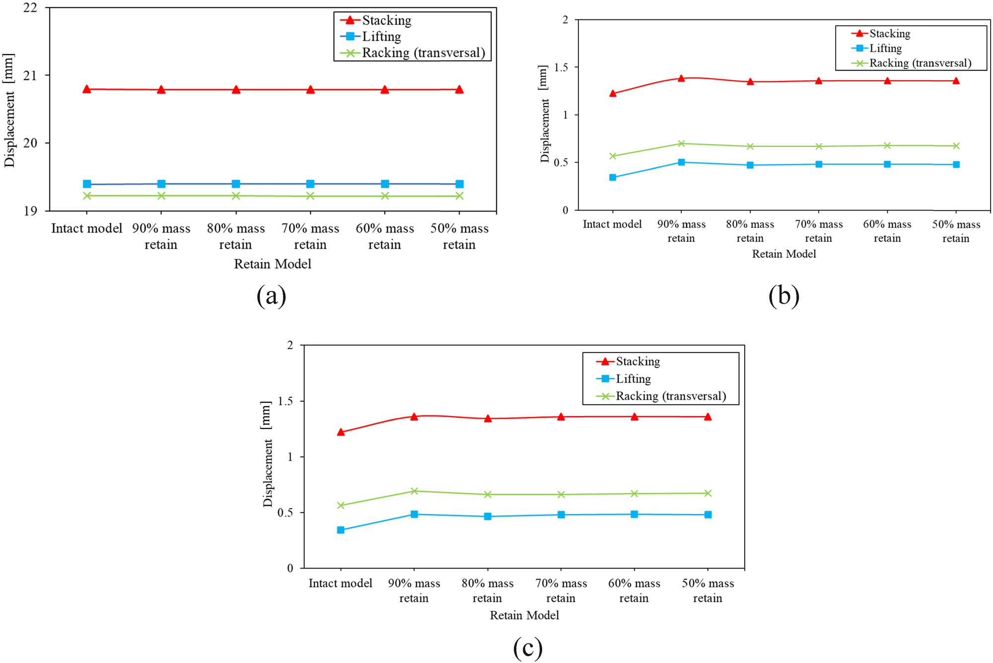
Table 7 displays the simulation results, which compare the maximum stress and displacement in the structural frame of the LNG ISO tank, pressure vessel, and Bakelite support under different loading scenarios and retained masses due to the optimized model. A comparison of the stress levels in each component of the redesigned model with Bakelite support and the original ISO LNG tank model is shown in Figure 14. It can be found that the maximum stress value in the ISO LNG tank frame structure exhibited results comparable to the original model before the optimization of the Bakelite support. Under the stacking loading scenario, the pressure vessel section showed values that tended to stabilize with the stress values of the initial model, ranging from 51.48 to 51.53 MPa. However, the Bakelite support and pressure vessel exhibited an increase in stress compared to the initial model at lifting and racking load.
Maximum equivalent stress and displacement values of the redesigned model at different loading scenarios
| Load scenario | Mass retained (%) | Max equiv. stress (MPa) | Displacement (mm) | ||||
|---|---|---|---|---|---|---|---|
| Structural frame | Pressure vessel | Bakelite support | Structural frame | Pressure vessel | Bakelite support | ||
| Lifting | 90 | 57.62 | 25.79 | 25.79 | 19.40 | 0.50 | 0.48 |
| 80 | 57.62 | 34.64 | 34.64 | 19.40 | 0.47 | 0.47 | |
| 70 | 57.62 | 39.03 | 39.03 | 19.40 | 0.48 | 0.48 | |
| 60 | 57.62 | 41.59 | 41.59 | 19.40 | 0.48 | 0.48 | |
| 50 | 57.62 | 42.13 | 42.13 | 19.40 | 0.48 | 0.48 | |
| Stacking | 90 | 234.99 | 51.53 | 25.01 | 20.80 | 1.39 | 1.36 |
| 80 | 234.99 | 51.52 | 34.14 | 20.80 | 1.35 | 1.34 | |
| 70 | 234.99 | 51.49 | 38.41 | 20.80 | 1.36 | 1.36 | |
| 60 | 234.99 | 51.51 | 40.88 | 20.80 | 1.36 | 1.36 | |
| 50 | 234.99 | 51.48 | 45.02 | 20.80 | 1.36 | 1.36 | |
| Racking (transversal) | 90 | 70.56 | 26.09 | 26.09 | 19.23 | 0.70 | 0.69 |
| 80 | 70.56 | 36.06 | 36.06 | 19.23 | 0.67 | 0.66 | |
| 70 | 70.56 | 40.68 | 40.68 | 19.23 | 0.67 | 0.66 | |
| 60 | 70.56 | 42.40 | 42.40 | 19.23 | 0.68 | 0.67 | |
| 50 | 70.56 | 42.89 | 42.89 | 19.23 | 0.68 | 0.67 | |
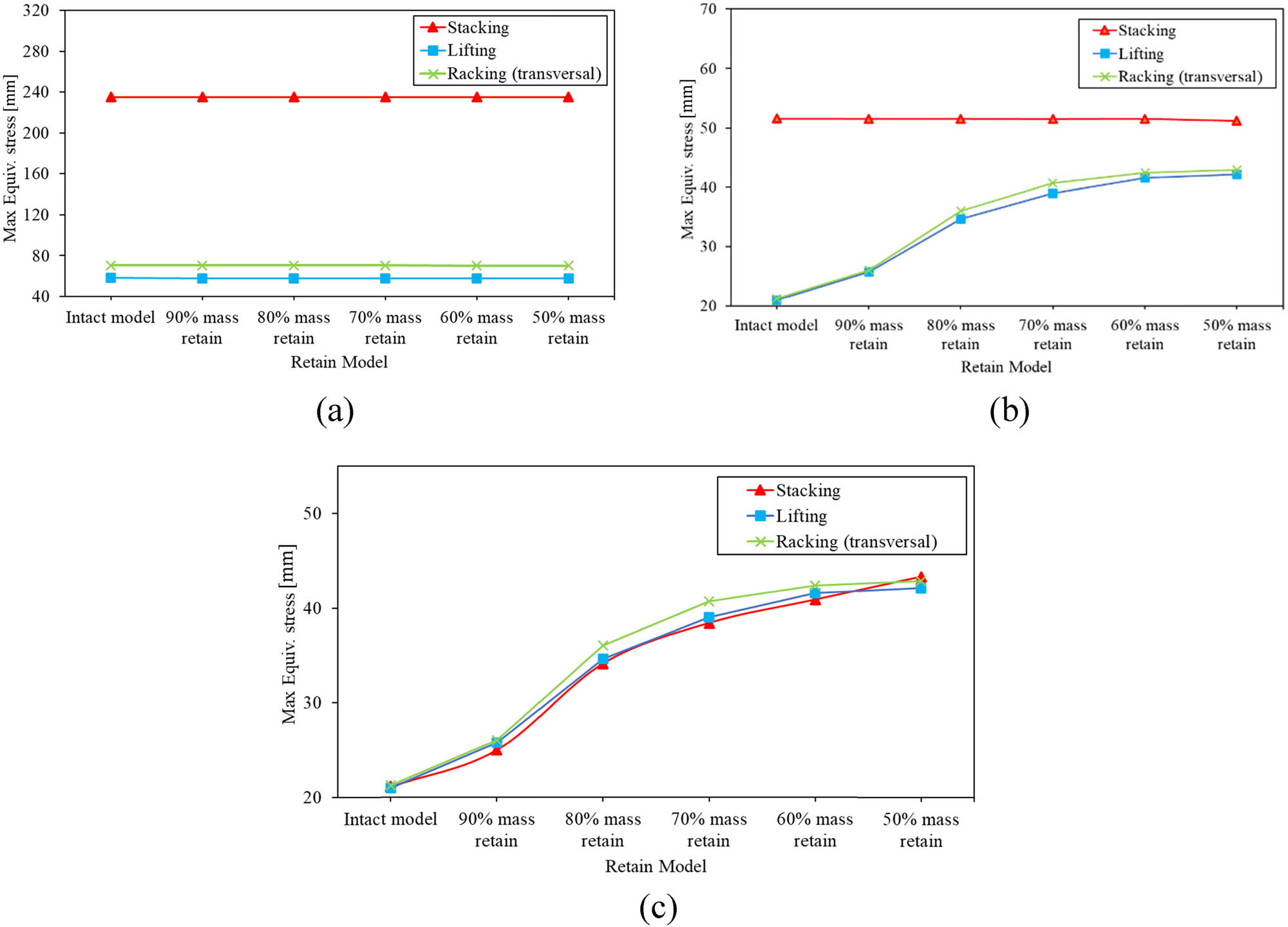
Maximum equivalent stress values between intact and optimized models for each component: (a) structural frame, (b) pressure vessel, and (c) Bakelite support.
Figure 15 compares the maximum displacement values between the initial ISO LNG tank and the optimized model with Bakelite support in each component. The maximum displacement value in the ISO LNG tank frame structure showed results similar to the initial model’s displacement value at 20.80 mm. The displacement values of the pressure vessel section and Bakelite support exhibited a similar trend in each loading scenario, experiencing a slight increase compared to the initial model and maintaining a stable value in each mass retain.
Maximum displacement values between intact and optimized models: (a) Structural frame, (b) pressure vessel, and (c) Bakelite support.
Figure 16 depicts the result of maximum stress distribution from the initial and redesigned models in the stacking loading scenarios. The model with Bakelite support mass retained at 50–90% exhibited the highest maximum stress values in the structural frame of the 40 ft ISO LNG tank. The maximum stress was distributed in the vertical frame among the five redesigned models with Bakelite support. Meanwhile, the Bakelite support, which underwent a redesign with retained mass ranging from 50 to 90%, exhibited low maximum stress values, sequentially measuring 45.02–25.01 MPa, compared to the initial design stress value of 21.13 MPa. These results indicated that the smaller the retained mass in the Bakelite support, the greater the maximum stress increase due to removing more elements.
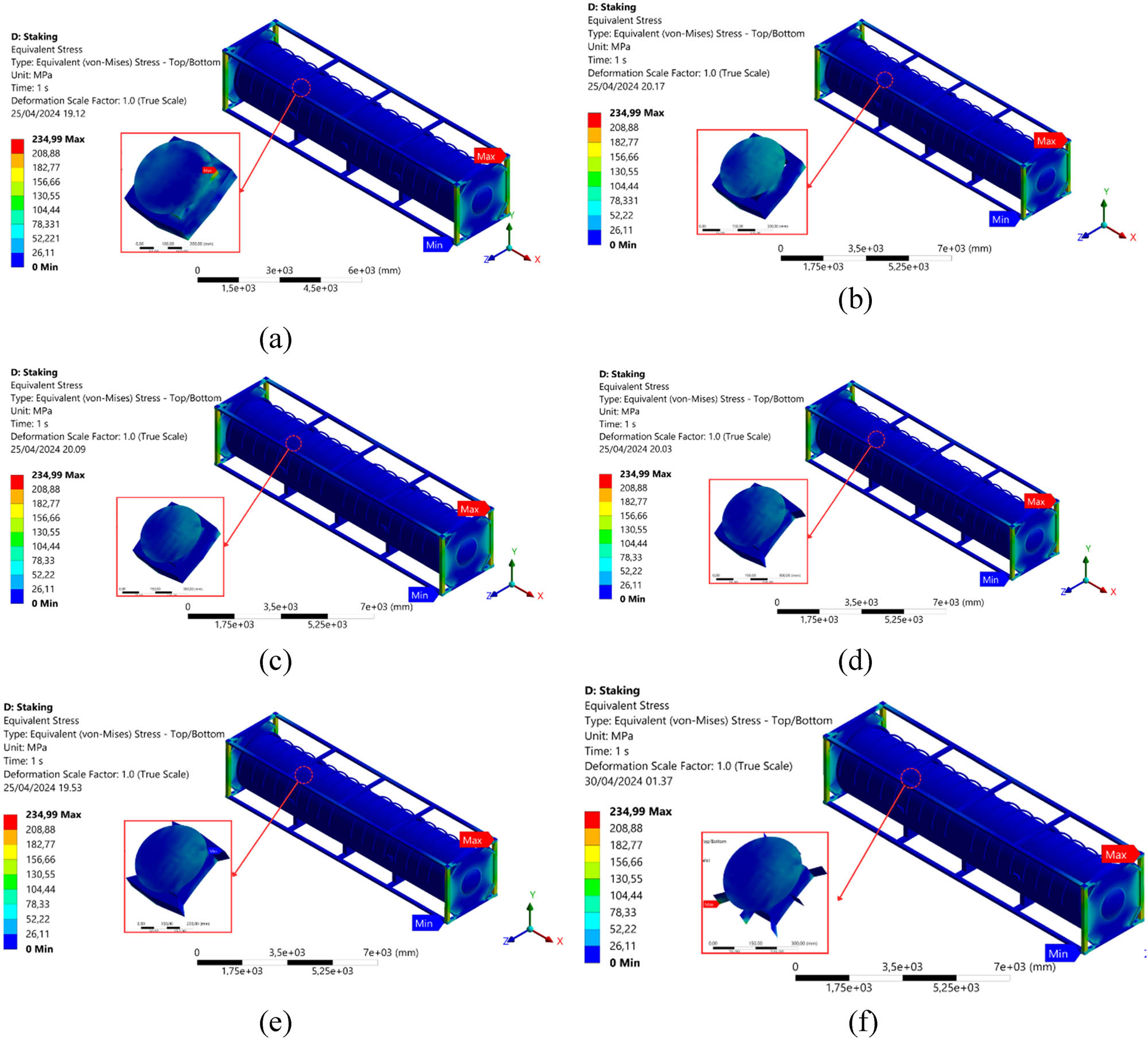
Stress contour of the stacking loading on the LNG ISO 40 ft tank and Bakelite support for each mass retain model: (a) Intact model, (b) 90%, (c) 80%, (d) 70%, (e) 60%, and (f) 50%.
Figure 17 illustrates the displacement distribution of the initial and redesigned models in the stacking loading scenario. The model with Bakelite support mass retained at 50–90% exhibited the highest displacement in the structural frame of the 40 ft ISO LNG tank, specifically in the top transverse frame. Meanwhile, the Bakelite support, which underwent a redesign with retained mass ranging from 50 to 90%, maintained a constant displacement value of 20.79 mm. It demonstrated that the topology optimization process did not significantly impact the displacement values.
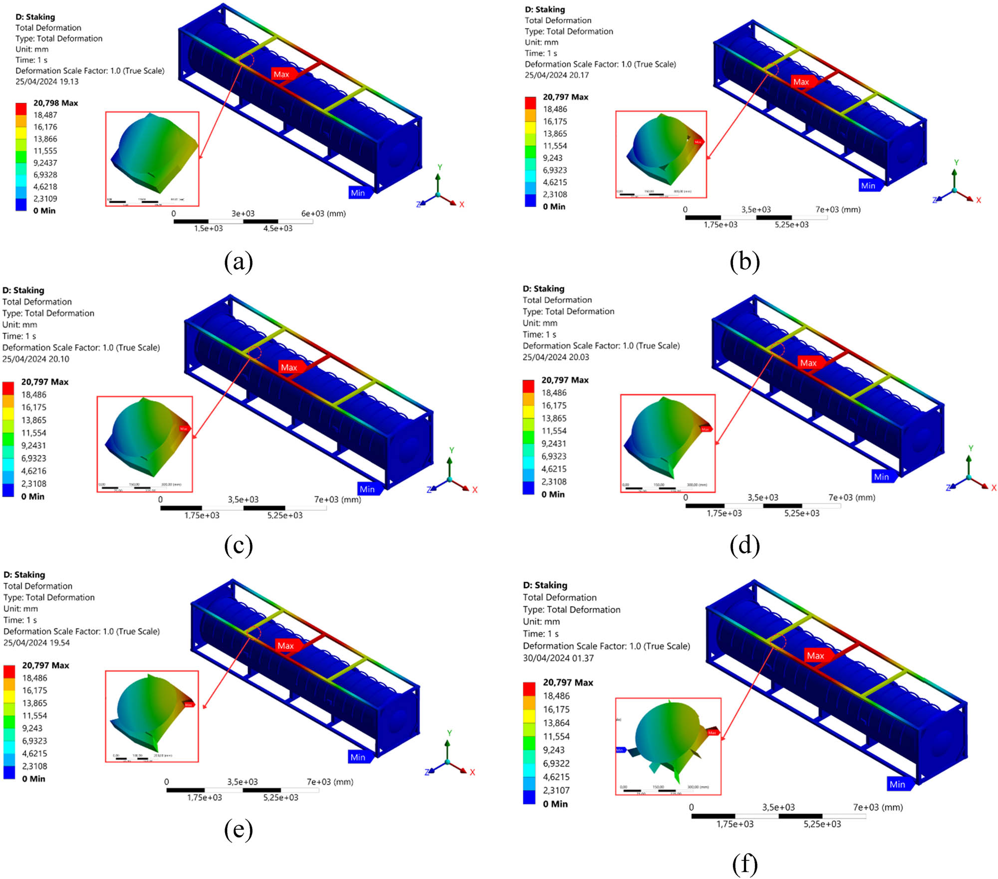
Displacement contour of the stacking loading on the LNG ISO 40 ft tank and Bakelite support for each mass retain the model of the LNG ISO 40 ft tank: (a) Intact model, (b) 90%, (c) 80%, (d) 70%, (e) 60%, and (f) 50%.
Figure 18 compares the total weight of the ISO LNG tank between the initial ISO LNG tank model and the redesigned ISO LNG tank model with optimized design of Bakelite support. It can be found that the less mass retained, the greater the mass removed from the model. As shown in Figure 18, the total weight reduction of the redesigned ISO LNG tank from the initial weight of 16.60 kg decreases to 16.36 kg. The reduction in the total weight of the ISO LNG tank for each retained mass does not cause a substantial increase in the stress values throughout the tank structure. The percentage reduction in the total weight of the ISO LNG tank, ranging from 0.08 to 1.43%, occurs because the geometry of the Bakelite support is small. Thus, its impact on the change in the total mass of the ISO LNG tank is insignificant.
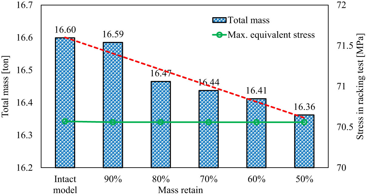
Comparison between overall mass and stress value between intact and optimized models.
4 Conclusion
A series of topology optimization studies on a 40 ft ISO LNG tank has been conducted using Ansys Structural Topology to produce a Bakelite support design that optimizes weight savings and structural performance under operational loading conditions. The retained mass is the objective function, ranging from 90 to 50%, and is analyzed across three operational loading scenarios based on ISO 1496 standards. An initial analysis of ISO 1496 loading scenarios identified stacking as the most critical condition for the 40 ft ISO LNG tank frame. It can be found that design optimization of the Bakelite support structure resulted in a substantial Bakelite weight reduction of 4.81–81.41%. The proposed optimization strategy is found by removing the Bakelite support in the middle area of the pressure vessel. Although the optimized design slightly increased stress within the pressure vessel and Bakelite supports, it achieved an overall weight reduction of up to 1.43% with experienced stress below the limit criteria.
Topology optimization of the Bakelite support is approved in maintaining structural integrity while minimizing weight. Further investigations are recommended to optimize the geometry and distribution of other tank components, such as the frame and saddle support, aligned with ISO 1496 loading scenarios.
Acknowledgments
The authors would like to thank the Laboratory of Ship Strength and Material, Department of Naval Architecture at Universitas Diponegoro, for providing the facility to conduct the numerical simulation.
-
Funding information: The authors thank the RISPRO-LPDP Ministry of Finance of the Republic of Indonesia for funding this research through the Research and Innovation for Advanced Indonesia (RIIM) 2024 with contract number B-839/II.7.5/FR.06/5/2023.
-
Author contributions: All authors have accepted responsibility for the entire content of this manuscript and consented to its submission to the journal, reviewed all the results, and approved the final version of the manuscript. T.T., R.F.T., O.M., and N.R. conceived the presented idea, developed the theory, and performed the computations. A.A., Y.Y., I.E.S., and A.M. verified the numerical methods. D.P.S., R.H., M.R.U., and T.M. supervised the findings of this entire work. All authors discussed the results and contributed to the final manuscript.
-
Conflict of interest: The authors state no conflict of interest.
-
Ethical approval: This work does not contain any experiments with human participants or animals undertaken.
-
Data availability statement: The data supporting this study will be made available upon reasonable request.
References
[1] Nuswantara MP, Wiryawan Wibawa G. Regasification of LNG (Liquefied Natural Gas). J Teknik Pomits. 2014;3(2):149–52.Suche in Google Scholar
[2] ICTO. Global tank container fleet survey 2021. Surbiton, United Kingdom: International Tank Container Organisation; 2021. p. 1–15.Suche in Google Scholar
[3] Pham VC, Choi JH, Rho BS, Kim JS, Park K, Park SK, et al. A numerical study on the combustion process and emission characteristics of a natural gas-diesel dual-fuel marine engine at full load. Energies (Basel). 2021;14(5):1–28.10.3390/en14051342Suche in Google Scholar
[4] Santoso NB, Pemanfaatan LNG. Sebagai Sumber Energi di Indonesia. J Rekayasa Proses. 2014;8(1):33–9.Suche in Google Scholar
[5] Wibowo YE, Windarta J. Kondisi Gas Bumi Indonesia dan Energi Alternatif Pengganti Gas Bumi. J Energi Baru dan Terbarukan. 2022;3(1):1–14.10.14710/jebt.2022.10042Suche in Google Scholar
[6] Herdzik J. LNG as a marine fuel - possibilities and problem. J KONES. 2011;18(2):169–76.Suche in Google Scholar
[7] Clause-by-Clause analysis of MARPOL Annex VI. London, United Kingdom: IMO; 2018.Suche in Google Scholar
[8] Masbar Rus AM, Pramudita R, Surjandari I. Segmentation of natural gas customers in industrial sector using self-organizing map (SOM) method. IOP Conf Ser Mater Sci Eng. 2018;316(1):1–9.10.1088/1757-899X/316/1/012046Suche in Google Scholar
[9] Mokhatab S, Mak JY, Valappil DAWJV, eds. Handbook of liquefied natural gas. Buku Pegangan Gas Alam Cair. Oxford, Great Britain: Gulf Professional Publishing; 2014. p. 1–106.Suche in Google Scholar
[10] Uemura T, Ishigami K. Formulating policy options for promoting natural gas utilization in the East Asia summit region: Volume II - Supply side analysis. Vol. II. Jakarta, Indonesia: Economic Research Institute for ASEAN and East Asia; 2018. p. 100.Suche in Google Scholar
[11] Marpaung F, Wibowo ET, Harmadi R. Desain dan Analisis Tanki ISO LNG Kapasitas 40 feet Menggunakan Teknik finite element analysis. J Asiimetrik: J Ilm Rekayasa Inov. 2022;4:163–70.Suche in Google Scholar
[12] Lee DY, Jo JS, Nyongesa AJ, Lee WJ. Fatigue analysis of a 40 ft LNG ISO tank container. Materials. 2023;16(1):1–12.10.3390/ma16010428Suche in Google Scholar PubMed PubMed Central
[13] ASME. ASME boiler and pressure vessel code section VIII division 1. New York: ASME; 2019. p. 796.Suche in Google Scholar
[14] Il Park Y, Cho JS, Kim JH. Structural integrity assessment of independent type-C cylindrical tanks using finite element analysis: Comparative study using stainless steel and aluminum alloy. Metals (Basel). 2021;11:1–19.Suche in Google Scholar
[15] Muttaqie T, Sasmito C, Iskendar, Kadir A. Structural strength assessment of 20-ft LNG ISO tank: An investigation of finite element analysis and ASME design guidance. IOP Conf Ser Earth Environ Sci. 2022;972(1):1–13.10.1088/1755-1315/972/1/012015Suche in Google Scholar
[16] Marpaung F, Wibowo ET, Harmadi R. Desain dan Analisis Tanki ISO LNG Kapasitas 40 feet Menggunakan Teknik finite element analysis. J Asiimetrik: J Ilm Rekayasa Inov. 2022;4:163–70.10.35814/asiimetrik.v4i1.2989Suche in Google Scholar
[17] Purnamasari D, Tuswan T, Muttaqie T, Sandjaja IE, Machfudin A, Rizal N, et al. Structural assessment of 40 ft mini LNG ISO tank: Effect of structural frame design on the strength performance. Curved Layer Struct. 2024;11:1–29.10.1515/cls-2022-0219Suche in Google Scholar
[18] Lakshmikanth Chowdary V. Design and static analysis of different pressure vessels and materials using FEM method. Int J. 2020;5(7):93–9.Suche in Google Scholar
[19] Wang Z, Qian C. Strength analysis of LNG tank container for trains under inertial force. J Phys Conf Ser. 2020;1549(3):1–6.10.1088/1742-6596/1549/3/032107Suche in Google Scholar
[20] Liu J. Strength analysis of the tank container based on ANSYS. Petro Ind Tech. 2019;26:82–4 + 90.Suche in Google Scholar
[21] Zhaochun R, Ying L, Chao H. Stress analysis of LNG tank container. Ref Chem Ind. 2018;29(42):3.Suche in Google Scholar
[22] Qiu W, Gao C, Sun L, Luo R. Research on topology optimization method for tanker structures in cargo tank region. TSCF 2016 shipbuilders meeting. South Korea: Tanker Structure Co-operative Forum; 2016. p. 1–18.Suche in Google Scholar
[23] Insano S, Rochardjo HSB. Optimasi Desain Struktur Train Nose Frame dengan Finite Element Analysis. KONSTELASI: Konvergensi Teknologi dan Sist Inf. 2023;3(1):73–84.10.24002/konstelasi.v3i1.7089Suche in Google Scholar
[24] Nugraha DP, Suryo SH, Mesin DT, Teknik F, Diponegoro U. Optimasi Desain Topologi Struktur Boom Excavator CAT 374D L Dengan Menggunakan Metode Elemen Hingga. J Teknik Mesin. 2022;10(3):385–92.Suche in Google Scholar
[25] Huda N, Mursid O, Nurfauzi A. Studi Optimasi Topologi Pada Fall Block Deck Crane Kapasitas 30 Ton Menggunakan Metode Elemen Hingga. Media Mesin: Maj Teknik Mesin. 2022;23(1):20–7.10.23917/mesin.v23i1.15940Suche in Google Scholar
[26] Tuswan T, Andrian M, Amiruddin W, Muttaqie T, Sari DP, Bisri A, et al. Design improvement using topology optimization for the structural frame design of a 40 Ft LNG ISO container tank. Designs (Basel). 2024;8(2):21.Suche in Google Scholar
[27] Yang XY, Xie YM, Steven GP, Querin OM. Topology optimization for frequencies using an evolutionary method. J Struct Eng. 1999;125(12):1432–8.10.1061/(ASCE)0733-9445(1999)125:12(1432)Suche in Google Scholar
[28] International Organization for Standardization. SO 1496-3: Series 1 freight containers–Specification and testing–Part 3, Tank containers for liquids, gases, and pressurized dry bulk. Geneva, Switzerland: ISO; 1995.Suche in Google Scholar
[29] ASME. SECTION II materials - ASME boiler and pressure vessel code. New York: ASME; 2019. p. 1–1262.Suche in Google Scholar
[30] ASME. ASME boiler and pressure vessel code section II part D properties. New York: ASME; 2019.Suche in Google Scholar
[31] Giriunas K, Sezen H, Dupaix RB. Evaluation, modeling, and analysis of shipping container building structures. Eng Struct. 2012;43:48–57.10.1016/j.engstruct.2012.05.001Suche in Google Scholar
[32] International Organization for Standardization. Series 1 freight containers – Classification, dimensions and ratings (ISO Standard No. 668:2020). 2020;2020:1–17.Suche in Google Scholar
[33] Fahy M, Tiernan S. Finite element analysis of ISO tank containers. J Mater Process Technol. 2001;119(1–3):293–8.10.1016/S0924-0136(01)01034-2Suche in Google Scholar
[34] Il Park Y, Cho JS, Kim JH. Structural integrity assessment of independent type-C cylindrical tanks using finite element analysis: Comparative study using stainless steel and aluminum alloy. Metals (Basel). 2021;11:1–20.10.3390/met11101632Suche in Google Scholar
[35] Prabowo AR, Laksono FB, Sohn JM. Investigation of structural performance subjected to impact loading using finite element approach: Case of ship-container collision. Curved Layer Struct. 2020;7(1):17–28.10.1515/cls-2020-0002Suche in Google Scholar
[36] Tuswan T, Andrian M, Amiruddin W, Muttaqie T, Sari DP, Bisri A, et al. Design improvement using topology optimization for the structural frame design of a 40 Ft LNG ISO container tank. Designs (Basel). 2024;8(2):21.10.3390/designs8020021Suche in Google Scholar
© 2025 the author(s), published by De Gruyter
This work is licensed under the Creative Commons Attribution 4.0 International License.
Artikel in diesem Heft
- Research Articles
- Layerwise generalized formulation solved via a boundary discontinuous method for multilayered structures. Part 1: Plates
- Thermoelastic interactions in functionally graded materials without energy dissipation
- Layerwise generalized formulation solved via boundary discontinuous method for multilayered structures. Part 2: Shells
- Visual scripting approach for structural safety assessment of masonry walls
- Nonlinear analysis of generalized thermoelastic interaction in unbounded thermoelastic media
- Study of heat transfer through functionally graded material fins using analytical and numerical investigations
- Analysis of magneto-aerothermal load effects on variable nonlocal dynamics of functionally graded nanobeams using Bernstein polynomials
- Effective thickness of gallium arsenide on the transverse electric and transverse magnetic modes
- Investigating the behavior of above-ground concrete tanks under the blast load regarding the fluid-structure interaction
- Numerical study on the effect of V-notch on the penetration of grounding incidents in stiffened plates
- Thermo-elastic analysis of curved beam made of functionally graded material with variable parameters
- Effect of curved geometrical aspects of Savonius rotor on turbine performance using factorial design analysis
- A mechanical and microstructural investigation of friction stir processed AZ31B Mg alloy-SiC composites
- Mechanical design of engineered-curved patrol boat hull based on the geometric parameters and hydrodynamic criteria
- Analysis of functionally graded porous plates using an enhanced MITC3+ element with in-plane strain correction
- Review Article
- Technological developments of amphibious aircraft designs: Research milestone and current achievement
- Special Issue: TS-IMSM 2024
- Influence of propeller shaft angles on the speed performance of composite fishing boats
- Design optimization of Bakelite support for LNG ISO tank 40 ft using finite element analysis
- The topology optimization applied to the evaluation study of bracket caliper by using finite element method