Investigating the behavior of above-ground concrete tanks under the blast load regarding the fluid-structure interaction
-
 ,
,

Abstract
The possibility of damage caused by explosive loading in above-ground tanks due to not being covered is much higher compared to buried and semi-buried concrete and steel tanks. In order to evaluate the real behavior of above-ground tanks, it is necessary to pay attention to fluid and structure interaction. Therefore, investigating the behavior of above-ground tanks under the blast load, taking into account the effects of fluid-structure interaction is the main goal of the study. For this purpose, the main variables are the amount of fluid in the tank (empty, half full, and full) and the distribution of fluid pressure on the tank (uniform and nonuniform pressure). Also, the investigated responses include maximum von Mises stress, maximum displacement created in the tank, kinetic energy, and failure index. The results show that considering the tank as empty of fluid, increased the responses of maximum stress, maximum displacement, kinetic energy, and failure index by 18.1, 31.2, 4.1, and 17%, respectively. Also, filling the tank with fluid has caused a decrease of 41, 90, 8.9, and 15.4% in the responses of maximum distributed stress, maximum displacement, kinetic energy, and failure index of the tank, respectively. Other results show that the nonuniform distribution of fluid pressure in the tank increases the maximum responses of stress and failure index in the tank by 35.6 and 2.5%, respectively. In this condition, the maximum responses of displacement and kinetic energy decrease by 84.3 and 4.3%, respectively.
1 Introduction
The possibility of damage caused by explosive loading in above-ground tanks due to not being covered is much higher compared to buried and semi-buried concrete or steel tanks. In order to evaluate the real behavior of above-ground tanks, it is necessary that fluid and structure interaction to be considered. In general, the interaction between the fluid and the structure results from the two phenomena of the inability of the structure to follow the changes in the shape of the fluid and the dynamic effect of the structure on the movement of the fluid. Therefore, regarding the above-ground tanks and according to the type of loading applied to the structure (blast load), the above-ground tanks are interacting with the fluid inside them. Thus, in the dynamic analysis of above-ground tanks, by considering the mentioned interaction, the obtained results will be more realistic and practical. Therefore, ignoring the effects of fluid and structure interaction, especially in the great structures such as above-ground tanks can lead to a wrong analysis of the structure’s behavior and finally obtaining unrealistic and unexpected responses. It should be noted that in this study, the pressure caused by the fluid on the tank in two states of rectangular (uniform) and triangular (nonuniform) distribution in empty, half-full, and full tanks has been investigated and evaluated.
Above-ground concrete water tanks are usually built in cylindrical and rectangular cube shapes, although they can be built in any beautiful and appropriate geometric shape. In general, cylindrical tanks are superior to rectangular cubic tanks in terms of technical and passive defense considerations. In the areas where the soil load factor is suitable, bowl tanks are also a suitable option for large volumes. From the point of view of serviceability and passive defense considerations, tanks are usually considered as twins. But if there are no special limitations, the most economic geometric dimensions for rectangular cube tanks are obtained when the ratio of the length to the width of the tank is 3 to 2. About the twin cylindrical tanks, the best mode is to use two independent tanks with equal volume [1]. In practice, in order to save money and time for the analysis and design of the tanks, codes, and analytical relationships are used. These code relationships are mainly based on mechanical models. The most famous mechanical models are [2]: (1) two-mass model of Hausner, (2) three-mass model of Haroun, and (3) simple method of Malhotra.
Rectangular and circular concrete tanks with fix and flexible foundations, as well as air tanks with supporting foundations are considered at ACI350.3. In NZSEE code, circular and rectangular concrete ground tanks with rigid and flexible foundations, as well as concrete air tanks are considered and evaluated. In Euro code 8, circular and rectangular tanks with girder base and air tanks have been evaluated. Also, in Iranian code named publication 123, concrete circular and rectangular concrete tanks have been analyzed and investigated in addition to concrete air tanks. Therefore, it can be seen that a large percentage of the mentioned codes are related to concrete tanks. Different codes have presented various relationships in order to calculate the period time of tanks in different conditions [3]. In fluid distribution networks, often nonsustainable flow is caused by factors such as the opening and closing of valves in pipelines, the start and stop of pumps in pumping systems, the start of hydraulic turbines that increase or decrease the load on it and vibration of impeller vane of the pumps. In all the mentioned cases, after the changes in the velocity of flow, some fluctuations in the fluid pressure inside the pipe occur. As a result of these pressure fluctuations in a pipeline system, significant dynamic forces and subsequently dynamic displacements are created in the pipe structure. These displacements are in the longitudinal and lateral directions and cause significant forces in the supports and can also affect the pressure waves inside the duct. In this way, the phenomenon of fluid–structure interaction will occur and the fluid and the structure will affect each other. Therefore, the necessity of simultaneous investigation of fluid and structure behavior is strongly revealed. Because it is not possible to consider each of them alone, and in order to analyze the fluid-structure system, it is necessary to express the equations governing the fluid movement and the dynamic movement of the structure in a simultaneous or coupled manner by a suitable method. The main equations describing the movement of a compressible viscous fluid can be expressed as follows:
Navier–Stokes equations (momentum equation)
Continuity equation
For free surface flows such as turbulent motion, the physical processes in the flow are quasi-isothermal. Considering all of flow as isothermal, make it possible to remove the energy equation from the governing equations. Navier-Stokes equations govern the conservation of momentum, while the continuity equation expresses the conservation of mass. An important feature of the SPH formulation is the use of Lagrangian approach to describe the fluid motion. Based on the Lagrangian description, the mentioned equations are written in the continuous coordinate system to the moving medium, which makes the transient state in the momentum equation disappear until the coordinate system moves with the simulated medium. Fluid–structure interaction analysis investigates the response of the structure due to the hydrodynamic pressure of the fluid. This point is used in the design of the concrete dams, hydraulic structures, fluid storage tanks, and similar cases. For solving such problems, the investigated environment is divided into two parts: structure and fluid, and the effects of each on the other are considered. There are various numerical and analytical methods to solve the fluid–structure interaction problem. These methods are basically divided into two categories: in the first category, analytical dynamic equations of structure and fluid are solved independently (decoupled), while in the second category, these equations are solved conjugate and coupled. In the independent problem-solving method, mutual effects are calculated based on the principle of the superposition of forces, and the problem-solving method is linear. Continuity differential and momentum equations are the two main equations in solving hydrodynamic problems.
When an explosion occurs, energy is released suddenly and in a very short time (a few milliseconds) and the effect of this energy is seen in the form of thermal radiation and propagation of waves in space. Explosives are classified according to their material state into solid, liquid, and gas types, usually the solid type is more useful in bombs and produces stronger waves. In terms of excitability and reaction initiation, they are divided into primary and secondary types, where the primary type reacts quickly and due to the smallest stimulus, such as a spark or shock [4]. From 2005 to 2010, Kianoush and Chen presented an analytical method known as the iterative method in order to investigate the dynamic response of concrete tanks. In this method, they modeled the fluid inside the tank as a multi-node and used the step-by-step integration method considering the flexibility of the walls under horizontal and vertical components [5–7]. Safi et al. [8] investigated the effect of earthquake frequency content on the dynamic response of rectangular concrete tanks using the combined finite element (FE) method and smooth particle hydrodynamics. In their study, in order to validate, the correctness of the modeling was compared with the available experimental and numerical results. The parameters of turbulence height, acceleration above the tank wall, base shear and force per unit width and wall displacement were evaluated for comparison, and finally the effect of frequency content on the tank was investigated considering the effect of water–structure interaction. The results showed that the record with lower frequency content leads to turbulence with higher height, while the record with medium frequency content, despite the lower turbulence height, causes larger responses of the tank structure. Also, it was observed that the dominant frequencies of turbulence increase with the decrease in the frequency content of earthquakes. The summary of the results obtained from this study can be expressed as follows:
As the frequency content of the earthquake decreases, the height of the turbulence increases. In other words, lower frequencies have a greater effect on the turbulence response.
Responses of base shear and force per unit width under the effect of Northridge earthquake record have more value compared to the other two records. This is while the turbulence response has reached its maximum during the Loma Prieta earthquake record, so the turbulence response has little effect on the dynamic response of the tank. The inward movement of the walls has lower values than the outward due to the water pressure inside the tank. In other words, in full tanks, moving to the outside of the tank is more critical. However, in the almost full tank studied under the Northridge record, the inward displacement is relatively.
In 2018, Shokoohfar et al. [9] analyzed numerically and experimentally the seismic performance of cylindrical prestressed concrete tanks using a shaking table. For this purpose, a cylindrical prestressed concrete tank was built and several earthquake accelerations were applied to it using the shaking table in the laboratory. In addition, the ability of numerical analysis to simulate oscillating waves has been validated using the results of valid numerical studies. Several numerical models with different ratios of radius to water height (R/H) have been considered. Acceleration records of El Centro and Tabas earthquakes have been used as seismic loads in numerical models. Comparison of experimental and theoretical results with numerical results shows a logical consistency. Based on their results, it was observed that more structural damage is seen in models with higher R/H ratio. Tensile damage has been occurred in the form of vertical cracks on the prestressed concrete tank wall. The height of oscillation wave is directly related to the creation of cracks on the tank wall. Changing the height of the water level from 5 to 3 m has reduced the damaged places in the studied models. Moghadam et al. [10] considered the dynamic analysis of reinforced concrete water tanks under the effect of blast load. The purpose of their study was to investigate the effect of explosion on the cyclic stresses and displacements created on the cylindrical reinforced concrete tank body for water storage caused by hydrodynamic forces, taking into account the amount of water filling and the dimension of the tank. Also, for distances of 5 and 10 m from the center of explosion, the cyclic stresses created in the body of the tanks were checked. In their study, Abacus commercial software was used to numerically simulate three tanks with heights of 4, 6 and 8 m and a fix radius of 3 m. Also, with the increase in the percentage of water filling, the stiffness of the tank increased and caused the displacement of the body to decrease by 31.25% when the tank was completely full compared to the empty tank. It was also observed that the cyclic stresses of the tank body are affected by the blast waves from the outside and the water pressure from the inside, so that the presence of water in the tank causes the cyclic stresses in the body to increase by about 20 MPa. Mittal et al. [11] analyzed the dynamic analysis of liquid storage tanks under the effect of explosion load using the combination of Euler and Lagrange equation. They showed that the stresses will be increased if the height of the liquid in the tank is increased, the distance from the center of the explosion is decreased, and the ratio of height to radius is increased. In 2019, Shengzhuo et al. [12] investigated the behavior of thin-walled cylindrical shell storage tanks under the effect of blast load. Considering the expansion of the use of thin-walled shell tanks on the one hand and the high risks caused by the explosion of gas pipelines on the other hand, it is absolutely necessary to investigate the behavior of thin-walled shell tanks under the effect of blast loads. For this purpose, in their study, the performance of a thin-walled shell tank under the effect of explosion has been analyzed in the LS DYNA software environment and then compared with the laboratory results. It was observed that one of the appropriate solutions to reduce the effects of the impact of the blast load is to create a support with a high degree of freedom for the tank. In this situation, the presence of a fixed plate at the support of the tank will have the ability to absorb a small percentage of the energy caused by the explosion. Therefore, the use of a plate with a degree of freedom at the base of the tank causes a better loss of energy caused by the explosion and subsequently deformation created in the structure of the tank is significantly reduced. Also, they showed that the presence of fluid inside the tank can dissipate the energy caused by the explosion. Therefore, the tank filled with fluid compared to the empty tank shows a better performance against the blast load [13–15]. In a study on above-ground concrete tanks, Alipour et al. [16] investigated the effect of blast load with different masses of explosives, distances of these materials from the tanks, and the cross-sectional area of the tanks. The results obtained from their studies showed that changing the tank cross-sectional area from a circle to a square increased the maximum von Mises stress responses, maximum displacement, kinetic energy, and damage index by 9.1, 35.9, 6.43, and 3.7%, respectively. Also, with increasing explosive material, the maximum stress responses, maximum displacement, kinetic energy, and damage index increased by 33, 44.4, 6.55, and 13.3%, respectively. Other results obtained show that by reducing the distance of the explosive material from the tank by 15 m, the responses of maximum stress, maximum displacement, kinetic energy and failure index increased by 42.2, 9.9, 8.16 and 8.23%, respectively. Jin et al. [17] applied a numerical model to investigate the sloshing hydrodynamic properties and the pressure response in a two-dimensional rectangular water tank. They introduced an adequate baffle system for all seismic excitations based on dynamic analysis. Hu et al. [18] investigated the effects of fragment type, impact height, roof-impact angle, impact velocity, and impact angle on the tank damage process. Yan et al. [19] investigated the dynamic response of a typical 160,000 m3 LNG prestressed concrete outer tank under blast loading. They proposed the damage factor based on energy propagation to analyze the tank’s damage types and failure mechanism. Li et al. [20] evaluated the synergetic effects for the composite laminate subjected to the combined blast loading and the fragments impact at the scenarios of the near-field and the far-field explosions and supposed that the coupling effect is attributed to the conjunction of damage and the continuous pressure. Chen et al. [21] simulated the dynamic response process of the large-scale vertical storage tank impacted by the end-cap fragment to investigate the performance of protective layer.
The cylindrical metal shells with preformed holes tested by Wu et al. [22] under air blast loading were simulated to validate the accuracy of the fluid-structure algorithm. The cylindrical metal shells were made of Q235 steel with preformed holes that simulate the penetration effect of fragments. The blast wave was generated by detonating a cylindrical TNT explosive of 200 g with different stand-off distances from 100 to 180 mm. Zhao et al. [23] employed the smoothed particle hydrodynamics–finite element method algorithm to evaluate the seismic response of large LNG tanks under different liquid depths. Sierikova et al. [24] utilized ANSYS to analyze the response patterns of steel tanks containing nano composite materials under seismic conditions. The research on liquid storage tanks encompasses seismic damage surveys, theoretical explorations, numerical simulation studies, and experimental investigations [25].
2 Methods and materials
As the goal of the study is investigation of above-ground concrete tanks under the effect of blast load taking into account the effects of fluid-structure interaction, the steps of the research can be described as follows:
Modeling of square above-ground concrete tanks in Abacus software environment: In this step, a square tank with the ratio of tank length to height (L/H) equal to 2 will be modeled using Abacus finite element software.
Applying different loading scenarios caused by explosion in Abacus software to the model built in the first stage using the ConWep method: At this stage, each of the primary models will be subjected to blast loading for a certain amount of explosive material and distance from the explosion site.
Applying the fluid-structure interaction conditions to the models: The primary models will be analyzed and evaluated in three states of empty tank, half-full tank, and full tank.
The pressure caused by the fluid on the tank wall will be considered based on two rectangular (uniform distribution) and triangular (nonuniform distribution) patterns (2 different modes).
In order to ensure the correctness of the models, the verification process will be done using the results of other researches. After validation, the results are evaluated in different modeling and compared with each other. In the current study, the validation was done based on one of the models studied by Ghaemmaghami and Kianoush [7]. The responses studied in this study are:
Stress contours created in above-ground concrete tanks under the effect of blast load.
Displacement created in above-ground concrete tanks under the effect of the load caused by the explosion.
Diagrams of distributed energy in above-ground concrete tanks for blast loading.
Park-Ang failure index.
It should be noted that the stiffness of the soil is considered infinite in the present study and the effects of soil-structure interaction are practically ignored. Also, the variables used in this study can be introduced as follows:
The condition of the fluid in the tank: In order to investigate the effects of fluid and structure interaction, the behavior of the tank can be checked and evaluated for three different states of empty tank, half-full tank and full tank.
How to distribute the pressure caused by the presence of fluid on the tank wall: The pressure caused by the fluid on the tank wall can be investigated in two cases of uniform distribution (rectangular) and nonuniform distribution (triangular).
In the present study, the FEM is used for the analysis of the liquid storage tank of radius, R and liquid height, H as shown in Figure 1. The water contained in the tank is modeled using the eight-node 3-D continuum acoustic element AC3D8R with reduced integration and hourglass control, for acoustic wave propagation having only pressure degree-of-freedom at each node. The flexible tank walls are modeled using the four-node quadrilateral and triangular 3-D shell elements S4R and S3R, respectively, with reduced integration and hourglass control, as shown in Figure 1. Steel reinforcing elements are also of the T3D2 type. The rigid tank wall is modeled using the same shell elements as that for flexible tank wall, but a very large modulus of elasticity of the shell material is assigned to account for tank rigidity. Thus, a modulus of elasticity twenty times greater than flexible shell material is used. The interaction between the tank wall and acoustic liquid elements is defined using a surface-based tie constraint. The acoustic surface in the constraint is designated to be the slave surface; the tank internal surface is defined as the master surface.

FE model of cylindrical liquid storage tank.
2.1 The process of modeling and validation
The density and viscosity of water are considered 1,000 kg/m3 and 0.001, respectively. U S -U P equations are also used to define fluid behavior. For this reason, the speed of sound is defined as 1,485 m/s. After assigning the materials to the parts, the parts will be assembled and the amount and distance of the explosive material will be defined using the ConWep method. Therefore, the considered points will be defined as reference points using offset from point and then the amount of explosive material will be defined. It should be noted that the bottom of the tank has a fixed support and modeled without displacement and rotation. In order to ensure the accuracy of the modeling of this study, the results have been verified using the results presented in a scientific reference. For this purpose, in this study, one of the models investigated by Ghaemmaghami and Kianoush [7] was simulated and the obtained results were compared with the results presented in that reference. The geometry of the square tank modeled by Ghaemmaghami and Kianoush is shown in Figure 2. In this figure, L x, L z, H w, H 1, and t w are 15, 30, 6, 5.5, and 0.6 m, respectively. The response investigated in this study to ensure the validity of the presented results is the changes in the response of hydrodynamic pressure at the height of the tank. In Figure 3, the hydrodynamic pressure response of the fluid for different heights of the tank is presented and compared with the results of Ghaemmaghami and Kianoush [7]. Therefore, it can be seen that by increasing the height of the tank, the hydrodynamic pressure of the fluid has decreased. The maximum difference between the results of the current research and the results of ref. [7] is obtained at zero level. It can be seen that the maximum hydrodynamic pressure obtained based on the studies of Ghaemmaghami and Kianoush at a depth of 11 m is equal to 26 kPa and the numerical value of the hydrodynamic pressure at the depth of 11 m of the tank in the present study is equal to 24.8 kPa. As can be seen in Table 1, the maximum difference between the results of this study and the results obtained by Ghaemmaghami and Kianoush was obtained at a depth of 7.3 m which is 4.7%. This insignificant difference indicates the desired accuracy of the modeling in this study.
![Figure 2
Geometric properties of the tank modeled by Ghaemmaghami and Kianoush used for verification [7].](/document/doi/10.1515/cls-2025-0034/asset/graphic/j_cls-2025-0034_fig_002.jpg)
Geometric properties of the tank modeled by Ghaemmaghami and Kianoush used for verification [7].
![Figure 3
Comparison of the response of the hydrodynamic pressure in the tank in the present study with the results of ref. [7].](/document/doi/10.1515/cls-2025-0034/asset/graphic/j_cls-2025-0034_fig_003.jpg)
Comparison of the response of the hydrodynamic pressure in the tank in the present study with the results of ref. [7].
Summaries of verification
| Pressure (kPa) | Ghaemmaghami and Kianoush [7] | This study | Difference (%) |
|---|---|---|---|
| Depth of 8 m | 17.2 | 16.7 | 2.9 |
| Depth of 7.3 | 19 | 18.1 | 4.7 |
| Depth of 0 | 26 | 24.8 | 4.61 |
2.2 Coupled Euler–Lagrange (CEL) formula
The CEL formula analysis allows modeling of the Euler–Lagrange interaction domains in one model. This analysis is typically used to model the interactions of a solid and a fluid. Therefore, in the CEL method, the Euler material can contact the Lagrange, known as the Euler–Lagrange contact. Therefore, this powerful tool makes it possible to model many multi-phase problems, including fluid–structure contact. Because of Eulerian fluid modeling, the problems caused by large deformations of the fluid have been eliminated. In the so-called method, the fluid elements are fixed in the space, and the fluid flows smoothly inside them; the water tank structure is defined in this method as the Lagrangian formulation. Since the implementation of the Euler method in ABAQUS software is based on the fluid volume method, in this method, the position of the Euler material in the mesh environment is determined by calculating the volume fractions of Euler in each element. By this definition, if an element is filled with a substance, its Euler volume fraction is one, and if no substance is included in it, its Euler volume fraction is zero [26].
2.2.1 Fluid properties in ABAQUS
In turbulence issues, the fluid can be considered incompressible and nonviscous. A practical method for fluid modeling in ABAQUS/explicit is to use the Newtonian shear viscosity model and the U S -U P linear equation. The bulk functions act as correction parameters for fluid incompressibility constraints. Since the turbulence of the fluid inside the water tank is free and unconstrained, the bulk modulus can be considered two to three times smaller than the actual value, and the fluid can still behave in an incompressible way. The shear viscosity acts as a corrective parameter to neutralize the shear modes that cause mesh failure. Because water is a nonviscous fluid, the shear viscosity of the fluid must be considered small. High shear viscosity results in highly rigid responses. The value of suitable viscosity can be calculated based on the value of the bulk modulus [26].
2.2.2 Energy equation and Hugoniot curve
The energy equation in the absence of heat transfer is written as Eq. (1):
where P is the pressure, P
bv is the pressure due to the viscosity of the fluid, S is the deviatoric stress tensor,
Figure 4 schematically shows the Hugoniot curve; the Hugoniot pressure P H is only a function of density, and the curve is generally plotted by processing experimental data [26].
![Figure 4
The Hugoniot curve for pressure–time relationship definition [26].](/document/doi/10.1515/cls-2025-0034/asset/graphic/j_cls-2025-0034_fig_004.jpg)
The Hugoniot curve for pressure–time relationship definition [26].
2.2.3 State equation Mie–Gruneisen
In the Mie–Gruneisen equation, the energy is linear. Its standard form is given in Eq. (3):
where P H and E H are the specific pressure and the specific energy of Hugoniot per unit mass, respectively, and is the Gruneisen coefficient. The Gruneisen coefficient is calculated using Eq. (4). The specific pressure and the specific energy of Hugoniot are only functions of density.
In Eq. (4),
By placing Eqs. (4) and (5) in Eq. (3), the Mie–Gruneisen equation of state is obtained as Eq. (6):
2.2.4 Linear Hugoniot U S -U P
The P H equation is shown by processing the Hugoniot information in Eq. (7):
In this relation, S and C 0 create a linear relationship between the U S impulsive velocity and the U P particle velocity according to Eq. (8):
S and C 0 are the slope of the Hugoniot curve and the velocity of the sound wave in water, respectively. The velocity of the sound wave in water is calculated by Eq. (9):
In this relation, K is the modulus of the fluid bulk. According to the ABAQUS software guide, the value of S, the slope of the curve and
2.3 Concrete and steel
Steel is used to model reinforcements in concrete. Since blast loads usually produce incredibly high strain rates in the range of 100–10,000 s−1, they change the mechanical properties of materials in the structure and the expected mechanisms. According to Table 2, the plastic properties of the steel have been assumed using the Johnson-Cook hardening model to consider the impact of strain rate on the stress. According to Eq. (10), stress is defined as a function of plastic strain, strain rate, and temperature in the Johnson Cook model. This feather is easily defined in the ABAQUS software. Also, for the construction of the concrete tank, the specific weight of concrete, Poisson’s ratio, and modulus of elasticity are considered as 2,500 kg/m3, 0.2, and 20 GPa, respectively.
where
Johnson-Cook model specifications
| Variable | Value |
|---|---|
| A (MPa) | 360 |
| B (MPa) | 635 |
| N | 1.03 |
| M | 0.114 |
| Melting temperature (K) | 1,500 |
| Transition temperature (K) | 298 |
| C | 0.075 |
| Epsilon dot zero | 1 |
2.4 Explicit solver in ABAQUS
From a mathematical perspective, the explicit solver in ABAQUS is based on the central difference method, a conditionally stable explicit time integration scheme used to solve the equations of motion for dynamic problems.
Time Integration: The explicit solver uses a forward Euler-like approach to advance the solution in time, computing accelerations at time
where
Stability Condition: The method is conditionally stable, requiring a time step
where
3 Results and discussion
In order to answer the research questions and achieve the goals of the research, the effect of each of the mentioned variables on the behavior of above-ground tank will be investigated. In this situation, other variables will be considered constant. This process will be repeated for each variable and the effect of all variables on the response of the structure will be studied. Therefore, in the following, the effect of each of the variables of the water amount in the tank (empty, half-full and full) and the way of fluid pressure distribution on the tank (uniform and nonuniform pressure) on the overall response of the above-ground tank under the effect of blast load has been investigated. The scenarios studied in the current research are named according to Table 3. The cross section of all the models is circular and the size of the explosive and the distance of the explosive from the tank are equal to 500 kg and 25 m, respectively.
Different scenarios of modeled tanks
| Model | Cross-section | Amount of explosion material (kg) | Amount of water | Distance (m) | Pressure distribution |
|---|---|---|---|---|---|
| V 1 | Circular | 500 | Half-full | 25 | Uniform |
| V 5 | Circular | 500 | Empty | 25 | Uniform |
| V 6 | Circular | 500 | Full | 25 | Uniform |
| V 7 | Circular | 500 | Full | 25 | Nonuniform |
3.1 Effect of water amount on the behavior of concrete tank
In order to investigate the effect of fluid amount in the tank, three different modes have been considered. In the first case, the tank is half full and the height of the fluid is 15 m, in the second case, the tank is empty and in the third case, the tank is full of fluid and the height of the fluid is 30 m. In all three cases studied in this section, the cross-section of the tank is circular, the amount of explosive substance is 500 kg, the distance of the explosive substance from the tank is equal to 25 m, and the fluid pressure on the tank wall is assumed to be uniform. Therefore, each of the responses of stress, displacement, kinetic energy, and failure index for the three studied cases (including half-filled, empty, and full of fluid) will be investigated, and by comparing the results, the effect of fluid amount in the tank is presented. The response of above-ground tanks under blast load will be investigated by considering the effects of fluid–structure interaction.
Figures 5–7 show the distributed stress in V 1, V 5, and V 6 models, respectively. The difference between the studied models in this case is the height of the fluid inside the tank. A fluid height equal to zero indicates an empty tank, a fluid height equal to 15 m indicates a half-full tank, and a fluid height equal to 30 m indicates a full tank. Based on the results, it can be seen that the presence of fluid in the tank increases the stiffness of the structure and, as a result, reduces the stress distributed in the tank wall. The results show that the maximum stress created in model V 1 (half-full), V 5 (empty), and V 6 (full) are equal to 590, 721 and 348 MPa, respectively. Therefore, based on the results, it can be seen that with the decrease of the height of the fluid in the tank, the maximum numerical value of the stress distributed in the tank wall will increase. In such a way that by changing the state of the tank from being filled to half full, the maximum stress distributed in the concrete tank increases by 41%. Also, by changing the state of the tank from filled to empty, the maximum stress distributed in the concrete tank increases by 51.7%. This increasing trend is equal to 18.2% when the fluid height changes from 15 m to zero.

Von Mises stress distributed in V 1 model.

Von Mises stress distributed in V 5 model.

Von Mises stress distributed in V 6 model.
Figures 8–10 show the maximum displacement created in the V 1, V 5, and V 6 models, respectively. It can be seen that the maximum displacement created in the concrete tank, when the tank is empty of fluid, is more than when the tank is half-full. Also, the displacement recorded in the half-full tank is more than the full one. This issue can be justified considering the performance of the tank and the fluid, both of which have stiffness and have the same performance as two parallel springs. Therefore, when the tank is empty of fluid, the hardness is low and the displacement increases. On the opposite point, the tank full of fluid has a high lateral stiffness and its displacement is low. The obtained results show that the maximum displacement created in model V 1 (half-full), V 5 (empty), and V 6 (full) are equal to 7.5, 10.9 and 0.73 mm, respectively. Therefore, based on the obtained results, it can be seen that by changing the state of the fluid in the tank from full to half-full, the maximum displacement of the tank increases by 90.3%. This increasing trend has been achieved by 93.3% when the tank is changed from full to empty.

Displacement in V 1 model.

Displacement in V 5 model.

Displacement in V 6 model.
Figure 11 shows the kinetic energy recorded in three modeling modes V 1, V 5, and V 6. Based on the results, it can be seen that by changing the state of the fluid in the tank from full to half-full, the amount of kinetic energy in the tank has increased by 8.9%. Also, with this increasing trend, the amount of kinetic energy in the tank has increased by 12.6% by changing the state of the fluid in the tank from full to empty. In other words, the less fluid inside the tank, the kinetic energy in the tank will be increased. This increasing trend has reached the maximum of 12.6%.
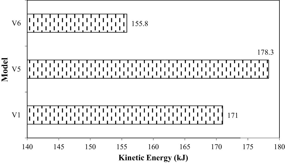
Effect of the amount of fluid on kinetic energy response of the tank.
Figure 12 shows the failure index of three modeling modes V 1, V 5, and V 6. Based on the obtained results, it can be seen that the failure index in the half-full, full, and empty tanks is equal to 0.78, 0.66, and 0.94, respectively. In other words, by changing the condition of the fluid in the tank from full to half-full, the damage index in the tank has increased by 15.4%. Also, by changing the condition of the fluid in the tank from full to empty, the damage index in the tank has increased by 29.8%. In other words, the probability of failure and damage in an empty tank is 29.8 and 17% higher, respectively, compared to a full tank and a half-full tank.

Effect of the amount of fluid on failure index.
3.2 Effect of fluid pressure distribution on behavior of concrete tank
In order to investigate the effect of fluid pressure distribution in the tank, two different modes (uniform and nonuniform distribution) have been considered. In the first case, the fluid pressure distribution is assumed to be rectangular and uniform. In the second case, the fluid pressure distribution is considered triangular and nonuniform. In both cases studied in this section, the cross-section of the tank is circular, the amount of explosive material is 500 kg, the distance of the explosive substance from the tank is 25 m, and the height of the fluid in the tank is 30 m (the tank is full of fluid). Figures 7 and 13 show the stress distribution in V 6 and V 7, respectively. The difference between them is the fluid pressure distribution in the tank. It can be observed that the maximum stress created in model V 6 (uniform fluid pressure) and V 7 are 348 and 916 MPa, respectively. Thus, the nonuniform pressure distribution of the fluid in the tank has caused a 62% increase in the stress distributed in the concrete tank wall.

Von Mises stress distributed in V 7 model.
Figures 10 and 14 show the maximum displacement created in V 6 and V 7, respectively. As it can be seen, the maximum displacement created in model V 6 (uniform distribution of fluid pressure) is equal to 0.73 mm and the maximum displacement created in model V 7 (nonuniform distribution of fluid pressure) is equal to 1.18 mm. Also, it can be seen that the nonuniform distribution of fluid pressure in the tank has caused a 38.1% increase in the maximum displacement in the concrete tank wall.

Displacement in V 7 model.
Figure 15 shows the recorded kinetic energy in two modeling modes of V 6 and V 7. It can be seen that the nonuniform distribution of fluid pressure on the wall of the concrete tank causes a 5% increase in the kinetic energy of the concrete tank. Therefore, based on the obtained results, the kinetic energy in the tank with uniform pressure distribution (V 6) and nonuniform pressure distribution (V 7) are equal to 155.8 and 164 kJ, respectively. Figure 16 shows the failure index of V 6 and V 7 models. Based on the obtained results, the failure index of the full tank with uniform fluid pressure distribution (V 6 model) is equal to 0.66 and the failure index in the nonuniform fluid pressure distribution (V 7 model) is equal to 0.8. Therefore, it can be concluded that with nonuniform distribution of fluid pressure in the tank, the probability of failure and damage in the tank increases by 17.5% compared to the condition of uniform distribution of fluid pressure.

Effect of fluid pressure distribution on kinetic energy response of the tank.

Effect of fluid pressure distribution on failure index response.
Table 4 summarizes the results for concrete tanks with different parameters. As is clear, for the model
Results of the models examined in this study
| Model | Maximum stress (MPa) | Maximum displacement (mm) | Kinetic energy (kJ) | Normalize failure index |
|---|---|---|---|---|
| V 1 | 590 | 7.5 | 171 | 0.78 |
| V 5 | 721 | 10.9 | 178.3 | 0.94 |
| V 6 | 348 | 0.73 | 155.8 | 0.66 |
| V 7 | 916 | 1.18 | 164 | 0.8 |
4 Conclusions
Based on the analysis done in this study, the results can be summarized as follows:
Considering the empty tank, the maximum stress distributed in the tank has increased by 18.1% compared to the base model. Filling the tank with fluid has reduced the maximum stress distributed in the tank wall by 41%.
The nonuniform distribution of fluid pressure in the tank has caused a 35.6% increase in the maximum stress distributed in the tank.
Considering the empty tank, the maximum displacement created in the tank has increased by 31.2% compared to the base model. Filling the tank with fluid has reduced the maximum displacement created in the tank wall by 90%.
The nonuniform distribution of fluid pressure in the tank has reduced the maximum displacement created in the tank by 84.3%.
Considering the empty tank, the kinetic energy created in the tank has increased by 4.1% compared to the base model. Considering that the tank is full of fluid, the kinetic energy generated in the tank wall has decreased by 8.9%.
The nonuniform distribution of fluid pressure in the tank has reduced the kinetic energy created in the tank by 4.1%.
Considering the empty tank, the failure index in the tank has increased by 17% compared to the base model. Considering that the tank is full of fluid, it has caused a 15.4% reduction in the failure index in the tank wall.
The nonuniform distribution of fluid pressure in the tank has caused a 2.5% increase in the failure index in the tank.
-
Funding information: Authors state no funding involved.
-
Author contributions: All authors have accepted responsibility for the entire content of this manuscript and consented to its submission to the journal, reviewed all the results and approved the final version of the manuscript. Majid Alipour: conceptualization, writing – original draft, editing. Mojtaba Hosseini: supervision, data curation, formal analysis. Hamidreza Babaali: editing, supervision, resources, software. Mehdi Raftari: formal analysis, editing. Reza Mahjoub: resources, data curation.
-
Conflict of interest: Authors state no conflict of interest.
-
Data availability statement: The data used to support the findings of this study are available from the corresponding author upon request.
References
[1] Office of Research and Technical Critics of Planning and Budget Organization. Rules and criteria for design and calculation of ground water tanks (Publication No. 123). 2nd edn. Iran: Publication of Planning and Budget Organization; 1995.Search in Google Scholar
[2] Brode HL. Numerical solutions of spherical blast waves. J Appl Phys. 1995;26(6):766–76. 10.1063/1.1722085.Search in Google Scholar
[3] Khanmohammadi M, Akhsvan Hejazi F, Hataminia H. Investigation of the basics of design of concrete water tanks in different code. 8th National Congress on Civil Engineering. Babol; 2014.Search in Google Scholar
[4] Zou D. Theory and technology of rock excavation for civil engineering. Singapore: Springer; 2017. p. 105–70. 10.1007/978-981-10-1989-0.Search in Google Scholar
[5] Chen JK, Kianoush MR. Seismic response of concrete rectangular tanks for liquid containing structures. Can J Civ Eng. 2005;32(4):739–52. 10.1139/l05-023.Search in Google Scholar
[6] Kianoush MR, Chen JK. Effect of vertical acceleration on response of concrete rec tanks. Eng Struct. 2006;28(5):704–15. 10.1016/j.engstruct.2005.09.022.Search in Google Scholar
[7] Ghaemmaghami AR, Kianoush MR. Effect of wall flexibility on dynamic response of concrete rectangular tanks under horizontal and vertical ground motions. ASCE J Struct Eng. 2010;136(4):441–51. 10.1061/(ASCE)ST.1943-541X.0000123.Search in Google Scholar
[8] Safi M, Rasoulpoor S, Mahdavian A. Effect of earthquake frequency content on the dynamic response of rectangular concrete tanks using the combined finite element method and smooth particle hydrodynamics. J Struct Constr Eng. 2019;6(2):87–102. 10.22065/jsce.2018.100667.1348.Search in Google Scholar
[9] Shokoohfar A, Rahai M, Sahrai A. Seismic analysis of prestressed concrete cylindrical tanks. Amirkabir J Civ Eng. 2020;52(6):1577–92. 10.22060/ceej.2019.15441.5935.Search in Google Scholar
[10] Moghadam M, Razavitosee SV, Shahrbanouzadeh M. Dynamic analysis of RC water tanks under explosion by consideration water-structure interaction. Inactive Def Mag. 2021;12(2):53–64. https://dor.isc.ac/dor/20.1001.1.20086849.1400.12.2.5.3.Search in Google Scholar
[11] Mittal V, Chakraborty T, Matsagar V. Dynamic analysis of liquid storage tank under blast using coupled Euler–Lagrange formulation. Thin Walled Struct. 2014;84:91–111. 10.1016/j.tws.2014.06.004.Search in Google Scholar
[12] Shengzhuo L, Wang W, Weidong C, Jingxin M, Yaqin S, Chunlong X. Behaviors of thin-walled cylindrical shell storage tank under blast impacts. Shock Vib. 2019;26:1–21. 10.1155/2019/6515462.Search in Google Scholar
[13] Lotfi R, Mahmoudabadi M, Dehghani E. Investigation of the seismic behavior of the on ground quadruplet elliptical tanks. J Struct Constr Eng. 2021;8(9):184–200. 10.22065/jsce.2020.237737.2181.Search in Google Scholar
[14] Cakir T, Livaoglu R. Fast practical analytical model for analysis of backfill-rectangular tank-fluid interaction systems. Soil Dyn Earthq Eng. 2012;37:24–37. 10.1016/j.soildyn.2012.01.013.Search in Google Scholar
[15] Burkacki D, Robert J. Experimental study on steel tank model using shaking table. Civ Environ Eng Rep. 2014;14(3):37–47. 10.1515/ceer-2014-0024.Search in Google Scholar
[16] Alipour M, Hosseini M, Babaali H, Raftari M, Mahjoub R. Evaluation of the behavior of reinforced concrete above-ground tanks subjected to blast loading. Adv Sci Technol Res J. 2025;19(7):1–24. 10.12913/22998624/202413.Search in Google Scholar
[17] Jin H, Calabrese A, Liu Y. Effects of different damping baffle configurations on the dynamic response of a liquid tank under seismic excitation. Eng Struct. 2021;229:201–11. 10.1016/j.engstruct.2020.111652.Search in Google Scholar
[18] Hu K, Chen G, Zhou C, Reniers G, Qi S, Zhou Z. Dynamic response of a large vertical tank impacted by blast fragments from chemical equipment. Saf Sci. 2020;130:104863. 10.1016/j.ssci.2020.104863.Search in Google Scholar
[19] Yan C, Zhai XM, Wang YH. Numerical study on the dynamic response of a massive liquefied natural gas outer tank under impact loading. J Zhejiang Univ Sci A. 2019;20(11):823–37. 10.1631/jzus.A1900172.Search in Google Scholar
[20] Li J, Huang C, Ma T, Huang X, Li W, Liu M. Numerical investigation of composite laminate subjected to combined loadings with blast and fragments. Compos Struct. 2019;214:335–47. 10.1016/j.compstruct.2019.02.019.Search in Google Scholar
[21] Chen GH, Zhao YX, Xue YZ, Huang K, Zeng T. Numerical investigation on performance of protective layer around large-scale chemical storage tank against impact by projectile. J Loss Prev Process Ind. 2020;69:104351.10.1016/j.jlp.2020.104351Search in Google Scholar
[22] Wu JY, Ji C, Long Y, Song K, Liu Q. Dynamic responses and damage of cylindrical shells under the combined effects of fragments and shock waves. Thin-Walled Struct. 2017;113:94–103. 10.1016/j.tws.2017.01.009.Search in Google Scholar
[23] Zhao Y, Li H, Fu X, Zhang S, Mercan O. Seismic analysis of a large LNG tank considering the effect of liquid volume. Shock Vib. 2020;2020:8889055. 10.1155/2020/8889055.Search in Google Scholar
[24] Sierikova O, Strelnikova E, Degtyarev K. Seismic loads influence treatment on the liquid hydrocarbon storage tanks made of nanocomposite materials. Wseas Trans Appl Theor Mech. 2022;17:62–70. 10.37394/232011.2022.17.9.Search in Google Scholar
[25] Hosseini SEA, Beskhyroun S. Fluid storage tanks: a review on dynamic behaviour modelling, seismic energy-dissipating devices, structural control, and structural health monitoring techniques. Structures. 2023;49:537–56. 10.1016/j.istruc.2023.01.146.Search in Google Scholar
[26] Baumbach MR. Design of metal hollow section tubular columns subjected to transverse blast loads. Thin-Walled Struct. 2013;68:92–105. 10.1016/j.tws.2013.03.001.Search in Google Scholar
© 2025 the author(s), published by De Gruyter
This work is licensed under the Creative Commons Attribution 4.0 International License.
Articles in the same Issue
- Research Articles
- Layerwise generalized formulation solved via a boundary discontinuous method for multilayered structures. Part 1: Plates
- Thermoelastic interactions in functionally graded materials without energy dissipation
- Layerwise generalized formulation solved via boundary discontinuous method for multilayered structures. Part 2: Shells
- Visual scripting approach for structural safety assessment of masonry walls
- Nonlinear analysis of generalized thermoelastic interaction in unbounded thermoelastic media
- Study of heat transfer through functionally graded material fins using analytical and numerical investigations
- Analysis of magneto-aerothermal load effects on variable nonlocal dynamics of functionally graded nanobeams using Bernstein polynomials
- Effective thickness of gallium arsenide on the transverse electric and transverse magnetic modes
- Investigating the behavior of above-ground concrete tanks under the blast load regarding the fluid-structure interaction
- Numerical study on the effect of V-notch on the penetration of grounding incidents in stiffened plates
- Thermo-elastic analysis of curved beam made of functionally graded material with variable parameters
- Effect of curved geometrical aspects of Savonius rotor on turbine performance using factorial design analysis
- A mechanical and microstructural investigation of friction stir processed AZ31B Mg alloy-SiC composites
- Mechanical design of engineered-curved patrol boat hull based on the geometric parameters and hydrodynamic criteria
- Analysis of functionally graded porous plates using an enhanced MITC3+ element with in-plane strain correction
- Review Article
- Technological developments of amphibious aircraft designs: Research milestone and current achievement
- Special Issue: TS-IMSM 2024
- Influence of propeller shaft angles on the speed performance of composite fishing boats
- Design optimization of Bakelite support for LNG ISO tank 40 ft using finite element analysis
- The topology optimization applied to the evaluation study of bracket caliper by using finite element method