
An experimental study on the failure and enhancement mechanism of bolt-strengthening GFRP T-joint subjected to tensile loading
-
Peiyu You


Abstract
The aim of this article is to investigate the failure and enhancement mechanism of bolt-strengthening glass fiber-reinforced polymer (GFRP) T-joints under quasi-static tension. One-step molding technology based on the vacuum-assisted resin infusion process is carried out to fabricate the GFRP T-joints structures. Then, a special fixture and constraint condition are set up to take the quasi-static tensile test with high reliability. Moreover, it is demonstrated that the T-joints structures may decrease their bearing capacity, resulting in interlaminar delamination at the corner region. Further, to strengthen the T-joints, the bolts are employed to effectively prevent the initiation and propagation of interlaminar delamination in the tensile loading. At the same time, as their enhancement and failure mechanisms are revealed deeply, the strengthening method is optimized as well.
1 Introduction
Because of composite structures’ remarkable advantages, such as high stiffness, low weight ratio, and low cost, they are widely utilized in aircraft, manufacturing, and other industries [1,2,3,4]. In various joining methods, the adhesive bonding technique [5,6], low weight and fewer components, bolt joint technique [7,8,9], and higher reliability are the commonly used technologies for composite constructions. Adhesive bonds have increasingly been utilized in industrial applications, for their various superiorities, including higher strength, sealing, and ability to join different materials, over other joining methods such as fastened, welded, and riveted joints [10].
On the other hand, in the field of manufacturing, complex or large structures are always assembled with a significant number of parts, leading to a higher deterioration in productivity and cost. One particular and widespread application of adhesive bonding in aircraft composite structures, the very subject of the present research, is the skin-to-stiffener joint, with stiffeners being adhesively connected to skin sections such as the fuselage or wings [11,12].
However, the T-joints structure has fewer parts. However, due to its complex geometric shape and ply configuration, the T-joints structures are quite different from the panel structures in the failure mechanism. According to the study by Barzegar et al. [13], the failure behavior of T-joints is significantly changed with different fiber volume fractions of adherents, the strength of adherents, and curvature at the corner. Besides, instead of the matrix crush as the rock [14,15,16,17], refs. [18–20] reported that the interlaminar delamination is the principal failure model of a T-joints. As a result, the strength between the layers is one of the most critical properties of the T-joints composite structure. Further, in general, the primary methods to improve the interlaminar strength can be classified into three categories: (i) higher interfacial strength between the fiber and matrix by mechanical or chemical treatments [21,22], (ii) the addition of coupling agent, such as sol/gel [23] as well as multiwalled carbon nanotube [24,25,26] at the fiber–matrix interface, and (iii) mechanical enhancement along the normal direction of the T-joints surface, for instance, Z-pin reinforcement [27,28].
In this study, glass fiber-reinforced polymer (GFRP) T-joints, a typical integrated T-shape composite structure (see Figure 1), consisting of a laminate (named as web) perpendicular to another (named as skin), are manufactured by the novel method based on vacuum-assisted resin infusion (VARI). This type of T-joints is enhanced along the normal vector of the skins with the help of bolts. As their failure mechanism is investigated and revealed by analyzing the response history, including the force–displacement curves and damage evolution of morphology, the strengthen schemes are also optimized further.

The configuration, fabrication progress, and dimension of the T-joints.
2 Experimental methodology
2.1 Materials and fabrication
The conventional VARI process added with two angle iron benches, as described in refs. [29,30], is employed to manufacture the T-joints specimens. The process can be mainly summed as following steps: (1) lay the fiber layers, diversion net, and release cloth on the mold; (2) fix the mold by the bolts and make confined space for the fiber layers with the help of the vacuum bag and sealant; (3) pump the air out by vacuum pump and fill the room with resin via atmospheric pressure; and (4) the curing of the resin at room temperature.
Moreover, both the skin and web laminate have 12 layers of woven glass fiber, 300 g/m2, and a total thickness of 3 mm. Due to its high flowability and curing at room temperature, vinyl epoxy resin is used in the VARI process. In the first step, for clamping, at both sides of all cases, two rectangle blocks are laid on the surface of the benches, and then are released after the curing of T-joints structures. As a result, at both sides of the T-joints, the fixture has less effect on the web layers. Further, the effect of the fixture can be sharply reduced in our experiments. As shown in Figure 1, all T-joints cases are cut into a uniform size of 180 mm length with 25 mm * 2 clamping area, 80 mm height, and 25 mm width.
2.2 Enhancement with bolts and the set-up in the test
As shown in Figure 2, we examine four types of specimens, control group, that is, T-joints without reinforcement (named as T-Raw), skin-bolt-reinforcement group (named as T-S), web-bolt-reinforcement group (named as T-W), and skin-web-bolt-reinforcement group (named as T-SW). Besides, the distance between the bolt hole and the corner is marked at the end of the specimen’s name. For instance, T-S-2 cm means the T-joints with bolt strengthening, 2 cm away from the corner, at the skin laminate. In the experiments, M8 hex socket head bolts with two gaskets at both sides are chosen and applied a uniform torsion of 8 Nm. Finally, all cases are fixed on a T-shape fixture by four M12 bolts. A universal experimental machine is employed to conduct the tensile test with a loading speed of 1 mm/min. At the same time, the failure process of morphology is recorded by a digital video camera.

The setup of tensile loading, varying in the enhancement methods.
3 Results and discussion
3.1 The failure evolution of T-Raw specimens
Three curves of force versus displacement of T-Raw specimens and typical primary failure morphologies are shown in Figure 3. In the tests, first, a short significant linear growth in the force is observed. Then, the force keeps increasing to the ultimate value of about 500 N. During this period, there is no obvious unrecoverable damage, but there is elastic deformation, until the initiation of delamination at the skin interface. At the same time, the force reaches the ultimate value. With the extension of the interlaminar delamination at both skin and web, the degeneration of their carrying capacity is seen.

Force–displacement curves of the T-Raw group.
3.2 The effect of reinforcement location
Typical force–displacement curves, consisting of T-Raw, T-W-2 cm, T-S-2 cm, and T-SW-2 cm, are compared in Figure 4. In addition, their first and second peak-force values, as well as their increased ratio to T-Raw, are listed in Table 1. Compared to T-Raw, T-W-2 cm exhibit a gentle linear increase in the force until reaching the ultimate force of about 458.46 N, which is even smaller than that of T-Raw, 492.3 N. This is because the addition of bolt reinforcement at the web region reduces the strength of web laminate, rather than preventing the extension of interlaminar delamination at the skin. For this season, T-W-2 cm has a similar ultimate force and failure mechanism as the performance of T-Raw. When the bolt reinforcement is applied at the skin laminate 2 cm away from web laminate, named as T-S-2 cm, even though it has a lower first peak force, 446.79 N, than T-Raw and T-W-2 cm, its strength of interlaminar delamination is increased dramatically, resulting in a higher ultimate force, 1032.63 N, and displacement, 23.86 mm. Besides, T-S-2 cm is its first peak force with the initiation of delamination at the corner as T-Raw and T-W-2 cm, see Figure 5. However, after a small slide of tensile force, the enhancing bolts can prevent the interlaminar delamination at the skin region from extending beyond the blot holes. Therefore, with the increase in tensile force, up to the ultimate value of 1032.63 N, there is an extension of interlaminar delamination at the web region, as well as the fiber broken at the blot region, shown in Figure 5.
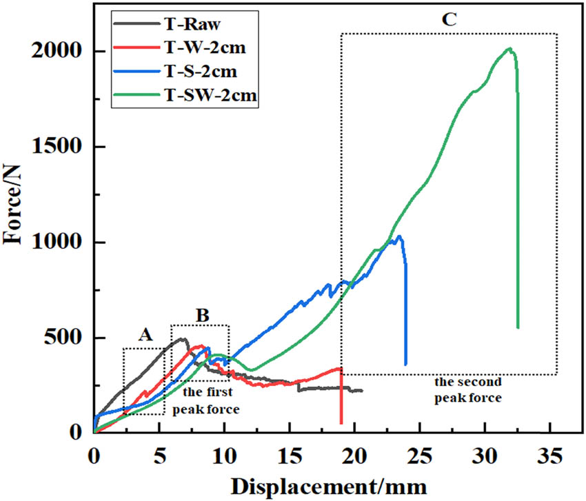
Comparison of various types of T-joints in the force–displacement curves.
Comparison of peak force and their increased percentage
| Case | First peak force (N) | Second peak force (N) | Increased percentage of ultimate force over T-Raw (%) |
|---|---|---|---|
| T-Raw | 492.30 (±83.62) | 0 | 0 |
| T-W-2 cm | 458.46 (±53.69) | 340.20 (±72.63) | −6.87 |
| T-S-2 cm | 446.79 (±36.16) | 1032.63 (±153.62) | 109.75 |
| T-S-3 cm | 457.38 (±49.13) | 1416.93 (±121.62) | 187.82 |
| T-SW-2 cm | 413.60 (±50.33) | 2015.28 (±130.62) | 309.36 |
| T-SW-3 cm | 469.49 (±63.62) | 2332.80 (±174.62) | 373.86 |

Comparison of various kinds of T-joints in the damage morphology at point A, before the first peak force, point B, the first peak force, point C, and the second peak force.
Although, as shown in Figure 4, the bolt strengthened at the web of T-Raw cases, T-W-2 cm, can hardly improve its bearing capacity along the normal vector of skin laminate. As for T-SW-2 cm cases, their ultimate bearing capacity increased dramatically from 2015.28 N to 492.3 N of T-Raw, and even more than double of T-S-2 cm. On the basis of the typical damage evolution of T-SW-2 cm cases shown in Figure 5, they reach the first peak force when the delamination is found at the corner. Then, after a small slide, the tensile force increases significantly again up to the ultimate value until there is fiber broken around the bolt hole at the web laminate. Hence, only if the interlaminar strength of skin laminate is enough, the reinforcement in the web is useful.
3.3 The effect of the reinforcement distance from the corner
To investigate the effect of bolt location on skin laminates, in Figure 6 and Table 1, we experimentally compare the performance of both T-S and T-SW cases with two bolts at the location 2 or 3 cm away from web laminates. On the whole, the delamination initiation at the corner region means that the tensile force reaches its first peak value. Then, when the tensile force reaches the second peak value, that is, the ultimate force, T-S cases exhibit wide interlaminar delamination damage at the web and fiber-broken damage around the bolt holes. Moreover, as listed in Table 1, the cases with bolts at 3 cm can increase the first peak force slightly as well as the ultimate force dramatically.

Comparison of force–displacement of the cases, varying in the strengthened location at the skin laminate.
However, Figure 7 shows the crack evolution of the cases varying in the strengthened location at the skin laminate. Regarding T-SW cases, T-SW-2 cm has less delamination region, resulting in a higher stiffness and easier shear failure mode at the fixture edge. Besides, the T-SW-3 cm cases have a larger curvature to reduce the damage there. Hence, they fail in the fiber broken around the web holes.

Comparison of the damage morphology of the cases, varying in the strengthened location at the skin, at the key points as marked in Figure 6.
4 Conclusions
The GFRP T-joints with/without bolt reinforcement are fabricated via the VARI process, then mechanically characterized by tensile tests. In the experiments, the response histories, including both force–displacement curves and failure evolution, are accurately obtained and analyzed to illuminate their failure and strengthen mechanism. Based on this systematic study, the following conclusions can be drawn:
All the failure of T-joints structures begins with the delamination at the corner region.
The interlaminar delamination at the skin laminate plays an important role in the strength of the T-joints structure because of the prevention of the extension of the delamination that occurred first. Hence, the T-W cases even have a poorer exhibition in strength than T-Raw, and it is a must of enhancing the skin firstly.
Since the reinforcement between the web and skin is set up, the bolt strengthening can work effectively to enhance the tensile force up to 4.74 times greater than that of the control cases, T-Raw.
The blot strengthening of both T-S and T-SW at the skin with a larger distance can be increased due to the presence of large curvature caused by more interlaminar delamination between two bolts at the skin.
The addition of the bolts could lead the region around the hole to break more easily.
Acknowledgments
This work was supported by Foundation of Jiangxi Province of China Educational Committee (grant numbers GJJ211910 and GJJ201907), National “Innovation and Entrepreneurship” Training Program for College Students (2019), the 18th Challenge Cup project, and the 9th Internet + project of the university.
-
Conflict of interest: We declare that we do not have any commercial or associative interest that represents a conflict of interest in connection with the work submitted.
References
[1] Al-Lami A, Hilmer P, Sinapius M. Eco-efficiency assessment of manufacturing carbon fiber reinforced polymers (CFRP) in aerospace industry. Aerosp Sci Technol. 2018;79:669–78.10.1016/j.ast.2018.06.020Suche in Google Scholar
[2] Xu LY, Lu JR, Li KM, Hu J. Experimental study of CFRP laser surface modification and bonding characteristics of CFRP/Al6061 heterogeneous joints. Compos Struct. 2022;283:115030.10.1016/j.compstruct.2021.115030Suche in Google Scholar
[3] Quan D, Wang GL, Zhao GQ, Alderliesten R. On the fracture behaviour of aerospace-grade Polyether-ether-ketone composite-to-aluminium adhesive joints. Compos Commun. 2022;30:101098.10.1016/j.coco.2022.101098Suche in Google Scholar
[4] Hamit A, Sağlam Z, Adin, MŞ. Numerical investigation of fatigue behavior of non-patched and patched aluminum/composite plates. European Mech Sci. 2021;5(4):168–76.10.26701/ems.923798Suche in Google Scholar
[5] Li JL, Mai ZH, Xie JH, Lu ZY. Durability of components of FRP-concrete bonded reinforcement systems exposed to chloride environments. Compos Struct. 2022;279:114697.10.1016/j.compstruct.2021.114697Suche in Google Scholar
[6] Al-Zu’bi M, Fan MZ, Anguilano L. Advances in bonding agents for retrofitting concrete structures with fibre reinforced polymer materials: A review. Constr Build Mater. 2022;330:127115.10.1016/j.conbuildmat.2022.127115Suche in Google Scholar
[7] Yang Y, Zheng W, Liang B, Luo B, Hu WL, Zhang KF, et al. Topography characteristics and formation mechanism of the bolt-hole contact interface during the bolt installation of interference-fit composite structure. Thin Wall Struct. 2022;179:109642.10.1016/j.tws.2022.109642Suche in Google Scholar
[8] Belardi VG, Fanelli P, Vivio F. Analysis of multi-bolt composite joints with a user-defined finite element for the evaluation of load distribution and secondary bending. Composites Part B-Eng. 2021;227:109378.10.1016/j.compositesb.2021.109378Suche in Google Scholar
[9] Adin MŞ, Kılıçkap E. Strength of double-reinforced adhesive joints. Mater Test. 2021;63(2):176–81.10.1515/mt-2020-0024Suche in Google Scholar
[10] Carvalho PMD, Campilho RDSG, Sánchez-Arce IJ, Rocha RJB, Soares ARF. T-joint cohesive zone analysis using dual-adhesives. Procedia Struct Integr. 2022;41:24–35.10.1016/j.prostr.2022.05.005Suche in Google Scholar
[11] Scarselli G, Corcione C, Nicassio F, Maffezzoli A. Adhesive joints with improved mechanical properties for aerospace applications. Int J Adhes Adhes. 2017;75:174–80.10.1016/j.ijadhadh.2017.03.012Suche in Google Scholar
[12] Rao Q, Huang HX, Ouyang ZY, Peng XQ. Synergy effects of multi-walled carbon nanotube and graphene nanoplate filled epoxy adhesive on the shear properties of unidirectional composite bonded joints. Polym Test. 2020;82:106299.10.1016/j.polymertesting.2019.106299Suche in Google Scholar
[13] Barzegar M, Moallem MD, Mokhtari M. Progressive damage analysis of an adhesively bonded composite T-joint under bending, considering micro-scale effects of fiber volume fraction of adherends. Compos Struct. 2021;258:113374.10.1016/j.compstruct.2020.113374Suche in Google Scholar
[14] Yu Y, Zhao DC, Feng GL, Geng DX, Guo HS. Energy evolution and acoustic emission characteristics of uniaxial compression failure of anchored layered sandston. Front Earth Sc-Switz. 2022;10:15.10.3389/feart.2022.841598Suche in Google Scholar
[15] Guo HS, Chen L, Zhu JY, Sun QC, Xiao YX. Application of borehole camera technology in the identification of an instantaneous strain-structural-plane slip rockburst. Bull Eng Geol Environ. 2022;81(5):1–13.10.1007/s10064-022-02658-3Suche in Google Scholar
[16] Zhang HN, Chen CX, Zheng Y, Yu QQ, Zhang W. Centrifuge modeling of layered rock slopes susceptible to block-flexure toppling failure. B Eng Geol Environ. 2020;79(7):3815–31.10.1007/s10064-020-01797-9Suche in Google Scholar
[17] Zhang JH, Li J, Yao YS, Zheng JL, Gu F. Geometric anisotropy modeling and shear behavior evaluation of graded crushed rocks. Constr Build Mater. 2018;183:346–55.10.1016/j.conbuildmat.2018.06.188Suche in Google Scholar
[18] Wan Y, Yao J, Li H, Huang YH, You PY, Xu YC, et al. Experimental studies of low-velocity impact behavior on hybrid metal wire net/woven carbon-fiber reinforced composite laminates. Compos Commun. 2022;32:101185.10.1016/j.coco.2022.101185Suche in Google Scholar
[19] Ekermann T, Hallström S. Pull-off tests of CFRP T-joints with conventional and 3D reinforced fillets. Compos Struct. 2019;223:110893.10.1016/j.compstruct.2019.110893Suche in Google Scholar
[20] Cardoso JV, Gamboa PV, Silva AP. Effect of surface pre-treatment on the behaviour of adhesively-bonded CFRP T-joints. Eng Fail Anal. 2019;104:1188–202.10.1016/j.engfailanal.2019.05.043Suche in Google Scholar
[21] Kim YW. Surface modification of Ti dental implants by grit-blasting and micro-arc oxidation. Mater Manuf Processes. 2010;25(5):307–10.10.1080/10426911003747915Suche in Google Scholar
[22] He PG, Chen K, Yang JL. Surface modifications of Ti alloy with tunable hierarchical structures and chemistry for improved metal–polymer interface used in deepwater composite riser. Appl Surf Sci. 2015;328:614–22.10.1016/j.apsusc.2014.12.081Suche in Google Scholar
[23] Liang CS, Lv ZF, Bo YB, Cui JY, Xu SA. Effect of modified polypropylene on the interfacial bonding of polymer–aluminum laminated films. Mater Design. 2015;81:141–8.10.1016/j.matdes.2015.05.021Suche in Google Scholar
[24] Wang H, Tao J, Jin K. The effect of MWCNTs with different diameters on the interface properties of Ti/CFRP fiber metal laminates. Compos Struct. 2021;266:113818.10.1016/j.compstruct.2021.113818Suche in Google Scholar
[25] Ji CM, Guo JB, Hu JQ, Wang B, Sun YG. Enhanced interfacial adhesion of CF/PEEK-titanium hybrid laminates via introducing micro-nano layers with multi-walled carbon nanotube networks. Compos Sci Technol. 2022;223:109418.10.1016/j.compscitech.2022.109418Suche in Google Scholar
[26] Adin H, Adin MŞ. Effect of particles on tensile and bending properties of jute epoxy composites. Mater Test. 2022;64(3):401–11.10.1515/mt-2021-2038Suche in Google Scholar
[27] Gong Y, Chen XJ, Zou LH, Li XQ, Zhao LB, Zhang JY. Experimental and numerical investigations on the mode I delamination growth behavior of laminated composites with different z-pin fiber reinforcements. Compos Struct. 2022;287:115370.10.1016/j.compstruct.2022.115370Suche in Google Scholar
[28] Zhou JW, Shi YY, Zuo YJ, Shan CW, Gu ZY. Experimental investigation into influences of Z-pin and deltoid on structural properties and damage tolerance of CFRP T-joints. Compos Part B-Eng. 2022;237:109875.10.1016/j.compositesb.2022.109875Suche in Google Scholar
[29] Wan Y, Diao CY, Yang B, Zhang L, Chen SS. GF/epoxy laminates embedded with wire nets: A way to improve the low-velocity impact resistance and energy absorption ability. Compos Struct. 2018;202:818–35.10.1016/j.compstruct.2018.04.041Suche in Google Scholar
[30] Wu Y, Wan Y. The low-velocity impact and compression after impact (CAI) behavior of foam core sandwich panels with shape memory alloy hybrid face-sheets. Sci Eng Compos Mater. 2019;26(1):517–30.10.1515/secm-2019-0034Suche in Google Scholar
© 2022 the author(s), published by De Gruyter
This work is licensed under the Creative Commons Attribution 4.0 International License.
Artikel in diesem Heft
- Regular Articles
- Experimental investigations of a novel pressure microfoam preparation device for dust removal
- Influence of hydrothermal aging on the mechanical performance of foam core sandwich panels subjected to low-velocity impact
- Experimental study on surface wrapping strengthening of EPS particles and its concrete performance
- Modification of mechanical properties of Shanghai clayey soil with expanded polystyrene
- A new EPS beads strengthening technology and its influences on axial compressive properties of concrete
- A novel superabsorbent material based on soybean straw: Synthesis and characterization
- Use of line laser scanning thermography for the defect detection and evaluation of composite material
- Research on back analysis of meso-parameters of hydraulic cemented sand and gravel based on Box-Behnken design response surface
- Hot deformation behavior and microstructure of a 0.5 wt% graphene nanoplatelet reinforced aluminum composite
- Analysis of electromagnetic characteristics of the proposed composite four-rail electromagnetic launcher
- Preparation and characterization of a graphene hybridizing polyurethane damping composite
- Effects of layup parameters and interference value on the performance of CFRP–metal interference fit joints
- Vibration and noise reduction of pipelines using shape memory alloy
- Finite element analysis of behavior and ultimate strength of composite column
- Dynamic response of functionally graded plate under harmonic load with variable gradient parameters
- Deformation behavior of rubber composite based on FEA and experimental verification
- Effects of Z-pin on moisture absorption property and damage mode under flexural load for carbon fiber composite
- Design and testing of a smart rubber stave for marine water-lubricated bearings
- Study of carbon nano-modifier of fly ash in cement concrete mixtures of civil engineering
- Analysis of multiple impact tests’ damage to three-dimensional four-directional braided composites
- Theoretical analysis of aluminum honeycomb sandwich panel supported by reinforced concrete wall under low-speed impact load
- Effects of local fiber discontinuity on the fatigue strength parameter at the fiber inclusion corner in fiber-reinforced composites
- Experimental investigation on compressive properties of three-dimensional five-directional braided composites in hygrothermal environment
- Failure process of steel–polypropylene hybrid fiber-reinforced concrete based on numerical simulations
- A simple method for measuring the monofilament diameter of continuous filament yarn with high bending stiffness via synthetic laser imaging
- Span length effect on flexural properties of composite laminate reinforced with a plain weave carbon fiber fabric in a polymer matrix
- Mechanical properties improving and microstructure characterization of inorganic artificial stone binder
- Effect of thermal treatment process on the structure of C/SiO2 composite aerogels
- Mechanical and corrosion resistance analysis of laser cladding layer
- Wear and corrosion mechanisms of Ni–WC coatings modified with different Y2O3 by laser cladding on AISI 4145H steel
- Damage and failure analysis of composite stiffened panels under low-velocity impact and compression after impact with damp-heat aging
- In-situ CT characterization of 2D woven SiCf/SiC composite loading under compression
- Effect of the manufacturing process on the equivalency qualification of glass fiber reinforced polymer
- Study of concrete properties based on crushed stone sand mixture and fiber of fly ash of thermal power plants
- Establishment of wear mechanism distribution diagram of ZTAp-reinforced iron matrix composites
- Calculation method of elastic modulus for carbon fiber-reinforced plastics considering inhomogeneous interphase
- An experimental study on the failure and enhancement mechanism of bolt-strengthening GFRP T-joint subjected to tensile loading
- The viability of cell that encapsulated in calcium alginate hydrogel beads
- Discussion of ceramic bar reinforced TWIP steel composite structure
- A theoretical framework underlying an accelerated testing method and its application to composites under constant strain rates and fatigue loading
- Theoretical analysis of interfacial design and thermal conductivity in graphite flakes/Al composites with various interfacial coatings
- Multiscale heat conduction and fractal oxidation behaviors of needle-punched carbon/carbon composites
- Numerical simulation of composite grid sandwich structure under low-velocity impact
- Wear properties of Al/TiO2 composites fabricated via combined compo-casting and APB process
- Review Articles
- Application of melanin as biological functional material in composite film field
- Review on research progress of cemented sand and gravel dam
- Communication
- Fabrications and microstructure analysis of cobalt-based coatings by an easy-coating and sintering process
- Letter to the Editor
- Investigation on mechanical and conductive behaviors of nano-graphite-based concrete