Effects of Z-pin on moisture absorption property and damage mode under flexural load for carbon fiber composite
-
Yansheng Fan
 ,
Shaokai Wang
,
Shaokai Wang

Abstract
The effect of carbon fiber Z-pin on carbon fiber composite under moisture condition with and without flexural load was investigated in this work. Moisture absorption property and crack propagation of carbon fiber reinforced epoxy matrix composite and Z-pinned composite were evaluated under moisture only and moisture-coupled load conditions. The moisture property was evaluated by moisture content and microscopic morphology obtained using X-ray micro-computed tomography (X-ray μCT). The microstructures inside composites and Z-pinned composites after moisture conditions and three-point flexural test were detected using X-ray μCT and optical microscope. It illustrates that the moisture content of Z-pinned composites is higher due to the rich-resin pocket brought by the implantation of Z-pin. The cracks are obvious inside Z-pinned composites after moisture-coupled load conditions. It is attributed to the implantation of each pin which is the weak point for stress concentration and crack formation. Failure morphologies on the surface of composites and Z-pinned composites are different under different moisture conditions. Less macro-interlayer cracks are detected on the surface of Z-pinned composites, and plenty of microcracks initiating from pins are observed.
1 Introduction
Carbon fiber composite is widely used in aerospace, marine, and other fields due to its prominent specific strength and stiffness [1,2,3]. Z-Pinning technology is a reliable method to improve delamination resistance of carbon fiber composite subjected to load [4,5,6]. It was reported that Z-pin improved Mode-I and Mode-II delamination resistance of composites [7,8,9], and the improvement effect increased with the decrease of Z-pin diameter [10,11]. And plenty of research proved that the tensile and compression strengths of Z-pinned composites were reduced [12,13,14,15], even after the optimization of relevant parameters [16], such as the diameter of Z-pin [10,17]. However, Z-pinned composites subjected to in-plane load are common in engineering applications. Especially for Z-pinned composites used in marine environments, moisture and in-plane load conditions are critical [18].
Many studies investigated the relationship between in-plane mechanical properties and defects brought by the implantation of Z-pin from experiments and simulations [19,20]. Hoffmann and Scharr reported that the microstructural damage, such as in-plane fiber waviness, played an important role in in-plane mechanical properties [21,22]. They found that Z-pin caused minor in-plane fiber waviness when they were rectangular and aligned lengthwise to the fiber direction. Thus, the retentions of tensile and compression properties were higher in their works. A resin-rich pocket generated after curing of Z-pinned composites would cause decreased fiber volume fraction. Then, the modulus of combined transverse compression and shear load would decrease due to the decrease in fiber volume fraction [23]. In Wang et al.’s work [24], they pointed out that the interface between Z-pin and matrix was susceptible to crack initiation and propagation, which determined flexural performance and delamination resistance. The schematic in Chang study [25] illustrated that the crack initiated from the Z-pin/matrix interface and propagated within resin-rich pocket under transverse tensile stress [26,27]. In addition, the areas around Z-pin were stress concentrated, resulting in fiber fracture or matrix failure from the simulation results [28]. Previous research studies [29] illustrated that the in-plane properties of Z-pinned composites were weakened, mainly attributed to microstructural damages caused by the implantation of Z-pins.
Besides, those microstructural damages affect not only mechanical properties, but also moisture properties of composite [30]. It was reported that the moisture absorption was accelerated by Z-pin, and the moisture content was higher for Z-pinned composites [31]. Microstructure formed by Z-pin, such as the resin-rich pockets, becomes an additional moisture pathway [32]. In addition, the cracks on the interface of pin and laminate also provided a pathway for moisture entrance into composites [33]. Also, the absorbed moisture around Z-pin contributed to softening the interface of pin and laminate, which would lower the bridging traction load [34,35]. Previous research studies demonstrated that the matrix and pin/matrix interface characteristics would be changed under moisture conditions, which in turn affected mechanical properties [36,37]. Furthermore, moisture conditions coupled with load might result in microcrack formation, internal stress changing, and so on [38,39]. It demonstrates that the performance of Z-pinned composites under moisture-coupled load conditions deserves intensive study.
In order to illustrate the effect of in-plane load on Z-pinned composite under moisture conditions, moisture absorption properties and crack characteristics are analyzed in this article. The moisture-only and moisture-coupled flexural load conditions were conducted, respectively. The moisture property was analyzed from moisture content and X-ray micro-computed tomography (X-ray μCT) morphology. The crack initiation from the moisture conditions and development through three-point bending mechanical tests were analyzed. The crack initialization inside composites and Z-pinned composites after moisture conditions were detected using X-ray μCT. Furthermore, the failure morphology of composite and Z-pinned composite was observed using X-ray μCT and optical microscope.
2 Methods
2.1 Materials
Unidirectional prepregs used for manufacturing laminates were composed of carbon fiber and epoxy resin, which had a resin content of 31 wt% and a fiber areal density of 145 g/m2. Carbon fiber tows with the filament number of 240 and 6,000 were prepared for Z-pins with the diameters of 0.1 and 0.5 mm, respectively. Diglycidyl ether Bisphenol-A (DGEBA) epoxy resin was then impregnated into CCF800 carbon fiber tows, and Z-pins were fabricated after the epoxy resin cured at 120°C for 3 h. The fabricated Z-pins were a continuous rod-like component and cut to 20 cm long for easy operation. The diameters of Z-pins with the nominal diameters of 0.1 and 0.5 mm were measured at 106 ± 7 and 505 ± 12 μm in practical. The DGEBA epoxy resin was purchased from China Bluestar Co., Ltd, with the tradename of WSR618. The CCF800 carbon fiber tows were purchased from Weihai TuoZhan Fiber Co., Ltd. The prepregs, with the brand name of UIN10000/9A16, were purchased from Weihai Guangwei Composites Co., Ltd. Release films, breathers, vacuum bag, and sealant tapes for the autoclave process were purchased from Airtech Advanced Materials Group.
2.2 Preparation and characterizations
As for the preparation of Z-pin composite laminate, Z-pins were implanted into the prepregs at the center region of 12.5 mm (width direction) × 10 mm (length direction), as shown in Figure 1a. The prepregs were unidirectionally laid on a heating table at 30 ± 1°C to make them soft. Capillary tubes with an inner diameter of 0.15 and 0.55 mm were implanted into the soften prepregs vertically. Subsequently, the continuous Z-pin was placed into the capillary tubes. Z-pin remained inside composites after the capillary tube was pulled out. Then, the rest of the Z-pins above the top surface of the prepregs was cut off; 2 mm-thickness composite laminates and Z-pin reinforced composite laminates were fabricated using an autoclave process with 120°C curing temperature.
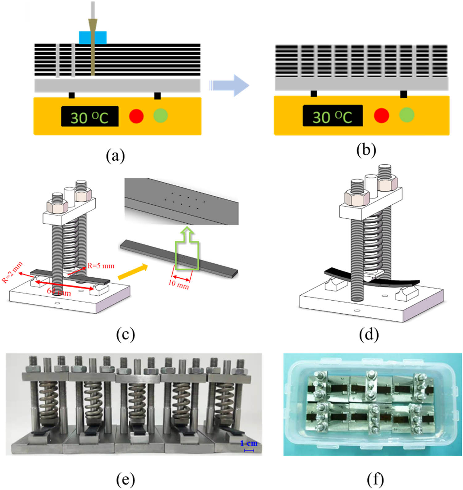
(a–b) Scheme of Z-pin plantation; (c) illustration of self-designed fixture with samples before compressing spring; (d) illustration of self-designed fixture with samples after compressing spring; (e) composite samples under flexural load; and (f) composite samples under moisture coupled with the flexural load.
The dimension of the sample was 80 mm × 12.5 mm × 2 mm. In order to avoid moisture diffusion along the in-plane direction, the samples were sealed with epoxy resin at four edges. The moisture condition was set as 5 times the concentration of simulated seawater at room temperature 23 ± 2°C according to ASTM D1141. Besides, a self-designed fixture was used to implement a three-point flexural load in combination with moisture conditions. The three-point flexural stress applied to the composite sample can be adjusted by controlling the compression degree of a calibrated spring. At least five specimens were used for each case.
Moisture properties of composite and Z-pinned composite were evaluated after moisture-only condition and moisture-coupled flexural load condition. The applied load was 60% of the flexural strength of the composite. The moisture content was calculated according to ASTM D5229, as shown in equation (1), and was determined with three significant digits. Microstructures inside composite and Z-pinned composite after different moisture conditions were detected through X-ray μCT (Nano Voxel TS17139). The resolution for X-ray μCT is 11.86 μm in each direction. Since the ratio of width to thickness is around 6, six specimens can be stacked together for X-ray μCT while ensuring the resolution. The X-ray μCT zone covers the center 12.5 mm (width direction) × 15 mm (length direction) part of composite specimens. The voltage used in the X-ray μCT test is 120 kV, and the current is 80 μA. The exposure time is 0.45 s, and the resolution is 11.8 μA. Figure 2 shows that the slice at different positions can be taken from three directions after X-ray μCT. The three-point flexural test was conducted using a universal testing machine (Instron, 3382), according to ASTM D7264. The macroscopic failure morphology on the lateral surface of the composite and Z-pinned composite was observed after a mechanical test by the optical camera. The internal microstructure after the mechanical test was detected through X-ray μCT.

Illustration of slice selection from X-ray μCT experiment, where the red slice parallels to the fiber direction and vertical to the thickness direction of composite, noted as the first direction; the green slice parallels to the fiber direction and thickness direction of composite, noted as the second direction; the blue slice vertical to the fiber direction and parallels to the thickness direction of composite, noted as the third direction.
3 Results and discussion
3.1 Moisture properties of composite and Z-pin composite after different moisture conditions
Table 1 provides the moisture content of composite and Z-pinned composite after moisture-only condition and moisture coupled with flexural load condition. The moisture content of composites is 0.187 ± 0.010 and 0.211 ± 0.025% after immersion for 7 days with and without flexural load, respectively. For the composites reinforced by 0.5 and 0.1 mm pins, the moisture contents of Z-pinned composites after moisture for 7 days reach 0.232 ± 0.017 and 0.221 ± 0.010%, which are higher than composites without pins. It is noted that the moisture content of Z-pinned composites is higher than that of the composite without Z-pins. In addition, the moisture contents of Z-pinned composites are around 0.200% after moisture coupled with load condition, less than the cases without load. During flexural loading, the part above the middle plane of composites suffers from compressive stress and the part below bears tensile stress. And the area in contact with the loading nose is subjected to compressive stress concentration. It was reported that tensile stress promoted moisture absorption and compressive stress inhibited moisture absorption [40,41]. Therefore, the moisture content in the composite with flexural load is less than that of just moisture condition.
Moisture content of composites under different moisture conditions
| Moisture conditions | Control | 0.5 mm pin | 0.1 mm pin |
|---|---|---|---|
| Moisture for 7 days (%) | 0.211 ± 0.025 | 0.232 ± 0.017 | 0.221 ± 0.010 |
| Moisture coupled with flexural load for 7 days (%) | 0.187 ± 0.010 | 0.209 ± 0.015 | 0.210 ± 0.190 |
Figure 3 depicts microstructures inside composites through thickness direction after different moisture conditions, where the slices are taken through the third direction from X-ray μCT. Morphology inside the composite after moisture for 7 days is shown in Figure 3a, the structure of which is uniform. The morphology after moisture coupled with flexural load is as uniform as that in Figure 3a. Morphologies inside Z-pinned composites after different moisture conditions are presented in Figure 3b–e. As shown, the background outside the composite is black, and the area nearby Z-pin is darker compared with other areas inside the composite. For X-ray μCT technology, the color difference presented in the sample is based on the density difference of material constituents. The smaller the density, the darker the color it presents [42,43]. The background during X-ray μCT is air, which presents as black edge around samples. The density of seawater is around 1.0 g/cm3, which is lower than 1.5 g/cm3 of carbon fiber composites. Therefore, it can be deduced that the dark area at rich-resin pocket around Z-pin in Figure 3b–e is caused by moisture intake. Comparing Figure 3b and c with Figure 3d and e, the moisture absorption is more serious for Z-pinned composite after moisture conditions without load. Therefore, the conclusion can be drawn that the Z-pin implantation contributes to more moisture intake of the composite under moisture conditions. In addition, flexural load helps elevate the moisture intake under moisture conditions.
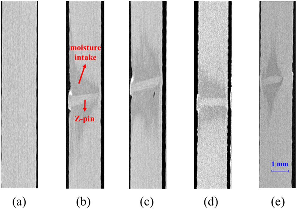
Microscopic morphology through the third direction of (a) composite after moisture for 7 days, (b and c) Z-pinned composite after moisture for 7 days, and (d and e) Z-pinned composite after moisture coupled with flexural load for 7 days.
Similarly, the slice through the second direction presents the morphology inside the sample of the in-plane direction. As depicted in Figure 4a, multiple dark strips appeared inside the Z-pinned composite after moisture for 7 days. And the strips are less significant on Z-pinned composite after moisture-coupled flexural load condition, as shown in Figure 4b. This also illustrates that the flexural load elevates the moisture absorption of Z-pinned composites.

Microscopic morphology through the second direction of Z-pinned composite after (a) moisture for 7 days, and (b) moisture coupled with flexural load for 7 days.
3.2 Crack initiation of composite and Z-pin composite after moisture coupled with flexural load
The morphology characteristic was further analyzed to study the effect of applied flexural load on Z-pinned composites. The pictures were taken at different locations through the second direction of composite from X-ray μCT. As shown in Figure 5a, a crack appears along the interface of the rich-resin pocket brought by Z-pinned implantation. This is because the interface of the rich-resin pocket is a weak point for defect generation. In addition, crack initiates and propagates across the rich-resin pocket as illustrated in Figure 5b–d. Since the pictures were taken at different positions in the thickness direction, it can be deduced that the crack initiation and propagation happened along both in-plane and thickness directions. This implies that the implanted Z-pin is a source of crack generation and then yields crack propagation by the applied mechanical loads. It demonstrates that applying flexural load causes crack inside Z-pinned composite, either at the interface or across the resin pocket zone.
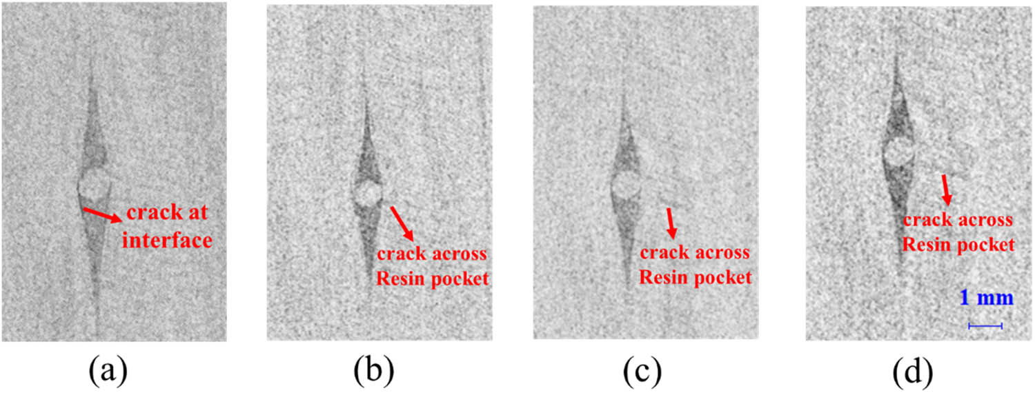
Microscopic morphology at different locations through the second direction of Z-pinned composites after moisture coupled with flexural load for 7 days. (a) Shows crack at interface; (b, c and d) show crack across resin pocket.
Furthermore, the internal microstructure of composite reinforced by 0.1 mm Z-pin was detected. As shown in Figure 6, the Z-pins with a diameter of 0.1 mm are relatively harder to detect than those with 0.5 mm by X-ray μCT. This is because the finer Z-pin causes a smaller rich-resin pocket. There are some relatively long cracks near the 0.1 mm Z-pins and to a certain distance from pins. Compared to the composite reinforced with 0.5 mm pin, the cracks are longer and the amounts of cracks are higher for the composite reinforced with 0.1 mm pin. This is because the implantation of each pin is the weak point for crack and stress concentration [44]. And the number of 0.1 mm pin is higher than that of 0.5 mm pin with the same volume fraction of pin, so more pins result in more weak points for defect generation. And the higher amounts of cracks make the crack connection between adjacent cracks easier, which will contribute to the formation of long cracks. This implies that the diameter and number of Z-pin influence the crack generation inside composite after moisture conditions.
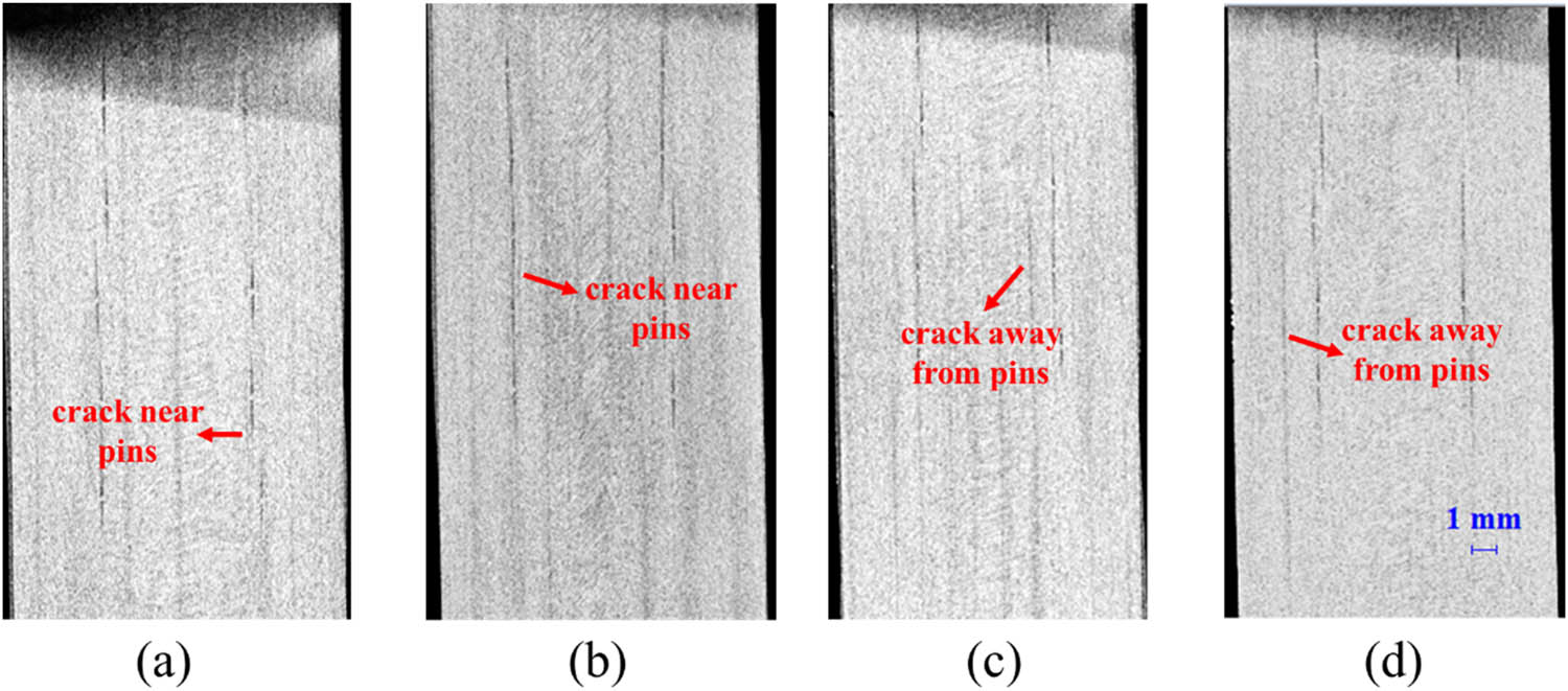
Microscopic morphology at different locations through the second direction of composite reinforced by 0.1 mm Z-pin after moisture coupled with flexural load for 7 days. (a and b) Show crack near pins; (c and d) show crack away from pins.
3.3 Three-point failure morphology of composite and Z-pin composite after moisture coupled with load
Macroscopic morphology after the failure of composite and Z-pin composite after moisture for 7 days is shown in Figure 7. As shown in Figure 7a, the main fracture develops with multiple interlayer cracks on the composite without Z-pin. Those interlayer cracks distribute along the thickness direction. While the cracks on the composite reinforced with 0.5 mm Z-pin after the same moisture condition are not as many as that in Figure 7a, Figure 7b shows the interlayer crack mainly concentrated on the area close to the surface. The moisture might concentrate on the surface of the Z-pinned composite, which is also observed from the result of X-ray μCT, as shown in Figure 3b. All these results conclude that Z-pin can inhibit the development of interlayer cracks by reducing moisture absorption, but the surface moisture is enhanced.

Macroscopic failure process through third direction of (a) composite and (b) Z-pin composite after moisture condition for 7 days.
Macroscopic failure morphology on the lateral surface of composite and Z-pin composite after moisture coupled with flexural load for 7 days were observed, as shown in Figure 8. For the composite after moisture with flexural load, it fails with multiple defects under the three-point flexural test as depicted in Figure 8a. Aside from the main fracture, side fracture, interlayer crack, and secondary fractures are also generated due to failure. The main fracture is caused by the stress concentration at the loading nose during the three-point flexural test. The applied flexural load on moisture conditions might contribute to side fracture and secondary fracture formation. It is because the property of the area subjected to flexural load is weakened, inducing more opportunity for defect generation. In addition, the cracks along the interlayer imply that the interlayer properties of composites are weakened under the moisture condition. As shown in Figure 8b, the failure morphology characteristics are obviously different on Z-pinned composites after the same moisture condition. The main fracture of Z-pinned composite has less width and depth than that of composite without Z-pin. And only similar secondary fractures can be observed on the Z-pinned composite. It can be deduced that Z-pin plays a role in inhibiting more fracture development during loading, i.e., suppressing main fracture and interlayer cracks.
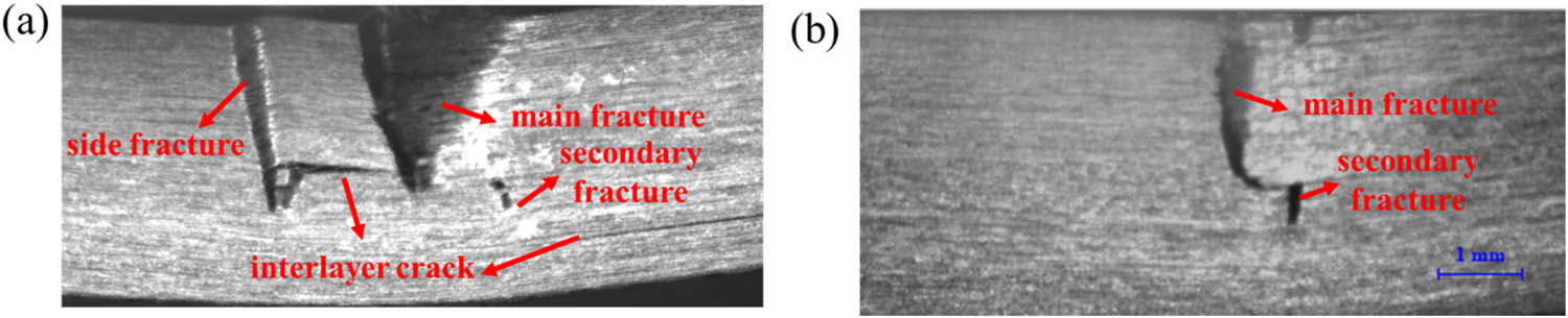
Macroscopic failure process through lateral surface of (a) composite and (b) Z-pin composite under three-point flexural load after 7 day immersion with 60% flexural load.
Further analysis was conducted on the microscopic morphology inside the composite after failure. The morphologies at the center position of composite and Z-pinned composite through the third direction are presented in Figure 9. As shown in Figure 9a, the main fracture bursts out from the loading position inside the composite without Z-pin. Accompanied with that, multiple cracks run across the interlayer direction from the main fracture. Besides, there are some interlayer cracks near the surface not generating from the main fracture. For the Z-pinned composite, the main fracture appears around the loading position which is not that disastrous as in Figure 9a. Multiple cracks are derived around Z-pin, which cross along the interface of Z-pin and laminate and the interface of laminate or run through thickness direction. Meanwhile, cracks not generating from the main fracture are more notable than Figure 9a. It can be deduced that Z-pin suppresses the main fracture to some extent, but derives more microcracks around it. Thus, Z-pin changes the failure morphology obviously.
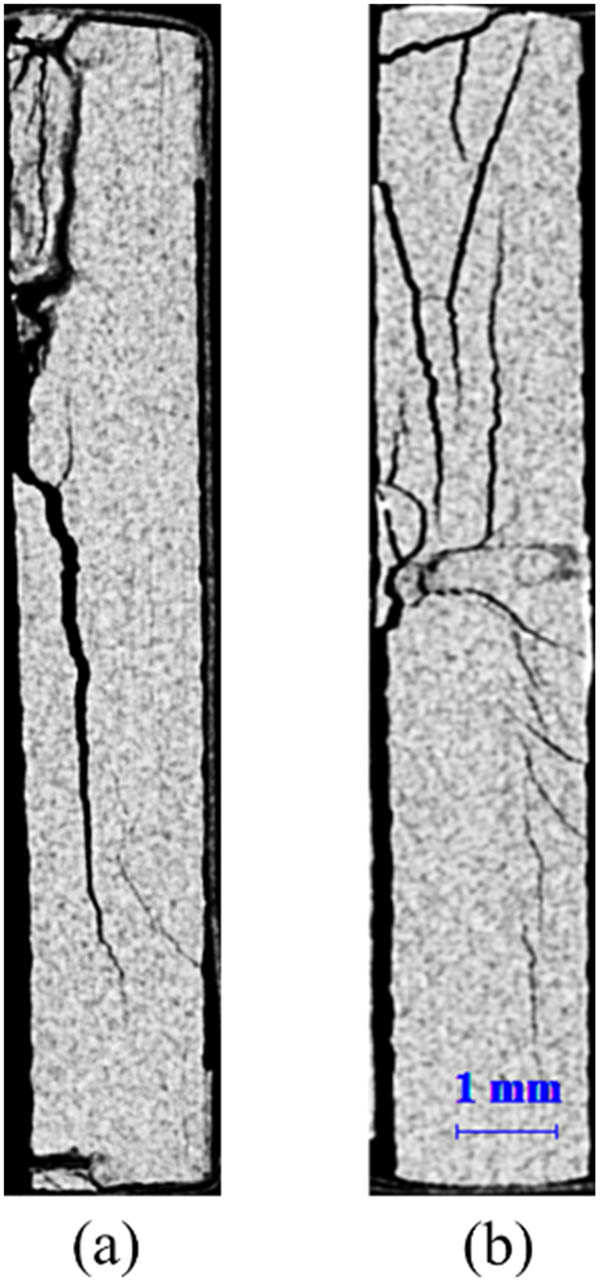
Microscopic morphology through the third direction of (a) composite and (b) Z-pin composite under three-point failure after moisture coupled with flexural load for 7 days.
4 Conclusions
In this article, carbon fiber composite and Z-pinned composite were conditioned for moisture and moisture-coupled flexural load at room temperature. The moisture absorption properties were evaluated from moisture content and microscopic morphology through X-ray μCT examination. The morphological characteristics after moisture conditions and after the mechanical tests were obtained to investigate the impact of moisture conditions on crack initiation and propagation. The following conclusions are drawn.
The composite uptakes more moisture under moisture conditions than that under moisture-coupled flexural load conditions. Z-pinned composite shows the similar characteristic. Combined with microscopic morphology, it demonstrates that Z-pin plays a role in enhancing moisture, which is consistent with the relevant research studies [30,31,32]. Furthermore, it is important to find that the applied flexural load can inhibit moisture absorption of Z-pinned composite.
As for composites reinforced with 0.5 mm Z-pin after moisture and flexural load for 7 days, crack propagation across the resin pocket is observed from the X-ray μCT results. However, no obvious crack is detected inside the composite without Z-pin under the same moisture condition. In addition, there are more and longer cracks inside the 0.1 mm Z-pinned composite. This indicates that the implantation of each pin results in a weak point for crack and stress concentration. These results are in agreement with previous research studies, which indicated that the flexural performance was degraded because the resin pocket zone was susceptible to crack initiation and propagation [23]. The results are verified and developed in more specific and sufficient methods by this work.
Aside from the main fracture, other side fractures and interlayer cracks are detected on three-point flexural failure morphology of composites after moisture conditions. However, only a smaller main fracture is observed on Z-pinned composites, except for a small number of interlayer cracks close to the surface under moisture-only condition. Besides, cracks along the interface of Z-pin and laminate and cracks away from Z-pin are obvious in Z-pinned composites. It demonstrates that Z-pin can inhibit crack generation during mechanical tests, especially for the interlayer cracks, but yields more microcracks around it. These effects brought about by Z-pin should receive careful consideration in composites design for engineering applications. The stress concentration in the resin pocket zone of Z-pinned composite can be reduced by optimizing Z-pin in diameter and number, thus improving the crack initiation and propagation of composite during service. Z-Pin can be partially used to reinforce the areas of composite bearing high flexural load in marine fields, for the benefit of moisture effect counterbalance and crack development inhibition.
Acknowledgment
This work was supported by National Defense Science and Technology Innovation Special Zone. The authors would thank Dr. Zengshan Li for in-situ crack observation system support.
-
Funding information: This work was supported by the Fundamental Research Funds for the Central Universities.
-
Author contributions: Yansheng Fan: methodology, data curation, writing – original draft preparation. Min Li: supervision, conceptualization. Yizhuo Gu: writing – reviewing and edition. Shaokai Wang: validation. Yanjie Wang: formal analysis. All authors read and contributed to the manuscript.
-
Conflict of interest: The authors state no conflict of interest.
-
Data availability statement: The data presented in this study are available on request from the corresponding author.
References
[1] Wu Y, Cheng X, Chen S, Qu B, Wang R, Zhuo D, et al. In situ formation of a carbon nanotube buckypaper for improving the interlaminar properties of carbon fiber composites. Mater Des. 2021;202:109535.10.1016/j.matdes.2021.109535Search in Google Scholar
[2] Afshar A, Liao HT, Chiang FP, Korach CS. Time-dependent changes in mechanical properties of carbon fiber vinyl ester composites exposed to marine environments. Compos Struct. 2016;144(1):80–5.10.1016/j.compstruct.2016.02.053Search in Google Scholar
[3] Adin H, Adin MS. Effect of particles on tensile and bending properties of jute epoxy composites. Mater Test. 2022;64(3):401–11.10.1515/mt-2021-2038Search in Google Scholar
[4] Gnaba I, Legrand X, Wan P, Soulat D. Through-the-thickness reinforcement for composite structures: A review. J Ind Text. 2019;49(1):71–96.10.1177/1528083718772299Search in Google Scholar
[5] Konlan J, Mensah P, Ibekwe S, Crosby K, Li G. Vitrimer based composite laminates with shape memory alloy z-pins for repeated healing of impact induced delamination. Compos Part B Eng. 2022;200:108324.10.1016/j.compositesb.2020.108324Search in Google Scholar
[6] Virakthi A, Kwon S, Lee SW, Robeson ME. Delamination resistance of composite laminated structures reinforced with angled, threaded, and anchored z-pins. J Compos Mater. 2019;53(11):1507–19.10.1177/0021998318805201Search in Google Scholar
[7] Mouritz AP, Koh TM. Re-evaluation of mode I bridging traction modelling for Z-pinned laminates based on experimental analysis. Compos Part B Eng. 2014;56:797–807.10.1016/j.compositesb.2013.09.016Search in Google Scholar
[8] Pingkarawat K, Mouritz AP. Improving the mode I delamination fatigue resistance of composites using z-pins. Compos Sci Technol. 2014;92:70–6.10.1016/j.compscitech.2013.12.009Search in Google Scholar
[9] Pegorin F, Pingkarawat K, Daynes S, Mouritz AP. Mode II interlaminar fatigue properties of z-pinned carbon fibre reinforced epoxy composites. Compos Part A Appl Sci Manuf. 2014;67:8–15.10.1016/j.compositesa.2014.08.008Search in Google Scholar
[10] Fei S, Wang W, Wang H, Yang D, Ding H, Wang H, et al. Effect of 0.11mm Z-pinning on the properties of composite laminates via an ultrasound guided insertion process. Compos Sci Technol. 2021;213:108906.10.1016/j.compscitech.2021.108906Search in Google Scholar
[11] Grassi G, Zhang X. Finite element analyses of mode I interlaminar delamination in Z-fibre reinforced composite laminates. Compos Sci Technol. 2003;63:1815–32.10.1016/S0266-3538(03)00134-9Search in Google Scholar
[12] Tan Y, Li Y, Huan D, Zhang X, Chu Q. Failure analysis and strengthening mechanism of Z-pinned composite T-joints under tensile loading. Sci Eng Compos Mater. 2017;24(5):783–90.10.1515/secm-2015-0388Search in Google Scholar
[13] Mouritz AP. Review of z-pinned composite laminates. Compos Part A Appl Sci Manuf. 2007;38(12):2383–97.10.1016/j.compositesa.2007.08.016Search in Google Scholar
[14] Mouritz AP, Cox BN. A mechanistic interpretation of the comparative in-plane mechanical properties of 3D woven, stitched and pinned composites. Compos Part A Appl Sci Manuf. 2010;41:709–28.10.1016/j.compositesa.2010.02.001Search in Google Scholar
[15] Knopp A, Scharr G. Compression properties of Z-pinned carbon-fibre/epoxy laminates reinforced with circumferentially notched Z-pins. Compos Sci Technol. 2021;201:108486.10.1016/j.compscitech.2020.108486Search in Google Scholar
[16] Li MJ, Chen PH. A numerical study of the influence of Z-pin parameters on the elastic properties of laminates. Polym Polym Compos. 2020;29(9):1390–402.10.1177/0967391120970086Search in Google Scholar
[17] Li M, Che Z, Wang S, Zhou Y, Fu H, Gu Y, et al. Tuning interlaminar fracture toughness of fine z-pin reinforced polymer composite. Mater Des. 2021;212:110293.10.1016/j.matdes.2021.110293Search in Google Scholar
[18] Davim JP. Mechanical and industrial engineering. Heidelberg: Springer; 2022. ISBN: 9783110608281.10.1007/978-3-030-90487-6Search in Google Scholar
[19] Xie SL, Zhang JQ, Guo ZS, Hu HJ. Prediction of compressive strength of z-pinned unidirectional composite laminates. J Compos Mater. 2012;46(4):383–90.10.1177/0021998311419875Search in Google Scholar
[20] Li CH, Guo W, Wu Z. Tensile strength of Z-pinned laminates in RTD and hot-wet environment. Sci Eng Compos Mater. 2017;24:101–9.10.1515/secm-2014-0352Search in Google Scholar
[21] Hoffmann J, Scharr G. Mechanical properties of composite laminates reinforced with rectangular Z-pins in monotonic and cyclic tension. Compos Part A Appl Sci Manuf. 2018;109:163–70.10.1016/j.compositesa.2018.03.004Search in Google Scholar
[22] Hoffmann J, Scharr G. Compression properties of composite laminates reinforced with rectangular Z-pins. Compos Sci Technol. 2018;167:463–9.10.1016/j.compscitech.2018.08.042Search in Google Scholar
[23] Cui H, Melro AR, Yasaee M. Inter-fibre failure of through-thickness reinforced laminates in combined transverse compression and shear load. Compos Sci Technol. 2018;165:48–57.10.1016/j.compscitech.2018.06.011Search in Google Scholar
[24] Wang S, Zhang YH, Sun PB, Cui YH, Wu GH. Microstructure and flexural properties of z-pinned carbon fiber-reinforced aluminum matrix composite. Materials. 2019l;12(1):174.10.3390/ma12010174Search in Google Scholar PubMed PubMed Central
[25] Chang P, Mouritz A, Cox B. Properties and failure mechanisms of z-pinned laminates in monotonic and cyclic tension. Compos Part A Appl Sci Manuf. 2006;37(10):1501–13.10.1016/j.compositesa.2005.11.013Search in Google Scholar
[26] Mouritz A, Chang P. Tension fatigue of fibre-dominated and matrix-dominated laminates reinforced with Z-pins. Int J Fatigue. 2010;32(4):650–8.10.1016/j.ijfatigue.2009.09.001Search in Google Scholar
[27] Gong B, Ouyang W, Nartey M, Wang H, Potter KD, Peng HX. Minimizing the in-plane damage of Z-pinned composite laminates via a pre-hole pin insertion process. Compos Sci Technol. 2020;200:08413.10.1016/j.compscitech.2020.108413Search in Google Scholar
[28] Wang WW, Wang H, Dong HY, Ke YL. Micro-damage initiation evaluation of z-pinned laminates based on a new three-dimension RVE model. Compos Struct. 2021;263:113725.10.1016/j.compstruct.2021.113725Search in Google Scholar
[29] Davim JP. Modern mechanical engineering. Berlin, Germany:Springer; 2014. ISBN: 978-3-642-45176-8.10.1007/978-3-642-45176-8Search in Google Scholar
[30] Davim JP. Green composites. Berlin, Germany: DE Gruyter; 2017. ISBN: 9783110435788.10.1515/9783110435788Search in Google Scholar
[31] Mouritz AP. Delamination properties of z-pinned composites in hot–wet environment. Compos Part A Appl Sci Manuf. 2013;52:134–42.10.1016/j.compositesa.2013.03.010Search in Google Scholar
[32] Ma D, Li Y, Sun T, Fan L, Wang Pand Xiao J. Tensile properties of z-pins reinforced laminates. Polym Polym Compos. 2011;19:4–5.Search in Google Scholar
[33] Mouritz AP. Environmental durability of Z-pinned carbon fibre–epoxy laminate exposed to water. Compos Sci Technol. 2012;72(13):1568–74.10.1016/j.compscitech.2012.06.006Search in Google Scholar
[34] Mouritz AP. Structural properties of Z-pinned carbon-epoxy T-joints in hot-wet environment. J Compos Mater. 2014;48(23):2905–14.10.1177/0021998313503390Search in Google Scholar
[35] Salamt-Talab M, Delzendehrooy F, Akhavan-Safar A, Safari M, Bahrami-Manesh H, da Silva LFM. Environmental effects on mode II fracture toughness of unidirectional E-glass/vinyl ester laminated composites. Sci Eng Compos Mater. 2021;28:382–93.10.1515/secm-2021-0028Search in Google Scholar
[36] Knopp A, Düsterhöft C, ReichelM, Scharr G. Flexural properties of z-pinned composite laminates in seawater environment. J Mater Sci. 2014;49(24):8343–54.10.1007/s10853-014-8543-2Search in Google Scholar
[37] Lei YP, Luo L, Kang ZH. Modified Halpin–Tsai equation for predicting interfacial effect in water diffusion process. Sci Eng Compos Mater. 2021;28:180–9.10.1515/secm-2021-0017Search in Google Scholar
[38] Abdel-Magid B, Ziaee S, Gass K, Schneider M. The combined effects of load, moisture and temperature on the properties of E-glass/epoxy composites. Compos Struct. 2005;7:320–6.10.1016/j.compstruct.2005.09.022Search in Google Scholar
[39] Humeau C, Davies P, Jacquemin F. An experimental study of water diffusion in carbon/epoxy composites under static tensile stress. Compos Part A Appl Sci Manuf. 2018;107:94–104.10.1016/j.compositesa.2017.12.016Search in Google Scholar
[40] Neumann S, Marom G. Stress dependence of the coefficient of moisture diffusion in composite materials. Polym Compos. 1985;6:9–12.10.1002/pc.750060103Search in Google Scholar
[41] Gueribiz D, Jacquemin F, Fréour S. A moisture diffusion coupled model for composite materials. Eur J Mech A/Solids. 2013;42:81–9.10.1016/j.euromechsol.2013.04.008Search in Google Scholar
[42] Zhang H, Li C, Dai W, Liu Y, Tian S, Huang W, et al. Static compression testing CFRP single-lap composited joints using X-ray μCT. Compos Struct. 2019;234:111667.10.1016/j.compstruct.2019.111667Search in Google Scholar
[43] Tretiak I, Smith RA. A parametric study of segmentation thresholds for X-ray μCT porosity characterisation in composite materials. Compos Part A Appl Sci Manuf. 2019;123:10–24.10.1016/j.compositesa.2019.04.029Search in Google Scholar
[44] Chang P, Mouritz AP, Cox BN. Flexural properties of z-pinned laminates. Compos Part A Appl Sci Manuf. 2007;38(32):244–51.10.1016/j.compositesa.2006.05.004Search in Google Scholar
© 2022 Yansheng Fan et al., published by De Gruyter
This work is licensed under the Creative Commons Attribution 4.0 International License.
Articles in the same Issue
- Regular Articles
- Experimental investigations of a novel pressure microfoam preparation device for dust removal
- Influence of hydrothermal aging on the mechanical performance of foam core sandwich panels subjected to low-velocity impact
- Experimental study on surface wrapping strengthening of EPS particles and its concrete performance
- Modification of mechanical properties of Shanghai clayey soil with expanded polystyrene
- A new EPS beads strengthening technology and its influences on axial compressive properties of concrete
- A novel superabsorbent material based on soybean straw: Synthesis and characterization
- Use of line laser scanning thermography for the defect detection and evaluation of composite material
- Research on back analysis of meso-parameters of hydraulic cemented sand and gravel based on Box-Behnken design response surface
- Hot deformation behavior and microstructure of a 0.5 wt% graphene nanoplatelet reinforced aluminum composite
- Analysis of electromagnetic characteristics of the proposed composite four-rail electromagnetic launcher
- Preparation and characterization of a graphene hybridizing polyurethane damping composite
- Effects of layup parameters and interference value on the performance of CFRP–metal interference fit joints
- Vibration and noise reduction of pipelines using shape memory alloy
- Finite element analysis of behavior and ultimate strength of composite column
- Dynamic response of functionally graded plate under harmonic load with variable gradient parameters
- Deformation behavior of rubber composite based on FEA and experimental verification
- Effects of Z-pin on moisture absorption property and damage mode under flexural load for carbon fiber composite
- Design and testing of a smart rubber stave for marine water-lubricated bearings
- Study of carbon nano-modifier of fly ash in cement concrete mixtures of civil engineering
- Analysis of multiple impact tests’ damage to three-dimensional four-directional braided composites
- Theoretical analysis of aluminum honeycomb sandwich panel supported by reinforced concrete wall under low-speed impact load
- Effects of local fiber discontinuity on the fatigue strength parameter at the fiber inclusion corner in fiber-reinforced composites
- Experimental investigation on compressive properties of three-dimensional five-directional braided composites in hygrothermal environment
- Failure process of steel–polypropylene hybrid fiber-reinforced concrete based on numerical simulations
- A simple method for measuring the monofilament diameter of continuous filament yarn with high bending stiffness via synthetic laser imaging
- Span length effect on flexural properties of composite laminate reinforced with a plain weave carbon fiber fabric in a polymer matrix
- Mechanical properties improving and microstructure characterization of inorganic artificial stone binder
- Effect of thermal treatment process on the structure of C/SiO2 composite aerogels
- Mechanical and corrosion resistance analysis of laser cladding layer
- Wear and corrosion mechanisms of Ni–WC coatings modified with different Y2O3 by laser cladding on AISI 4145H steel
- Damage and failure analysis of composite stiffened panels under low-velocity impact and compression after impact with damp-heat aging
- In-situ CT characterization of 2D woven SiCf/SiC composite loading under compression
- Effect of the manufacturing process on the equivalency qualification of glass fiber reinforced polymer
- Study of concrete properties based on crushed stone sand mixture and fiber of fly ash of thermal power plants
- Establishment of wear mechanism distribution diagram of ZTAp-reinforced iron matrix composites
- Calculation method of elastic modulus for carbon fiber-reinforced plastics considering inhomogeneous interphase
- An experimental study on the failure and enhancement mechanism of bolt-strengthening GFRP T-joint subjected to tensile loading
- The viability of cell that encapsulated in calcium alginate hydrogel beads
- Discussion of ceramic bar reinforced TWIP steel composite structure
- A theoretical framework underlying an accelerated testing method and its application to composites under constant strain rates and fatigue loading
- Theoretical analysis of interfacial design and thermal conductivity in graphite flakes/Al composites with various interfacial coatings
- Multiscale heat conduction and fractal oxidation behaviors of needle-punched carbon/carbon composites
- Numerical simulation of composite grid sandwich structure under low-velocity impact
- Wear properties of Al/TiO2 composites fabricated via combined compo-casting and APB process
- Review Articles
- Application of melanin as biological functional material in composite film field
- Review on research progress of cemented sand and gravel dam
- Communication
- Fabrications and microstructure analysis of cobalt-based coatings by an easy-coating and sintering process
- Letter to the Editor
- Investigation on mechanical and conductive behaviors of nano-graphite-based concrete