Comparison between cement and chemically improved sandy soil by column models using low-pressure injection laboratory setup
-
Mohammed S. Mohammed
 ,
Samir H. Hussein
,
Samir H. Hussein

Abstract
The jet grouting method for soil improvement represents an innovative geotechnical alternative for problematic soils when the classic foundations’ designs cannot be appropriate, sustainable solutions for these soils. This study’s methodology was based on producing column models using a low-pressure injection laboratory setup designed and locally manufactured to approximate the field-equipment operation. The setup design was inspired by the works of previous researchers, where its functioning was validated by systematically performing unconfined compression tests (UCTs). Two soil improvement techniques were investigated, one by low-pressure injection of a mixture of water and ordinary Portland cement (OPC) with 0.8, 1, and 1.3 W/C ratios. The other type uses silica fume (SF) as a chemical additive with 10% of the cement weight added to the water and cement mix with 1, 1.3, and 1.6 W/C ratios. The study revealed that the UCT results of SF column model samples were higher than those of OPC with an equal W/C ratio. For each binder type, the UCT sample results increase with a decrease in the W/C ratio.
1 Introduction
Ground improvement or ground enhancement denotes the modification techniques for the soil engineering characteristics executed in a field where the soil in its natural conditions does not have suitable characteristics for the planned civil engineering projects [1]. Essential research works into developing and improving ground modification methods have been carried out in the last few years. Thus, new types of machinery, materials, and applications are regularly suggested on the market and offered to practitioners as an appropriate alternative [2].
The ground improvement involves any process executed to enhance the shear strength, reduce the compressibility and permeability, or modify the soil’s geotechnical characteristics to be more suitable for expected engineering applications. Many techniques have been developed for ground modification from the ground surface down to depths of 20 m or more, depending on the field situation. The improvement may be made by (excavating the poor soil and replacing it with desired soil properties down to 3 m depth in the absence of the water table) compaction, drainage, grouting, preloading, reinforcement, electrical, chemical, or thermal methods. Among the various soil stabilization procedures, the most suitable one is selected depending on the type of soil available, time, cost, etc. [3].
This experimental study was performed by utilizing a low-pressure injection laboratory setup designed and locally manufactured with almost the same performance as the field equipment operation but with a reduced footprint and cost. The improved soil was loose fine sand with a 20% relative density from Karbala province. For comparison between cement and chemical improvement techniques, this laboratory setup injected two binders, one by using OPC with 0.8, 1, and 1.3 W/C ratios and the other by using SF with 10% of the cement weight as a chemical additive to the water and cement mixture with 1, 1.3, and 1.6 W/C ratios.
The design of the laboratory setup was inspired by and based upon the works of both Nikbakhtan [4] and Khalili et al. [5]. Its operation was verified by methodically performing UCTs program. In addition, the setup performance was validated regarding the homogeneity and reproducibility of the low-pressure injected model column samples (performing many laboratory-injection trials to determine the suitable ranges of the setup operational parameters like injection pressure (kPa), flow rate (l/min), diameter (mm), number of nozzles, lifting/penetrating speed (cm/min), and rotating speed (rpm) of the drilling and injection rod).
Grouted cement is an appropriate method to enhance the geotechnical characteristics of the soil. Unfortunately, field conditions do not usually provide a considerable study of the injected soil’s behavior. Therefore, the soil injection technique has been reproduced in the laboratory. In many instances, the laboratory injection test’s key objective is to evaluate grout injectability in a particular soil. Some applicable injectability procedures have therefore been suggested. Laboratory injection tests are intended to comprehend the physical or chemical mechanisms that occur while the injected binder permeates the soil. Another purpose of laboratory injection setup is to prepare consistent homogenous model of the injected samples for modeling geotechnical field cases to be improved by grouted columns technique [6].
2 Grouting techniques and material properties
2.1 Jet grouting
Jet grouting or high-pressure grouting can be utilized in just about all soil types, from gravels to clays (irrespective of the size of particles, pore size, or void ratio), to produce different forms (stiff, impermeable poles, sheets, or wings). Cement grouting uses a high-pressure jet (a minimum of 30 MPa jetted out of the nozzles at excessive-rotation speed) to destroy the subsoil structure to mix and partly substitute it with the grout [2]. The additive contains a mix of cement and water in different ratios. The water–cement mix achieves a significant amount of kinetic energy or velocity while passing through the nozzles on the cement grouting equipment, which creates a soilcrete body with strength properties independent of the initial soil texture [7].
Grouting has been widely used to achieve various purposes, including enhancing the bearing capacity of foundations, increasing the stability of slopes and sub-ground infrastructures, and mitigating the liquefaction phenomenon [8]. The essential benefit of grouting is that it is straightforward, profitable, simple equipment, and eco-friendly. Grouting is categorized generally as cement or jet grouting and chemical grouting. According to previous practical studies, jet grouting has achieved many practical advances concerning the size of jet grouting columns and their geotechnical properties [9].
Njock et al. studied the advanced jet grouting manufacturing approaches to remove the troubles that come with cement grouting, such as inconsistency of the grouted columns and spoil grouting encountered in cement grout applied on the sand. It was revealed that the compressive strength and the continuity properties could be enhanced. Using the cement grouting method, the geotechnical properties of underground layers are improved, resulting in an increase in the soil elasticity modulus and stiffness. Cement grout is multipurpose because it can be executed in vertical, tilted, or even horizontal directions [10].
Cement grouting columns are installed mainly to enhance bearing capacity and reduce settlement of footings on soft soils under static loading. However, cement grouted columns will similarly alternate soft soil deposits’ responses to seismic excitation [11]. It must also be noted that cement-grouted columns can be utilized as a mitigation technique for soils that have the potential to liquefy under seismic loading [12]. Shen et al. established an empirical formulation to state the size of the obtained column by grouted cement practice as a function of grouted pressure, nozzle size, a withdrawal rate of grouting rod, type of subsoil, and soil undrained shear strength [13].
The maximum influencing factor affecting the success of grouting applications within the subsoil is the characteristics of grouted materials or binder materials. OPC is used as a grouted substance contracted by medium- to fine-grained soils because of its grain size (fineness) [14]. For the grouting performed in medium- to fine-grained soil types, fine-grained cement is most required. Grouting using fine-grained cement has advantages over OPC concerning the rheological characteristics. Grouting with fine-grained cement shows more stable properties [15].
The results of cement grouting applications on sand depend on the sand’s relative density and particle size, the type of cement used, the (W/C) ratio of the grouted mix, and the preparation procedure of grouting [16]. The presence of relatively large gaps between the minimum and maximum particle size of soil causes a substantial rise in penetrability. On the contrary, the soil with a homogeneous particle-sized distribution impedes the permeation of binder particles through soil pores, resulting in inaccessibility to the required spaces [17]. In a field study (Al-Kinani and Mahmood, 2020) in Iraq to improve clayey soil layers using the cement grouting technique, it was revealed that the cement grout produced a rise in UCS of the natural soil (which ranged from 30 to 40 kPa) to about 4 MPa after improving [18].
2.2 Chemical grouting
Chemical grouting is an active technique to enhance soil characteristics by mixing additives into the soil. Generally, the additives are lime, cement, fly ash, SF, and bituminous substances. These additives improve the soil characteristics. Typically, the two main reactions for chemical soil improvement are the cementation and cation exchange reactions. The typical chemical agents for cementation are lime, PC, bituminous emulsion, fly ash, and sodium silicate polyacrylamides [19]. Kazemian and Huat (2010) remarked that several grouted chemicals are formed from the mixture of sodium silicate and a reagent to produce a gel. The chosen reagent type and its ratio can regulate the gel time, the initial viscosity, and the strength order of grouted soil [20].
Grouted chemicals are injected into pores as a solution as opposed to cementitious grouting, which suspends the elements in a fluid medium. The dissimilarity between grouted chemicals and grouted cement is that grouted chemicals can seal the smaller pores of soil grains up to 10–15 nm. It has better infiltration capability than grouted cement [21]. Grouted chemicals can be categorized into single-step and two-step procedures. In the one-step procedure, all the constituents are premixed earlier to grouting, proportioning the constituents so that reaction occurs within the soil. In the two-step process, the initial chemical is grouted into soil particles, followed by the second chemical constituent for reaction with the first field injected material for soil stabilizing [22].
Grouted chemicals are used in the pre-treatment of relatively coarse soils for tunnel construction or sealing off water from seeping into deep excavations or tunnels. Applications of chemical grouting for expanding the serviceable life of construction activities are improving collapsible soils, reducing the soil’s liquefaction potential, reducing secondary compression, and reducing soil coefficient of conductivity by decreasing water seeping under footings. The benefits of grouting chemicals are the capability of stabilizing current main roads without transportation disruption, improving the soil with a low conductivity coefficient (about 10 × 10−5 cm/s) up to a practical depth of 30 m, and producing long-lasting constructed projects. Defects are extended periods for project design, constructing, observing periods, extended setting periods, somewhat above average budgets, some chemicals with high toxicity, and disintegration of grouted chemicals over time, thus decreasing their effectiveness [23].
2.3 SF
SF is defined by the American Concrete Institute as “very fine non-crystalline silica produced in electric arc furnaces as a by-product in the production of alloy silicon or elemental silicon” [24]. The gases produced through the furnace operation are a fine powder known as silica fume that is condensed in the bag house through the filtration system to be packed for commercial usage. SF consists of very fine spherical particles less than 1 μm in diameter [25]. SF is a very reactive pozzolanic material in concrete for it contains a very high amount of amorphous silicon dioxide.
SF not only fills the pores between the particles but also improves the bonds between the soil and injection mixtures owing to its microscopic grain structure [26]. As the PC in concrete begins to react chemically, it releases calcium hydroxide. The silica fume reacts with this calcium hydroxide to form additional binder material called calcium silicate hydrate, which is very similar to the calcium silicate hydrate formed from the PC [27].
Wilson et al. stated that SF contained in concrete samples raises the stiffness and reduces the conductivity coefficient. According to scanned electron microscope image investigation, nanoscale SF is not just a filling substance but also improves consistent hydration distributions. In addition, they observed that SF is an energizer to improve the micro-patterned cement paste [28]. Zhang and Li (2013) stated that adding SF to concrete and fly ash mix has significantly enhanced its durability and workability (regarding carbonation resistance and freeze-thaw resistance, waterproofness, and dry shrinkage property). Also, it was revealed that the increase in the SF% resulted in a slight increase in the samples’ relative dynamic elastic modulus, and a decrease in the length of water permeability and the carbonation depth [29].
3 Manufacturing low-pressure injection laboratory setup
The laboratory low-pressure injection setup (as shown in Figure 1), which was manufactured by the study researchers in the local industrial markets, consists of the following parts:
A steel frame consists of hollow square steel tube sections welded together to hold the setup parts and supported by heavy-duty steel swivel caster wheels.
A mixing tank with a 100 L capacity (Plate 1) is supplied with a mixing motor connected by a mixing rod ending with a blending blade. The mixing motor of 0.5 HP is controlled by three-phase frequency converters to control the mixing speed rotation of the mixing rod. A ¾ inch diameter galvanized pipe connects the bottom of the mixing tank to the injection pump that connects the circulating pipe.
A drainage valve plug for washing, cleaning, and draining the injecting tank is supplied to the bottom of the mixing tank.
The used injection pump is an open impeller type, usually used for thick fluid pumping (like the injection fluid) with 1 HP and 3,000 rpm connected to the mixing tank from one side and the soil-injecting system from the other.
The pipe system connected with the injecting pump branched into three branches. The main branch connects the bottom of the mixing tank to the injecting pump (controlled by a gate valve kit and a diaphragm pressure gauge for controlling the fluid injection pressure that ranges from 15 to 25 kPa depending on soil injection depth and the required column models diameter). The second branch circulates the surplus grouting fluid to the mixing fluid tank. Moreover, the third part joins a reinforced plastic hose to transmit the injection fluid from the injection pipe (main branch) to the injection system.
The lifting and lowering of the platform injection system consist of:
A 3-phase electric motor is coupled to a gearbox (Figure 1). The gearbox is connected to a 30 mm diameter screw shaft with square threads supplied with a large net. This net is welded to an inner box that is slipped into an external box fixed to the frame setup. According to platform motor rotation speed and its gearbox reducing speed, the internal steel box (supporting the injection system) slipped (at 0.2 m/min) up and down into an external steel box within a vertically ranged distance limited and controlled by electric limit switches which were fixed to the setup frame.
A three-phase variable speed geared motor with 1 HP will rotate the injection rod clockwise and counterclockwise (Plate 3).
The three-phase electric control board consists of accessories like electric contactors, overloads, selector switches, phase failure device, emergency switch, pushbuttons, and all other fittings to control and operate the motors and the grouting pump.
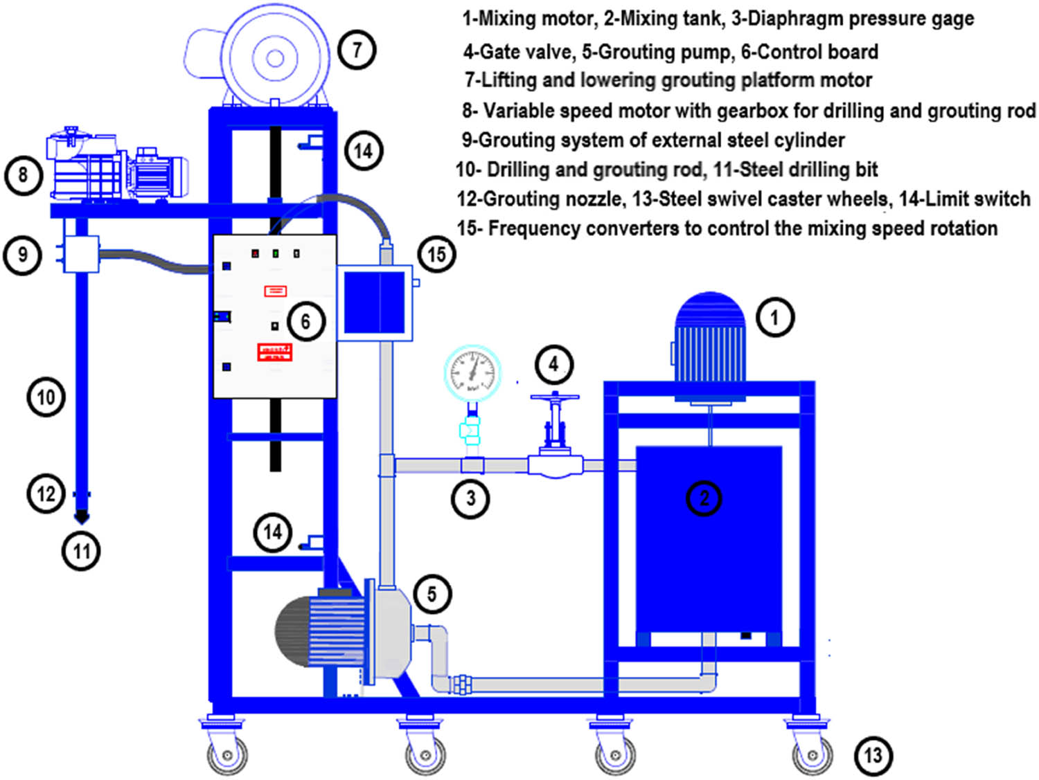
Schematic diagram of the low-pressure injection laboratory setup.
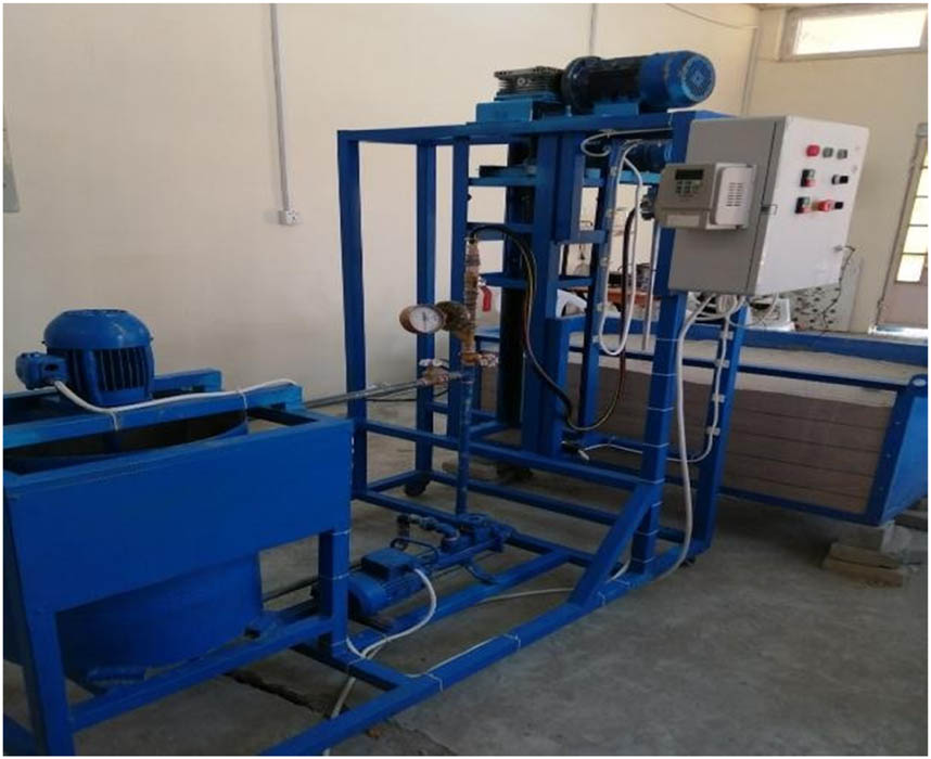
Side view of the low-pressure injection laboratory setup.
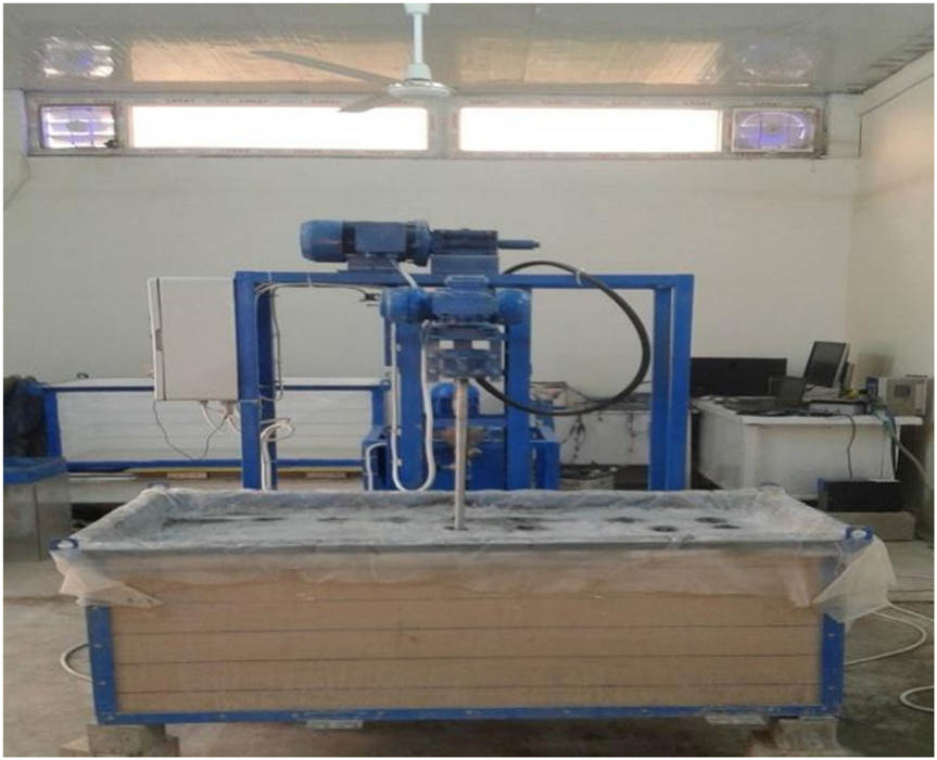
Front view of the low-pressure injection laboratory setup.
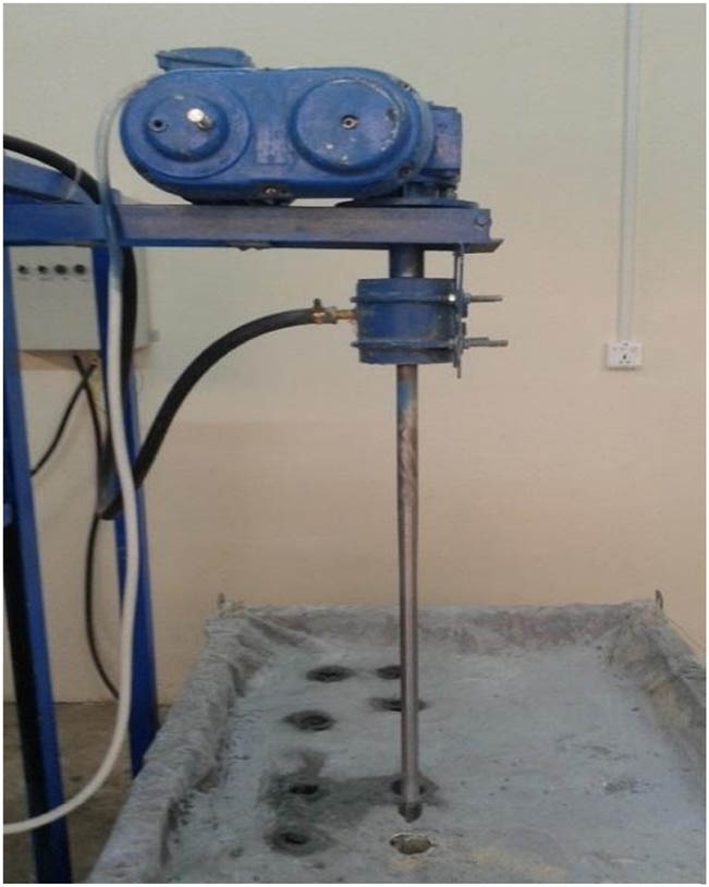
Rotating motor and grouting system.
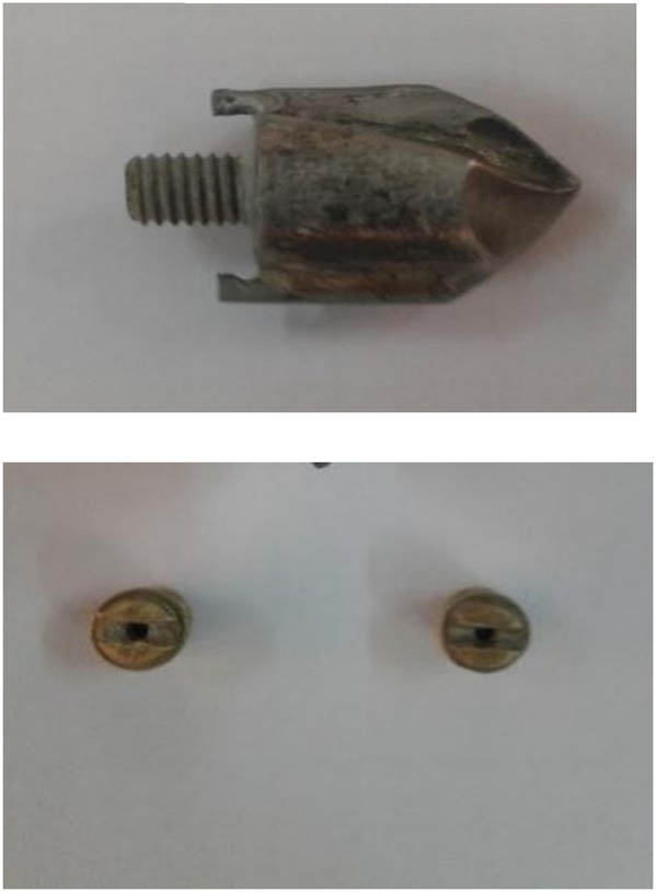
Steel drill kit and the nozzles.
4 Preparing the soil testing box
The tested soil in this study is poorly graded sand passing through sieve #10 (2 mm opening) size, and its geotechnical characteristics are listed in Table 1. The preparation of the soil testing box requires the following steps:
The sand in the soil box is spread in layers with 10 cm height for each layer using the raining (air pluviation) technique (shown in Plates 5 and 6). This technique is used to prepare uniform sand layers for testing large-sized specimens based on laboratory maximum and minimum relative density values (or dry densities) by referring to Eq. (1).
(1)In this study, a 20% relative density was chosen for the laboratory soil specimen preparation (liquefiable sand).
The weighted dry sand is spread (rained) inside the soil box using a funnel (40 cm diameter and 35 cm height) suspended at 2.5–2.75 m height by a car’s engine crane. This elevated funnel is connected with a 5 cm diameter plastic hose for homogenous sand samples spread within the marked lines drawn on the inner sides of the soil box (made of steel and provided by a polycarbonate transparent front panel).
After sand rain completion, each layer surface is leveled up (finished by small taping on the layer surface) to the required level marked by lines inside the soil box sides.
After sand box preparation, it was directly applied 1 inch thick plastic sandwich panel drilled with the required diameter and number of circles for the column models to be grouted, as well as a thin plastic layer of polythene sheet under this panel to prevent the backflow or the spoils (a mixture of grout, water, and sand) from infiltration down into the soil during the grouting operation. A small part of this polythene sheet layer corresponding to the grouted columns is removed consecutively during the grouting process.
Index geotechnical characteristics of sand mixtures
| Characteristics of tested sand | Value | Standard or specifications |
|---|---|---|
| Soil relative density (D r%) | 20% | According to study requirements |
| Max. dry unit weight (γ dmax), kN/m3 | 18.5 | ASTM D4253 |
| Min. dry unit weight (γ dmin), kN/m3 | 16.8 | ASTM D4254 |
| Selected dry unit weight (γ d), kN/m3 | 17.1 | Calculated from Equation (1) |
| Selected saturated unit weight (γ sat), kN/m3 | 20.2 | Calculated from soil phase relationships |
| Specific gravity (G s) | 2.63 | ASTM D854 |
| Max. void ratio (e max) | 0.565 | Calculated from soil phase relationships |
| Min. void ratio (e min) | 0.42 | Calculated from soil phase relationships |
| Depended void ratio | 0.54 | Calculated from soil phase relationships |
| Uniformity coefficient (Cu) | 2.36 | A uniformity coefficient value of 2 or 3 is classified as poorly graded soil. |
| Coefficient of curvature (Cc) | 0.95 | The soil is well-graded if the value of Cc lies between 1 and 3. |
| Soil classification USCS | Poorly-graded sand (SP-few or no fines) | ASTM D422 and ASTM D2487 |
| Dry friction angle, ø ° | 30 | Direct shear test ASTM D3080/D3080M-11 |
| Saturated friction angle, ø ° sat | 24 | Direct shear test/undrained condition |
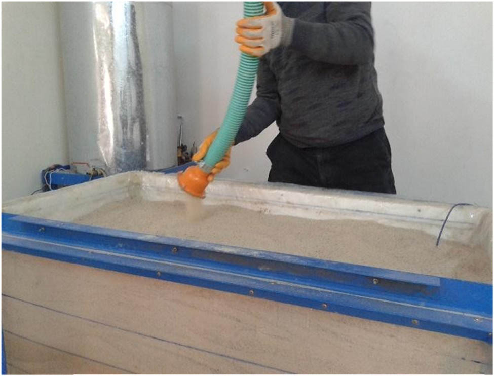
Soil raining of diffuser sieve.
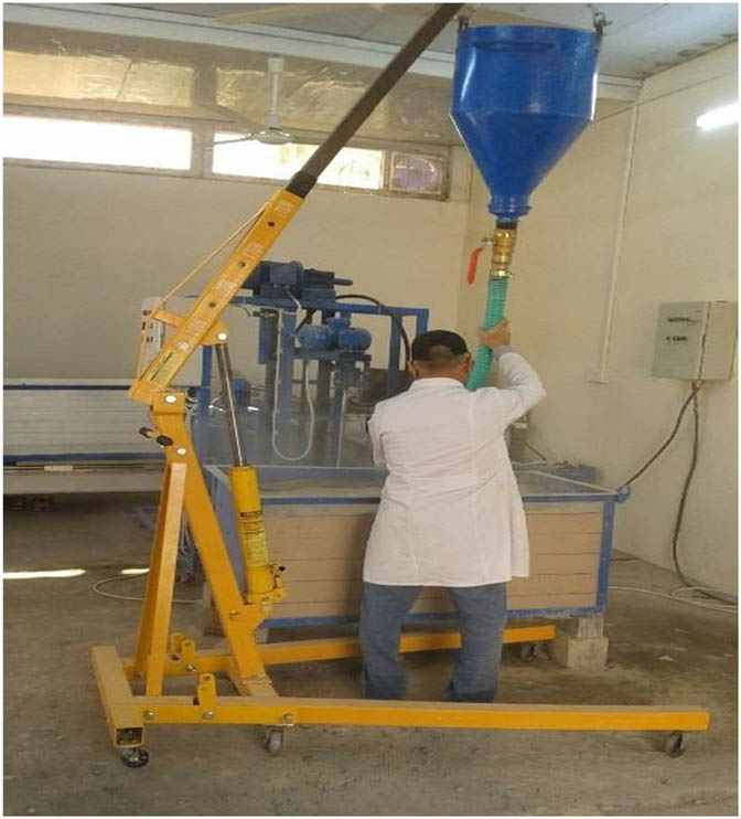
Soil raining by elevated funnel.
5 Low-pressure laboratory injecting process
After mixing the injection materials (separately in a bucket) according to the required proportions, the injection fluid is poured into the mixing tank. Then, the mixing motor is operated according to the suitable rotation speed by the variable frequency drive inverter on the control board.
The injection pump is operated by circulating the injection fluid from the bottom of the mixing tank through the pipe system and returning it to the top inlet of the mixing tank to ensure the injection pump operates appropriately.
Then, the drilling-injection rod is rotated and lowered into the sand box.
Before the injection process, a trial injection pumping (pumping a small amount of injection fluid over the soil surface) is carried out to ensure the proper operation of the nozzle. This initial injection process is vital to guarantee the non-plugging of nozzles (by sand grains intrusion) and injection continuity operation during the soil drilling and injecting process.
The injecting process is performed on the soil box by directing the platform injecting system downward and rotating (at 50 rpm revolution speed) the drilling and injecting rod in a clockwise direction. The injection process is performed in two stages.
The first injecting stage is associated with the downward drilling process of the injecting hole with a suitable fluid injecting pressure to stabilize the hole wall-sides.
The second stage (primary injection process) starts upward after the injection rod reaches the hole bottom of the soil box. From the control board, the rod rotation is reversed in the counterclockwise direction, and the platform grouting system is directed upwardly at the previously prescribed speed with the required injection pressure of pumped fluid according to the diaphragm pressure gauge.
During the injection process, some spoils flow from the injection hole surface to be removed from the soil box surface.
The lifting process for the drilling and injecting system platform continues during the injecting process until the nozzles reach the soil box surface, which is the end of the soil injecting column model performance process that leads to a consistent and homogenous injected column model.
During the soil injecting process, there is a lowering in the surface area of the injected column model (local densification for injection leading to shortening of the injected column model’ length) to be substituted with the same soil properties mixed with the upward spoiled injected fluid.
The injection process continued by moving to another location of the soil box until the required number of column model were injected (Plate 7).
After the injection of column model, the curing process is started by immersing them in a suitable water basin for a 28 days curing period (Plate 8).
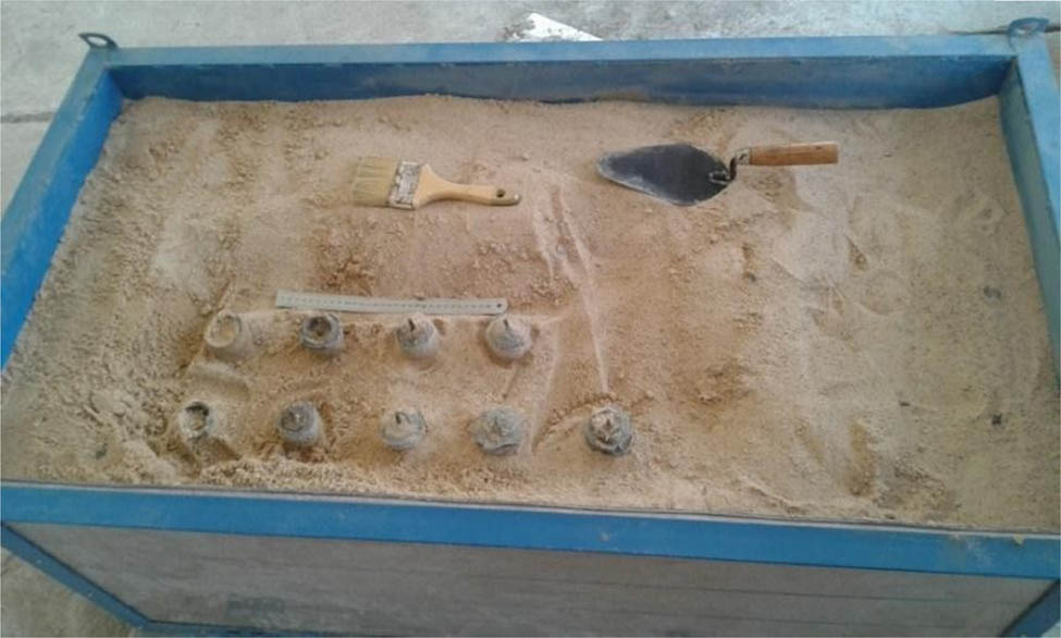
Grouted columns models.
Grouted columns models with diameters of 4–8 cm.
6 Unconfined compression test (UCT) results
Most testing programs stated in experimental research works use the unconfined compressive apparatus to investigate the influencing factors on the validity of improving the soil by grouted cement. The UCT is essential for the acquisition of expertise concerning soil cement injection assessment. It is also uncomplicated and quick, while being reliable and inexpensive. In this study, the unconfined compressive apparatus tested two sample groups of the low-pressure injected model columns (LPIMCs). The first sample group was cut from randomly chosen LPIMCs for OPC binder with 0.8, 1, and 1.3 W/C ratios. The other sample group was cut from randomly chosen LPIMCs for SF binder (10% by cement weight added to water and cement mix with 1, 1.3, and 1.6 W/C ratios). An automatic loading apparatus with a maximum capability of 50 kN equipped with a calibrated load cell and data logger for data acquisition was utilized for the tests.
According to ASTM D2166 [30], the samples were centrally loaded at a displacement rate of 1.2 mm/min up to the failure to obtain the maximum applied load. The tests were performed on identical samples for each binder group to minimize the variation in the testing conditions and materials. Because the data error was less than 5%, the obtained results were validated. The test results are listed in Table 2. By utilizing the CurveExpert Professional software version (2.7.3) for generating high-quality results using a cross-platform solution for curve fitting and data analysis, the trend of UCS and the W/C ratio relation for improving both the binders (Figures 2 and 3) revealed the same behavior as those shown in the previous studies [31]. The data for mathematical modeling showed a high coefficient of determination (R 2) for both relations.
Average UCT results of grouted cement and chemical grouted columns samples
| No. | Binder type | W/C | Average UCT (MPa) after 28 days of curing |
|---|---|---|---|
| 1 | OPC + 10% SF | 1 | 22 |
| 2 | OPC + 10% SF | 1.3 | 18 |
| 3 | OPC + 10% SF | 1.6 | 12 |
| 4 | OPC | 0.8 | 14 |
| 5 | OPC | 1 | 12 |
| 6 | OPC | 1.3 | 10 |
Unconfined compression strength (UCS) – W/C ratio for OPC binder.
UCS – W/C ratio for SF binder.
7 Conclusion
In specific cases, a preliminary trial for a cement injection operation must be performed on an alternative site where the soil properties should be identical to those of the construction site’s soil. After this trial, the grouted columns are excavated for a field checkup and to perform the required test. In performing trials of the jet grouting method, finding a site similar to the job site is not always feasible. It can be expensive and time-consuming, and it may not even lead to desired results. Therefore, the utilization of a low-pressure injection setup to model the cement grouting improvement technique is essential in geotechnical designs.
The main benefit of manufacturing a low-pressure injection setup is to determine the suitable ranges of the influencing injection operational factors (like grout pressure in kPa, flow rate in l/min., diameter and number of nozzles, lifting/penetrating rate in cm/min. and rotating speed in rev/min. of the drilling and injection shafts) affecting the injection process of an injected binder for improving a given soil in order to obtain consistent or homogeneous low-pressure injected model column samples.
The low-pressure injection laboratory setup is a suitable tool for model improvement for almost all soil types (most suitable for sandy soils) depending on injection operational factors, cement type (or its fineness) or binder type, and soil characteristics.
Methodologically or systematically performing the UCTs on representative samples of the low-pressure injected column models has considerable importance in validating the binder injectability process in terms of the homogeneity and reproducibility of these samples.
In this study, the objective for performing UCTs was to determine the effect of the W/C ratio factor on the strength of low-pressure injected model columns for improving both the methods. It was revealed that at the same W/C ratio for both soil binder types, the UCTs results for samples of the SF addictive binder are higher than that (about double) for samples of the OPC binder only. So, the influences of SF on the characteristics of injected soil samples were recognized.
The paper methodology emphasized the design and local manufacture of a low-pressure injection laboratory setup for modeling a column or a pile injection process. A comparison between two injected binder types was performed using this setup by carrying out UCTs on representative samples of low-pressure injected model columns, so the importance was on the W/C ratio as a primary variable for both the binder types and keeping the SF as a constant parameter for the other binder (so 1% of SF was used for this purpose).
For both binder types, the UCS results of the low-pressure injected column model samples increase with a decrease in the W/C ratio.
From a sustainable point of view, using SF as a chemical additive to the cement–water mixture for improving loose sand can lead to higher strength and less consumed cement but at a higher cost.
-
Funding information: The researchers affirm that no finance was received.
-
Author contributions: All researchers have been responsible for this document’s whole enclosure and accepted its handing over.
-
Conflict of interest: The researchers express no contradictory interests.
References
[1] Jehan B. Improvement of bearing capacity of sandy soil by grouting. Sarhad Univ Int J Basic Appl Sci. 2017;5(1):33–9.Suche in Google Scholar
[2] Croce P, Flora A, Modoni G. Jet grouting technology, design and control. Boca Raton (FL), USA: CRC Press; 2014.10.1201/b16411Suche in Google Scholar
[3] Kumar S. A study on the engineering behaviour of grouted loose sandy soils [dissertation]. Kochi: Cochin University of Science and Technology; 2010.Suche in Google Scholar
[4] Nikbakhtan B. Development of thermal-insulating soilcrete using laboratory jet grouting setup [dissertation]. Edmonton, Canada: University of Alberta; 2015.Suche in Google Scholar
[5] Khalili HD, Ghalandarzadeh A, Moradi M, Karimzadeh R. Effect of the distribution pattern of D.S.M. columns on the efficiency of liquefaction mitigation. Sci Iran. 2020;27(5):2198–208.Suche in Google Scholar
[6] Dano C, Derache N. Grout injection in the laboratory. In: Ochiai H, Omine K, Otani J, Yasufuku N, editors. Landmarks in Earth Reinforcement: Proceedings of the International Symposium on Earth Reinforcement; 2001 Nov 14–16; Fukuoka, Japan. CRC Press, 2001. p. 21–27.Suche in Google Scholar
[7] Akin M, Akin M, Çiftçi A, Bayram BB. The effect of jet-grouting on the cyclic stress ratio (C.S.R.) for the mitigation of liquefaction. Elektronik Mesleki Gelişim ve Araştırma Dergisi. 2015;1:9–20.Suche in Google Scholar
[8] Li SC, Sha F, Liu RT, Zhang QS, Li ZF. Investigation of fundamental properties of microfine cement and cement-slag grouts. Constr Build Mater. 2017;153:965–74.10.1016/j.conbuildmat.2017.05.188Suche in Google Scholar
[9] Kumar GS, Sumanth MK, Samuel M. A review paper on stabilization of sandy soil using cement grouting technique. J Crit Rev. 2020;7(14):902–8.10.31838/jcr.07.14.160Suche in Google Scholar
[10] Njock PGA, Shen JS, Modoni G, Arulrajah A. Recent advances in horizontal jet grouting (H.J.G.). An overview Arab J Sci Eng. 2018;43(4):1543–60.10.1007/s13369-017-2752-3Suche in Google Scholar
[11] Sedighi P, Schweiger HF, Wehr WJ. Effect of jet-grout columns on the seismic response of layered soil deposits. ASCE Int J Geomech. 2017;17(3):04016085.10.1061/(ASCE)GM.1943-5622.0000771Suche in Google Scholar
[12] Guler E, Secilen GG. Jet grouting technique and strength properties of jet grout columns. IOP J Phys Conf Ser. 2021;1928(1):012006.10.1088/1742-6596/1928/1/012006Suche in Google Scholar
[13] Shen SL, Wang ZF, Cheng WC, Estimation of lateral displacement induced by jet grouting in clayey soils. Geotechnique. 2017;67(7):621–30.10.1680/jgeot.16.P.159Suche in Google Scholar
[14] Dano C, Hicher PY, Tailliez S. Engineering properties of grouted sands. J Geotech Geoenviron. 2004;130(3):328–38.10.1061/(ASCE)1090-0241(2004)130:3(328)Suche in Google Scholar
[15] Mollamahmutoglu M, Yilmaz Y, Kutlu I. Grouting performance of microfine cement and silica fume mix into sands. J ASTM Int. 2007;4(4):1–7.10.1520/JAI100462Suche in Google Scholar
[16] Schwarz LG, Krizek RJ. Effect of preparation technique on permeability and strength of cement-grouted sand. Geotech Test J. 1994;17(4):434–43.10.1520/GTJ10304JSuche in Google Scholar
[17] Olgun M, Kanat A, Senkaya A, Erkan IH. Investigate the properties of jet grouting columns with fine-grained cement and silica fume. Constr Build Mater. 2021;267:120637.10.1016/j.conbuildmat.2020.120637Suche in Google Scholar
[18] AL-Kinani AM, Mahmood DA. Field study of the effect of jet grouting parameters on strength-based on tensile and unconfined compressive strength. IOP Conf Ser Mat Sci Eng. 2020;737:012083.10.1088/1757-899X/737/1/012083Suche in Google Scholar
[19] Kazemian S, Huat BBK, Prasad A, Barghchi M. A review of stabilization of soft soils by injection of chemical grouting. Aust J Basic Appl Sci. 2010;4(12):5862–8.Suche in Google Scholar
[20] Kazemian S, Huat BBK. Assessment of stabilization methods for soft soils by admixtures. International Conference on Scientific & Social Science Research (CSSR 2010); 2010 Dec 5–7; Kuala Lumpur, Malaysia. IEEE, 2011. p. 118–21.10.1109/CSSR.2010.5773714Suche in Google Scholar
[21] U.S. Army Corps of Engineers, Engineering Manual NO. EM 1110-1-3500, “Engineering and Design Chemical Grouting”, Department of the Army U.S. Army Corps of Engineers Washington, DC; 1995.Suche in Google Scholar
[22] Shroff AV, Shah DL. Grouting technology in tunnelling and dam construction. 2nd ed. Amsterdam, Netherlands: A.A. Balkema; 1999.Suche in Google Scholar
[23] U.S. Department of Transportation, Federal Highway Administration. Ground modification methods reference manual. Vol. II. Publication No. FHWA-NHI-16-028; 2017.Suche in Google Scholar
[24] Aldred JM, Holland TC, Morgan DR, Roy DM, Bury MA, Hooton RD, et al. Guide for the Use of Silica Fume in Concrete. Farmington Hills (MI), USA: ACI Commitee; 2006.Suche in Google Scholar
[25] Raveendran KG, Rameshkumar V, Saravanan M, Kanmani P, Sudhakar S. Performance of silica fume on strength and durability of concrete. Int J Innovative Res Sci Eng Technol. 2015;4(10):10162–6.Suche in Google Scholar
[26] Li H, Xiao HG, Yuan J, Ou JP. Microstructure of Cement Mortar with Nano-Particles. Compos Part B Eng. 2004;35(2):185–9.10.1016/S1359-8368(03)00052-0Suche in Google Scholar
[27] Hasanzadeh A, Shooshpasha I. Effects of silica fume on cemented sand using ultrasonic pulse velocity. J Adhes Sci Technol. 2019;33:1184–200.10.1080/01694243.2019.1582890Suche in Google Scholar
[28] Wilson M, Kannangara K, Smith G, Simmons M, Raguse B. Nanotechnology basic science and emerging technologies. 1st ed. Boca Raton (FL), USA: CRC Press; 2002.10.1201/9781420035230Suche in Google Scholar
[29] Zhang P, Li Q. Effect of silica fume on durability of concrete composites containing fly ash. Sci Eng Compos Mater. 2013;20(1):57–65.10.1515/secm-2012-0081Suche in Google Scholar
[30] ASTM D2166. Standard test method for unconfined compressive strength of cohesive soil. West Conshohocken (PA), USA: ASTM International; 2016.Suche in Google Scholar
[31] Federal Highway Administration Design manual: Deep mixing for embankment and foundation support. Publication Number: FHWA-HRT-13-046; 2013.Suche in Google Scholar
© 2023 the author(s), published by De Gruyter
This work is licensed under the Creative Commons Attribution 4.0 International License.
Artikel in diesem Heft
- Research Articles
- The mechanical properties of lightweight (volcanic pumice) concrete containing fibers with exposure to high temperatures
- Experimental investigation on the influence of partially stabilised nano-ZrO2 on the properties of prepared clay-based refractory mortar
- Investigation of cycloaliphatic amine-cured bisphenol-A epoxy resin under quenching treatment and the effect on its carbon fiber composite lamination strength
- Influence on compressive and tensile strength properties of fiber-reinforced concrete using polypropylene, jute, and coir fiber
- Estimation of uniaxial compressive and indirect tensile strengths of intact rock from Schmidt hammer rebound number
- Effect of calcined diatomaceous earth, polypropylene fiber, and glass fiber on the mechanical properties of ultra-high-performance fiber-reinforced concrete
- Analysis of the tensile and bending strengths of the joints of “Gigantochloa apus” bamboo composite laminated boards with epoxy resin matrix
- Performance analysis of subgrade in asphaltic rail track design and Indonesia’s existing ballasted track
- Utilization of hybrid fibers in different types of concrete and their activity
- Validated three-dimensional finite element modeling for static behavior of RC tapered columns
- Mechanical properties and durability of ultra-high-performance concrete with calcined diatomaceous earth as cement replacement
- Characterization of rutting resistance of warm-modified asphalt mixtures tested in a dynamic shear rheometer
- Microstructural characteristics and mechanical properties of rotary friction-welded dissimilar AISI 431 steel/AISI 1018 steel joints
- Wear performance analysis of B4C and graphene particles reinforced Al–Cu alloy based composites using Taguchi method
- Connective and magnetic effects in a curved wavy channel with nanoparticles under different waveforms
- Development of AHP-embedded Deng’s hybrid MCDM model in micro-EDM using carbon-coated electrode
- Characterization of wear and fatigue behavior of aluminum piston alloy using alumina nanoparticles
- Evaluation of mechanical properties of fiber-reinforced syntactic foam thermoset composites: A robust artificial intelligence modeling approach for improved accuracy with little datasets
- Assessment of the beam configuration effects on designed beam–column connection structures using FE methodology based on experimental benchmarking
- Influence of graphene coating in electrical discharge machining with an aluminum electrode
- A novel fiberglass-reinforced polyurethane elastomer as the core sandwich material of the ship–plate system
- Seismic monitoring of strength in stabilized foundations by P-wave reflection and downhole geophysical logging for drill borehole core
- Blood flow analysis in narrow channel with activation energy and nonlinear thermal radiation
- Investigation of machining characterization of solar material on WEDM process through response surface methodology
- High-temperature oxidation and hot corrosion behavior of the Inconel 738LC coating with and without Al2O3-CNTs
- Influence of flexoelectric effect on the bending rigidity of a Timoshenko graphene-reinforced nanorod
- An analysis of longitudinal residual stresses in EN AW-5083 alloy strips as a function of cold-rolling process parameters
- Assessment of the OTEC cold water pipe design under bending loading: A benchmarking and parametric study using finite element approach
- A theoretical study of mechanical source in a hygrothermoelastic medium with an overlying non-viscous fluid
- An atomistic study on the strain rate and temperature dependences of the plastic deformation Cu–Au core–shell nanowires: On the role of dislocations
- Effect of lightweight expanded clay aggregate as partial replacement of coarse aggregate on the mechanical properties of fire-exposed concrete
- Utilization of nanoparticles and waste materials in cement mortars
- Investigation of the ability of steel plate shear walls against designed cyclic loadings: Benchmarking and parametric study
- Effect of truck and train loading on permanent deformation and fatigue cracking behavior of asphalt concrete in flexible pavement highway and asphaltic overlayment track
- The impact of zirconia nanoparticles on the mechanical characteristics of 7075 aluminum alloy
- Investigation of the performance of integrated intelligent models to predict the roughness of Ti6Al4V end-milled surface with uncoated cutting tool
- Low-temperature relaxation of various samarium phosphate glasses
- Disposal of demolished waste as partial fine aggregate replacement in roller-compacted concrete
- Review Articles
- Assessment of eggshell-based material as a green-composite filler: Project milestones and future potential as an engineering material
- Effect of post-processing treatments on mechanical performance of cold spray coating – an overview
- Internal curing of ultra-high-performance concrete: A comprehensive overview
- Special Issue: Sustainability and Development in Civil Engineering - Part II
- Behavior of circular skirted footing on gypseous soil subjected to water infiltration
- Numerical analysis of slopes treated by nano-materials
- Soil–water characteristic curve of unsaturated collapsible soils
- A new sand raining technique to reconstitute large sand specimens
- Groundwater flow modeling and hydraulic assessment of Al-Ruhbah region, Iraq
- Proposing an inflatable rubber dam on the Tidal Shatt Al-Arab River, Southern Iraq
- Sustainable high-strength lightweight concrete with pumice stone and sugar molasses
- Transient response and performance of prestressed concrete deep T-beams with large web openings under impact loading
- Shear transfer strength estimation of concrete elements using generalized artificial neural network models
- Simulation and assessment of water supply network for specified districts at Najaf Governorate
- Comparison between cement and chemically improved sandy soil by column models using low-pressure injection laboratory setup
- Alteration of physicochemical properties of tap water passing through different intensities of magnetic field
- Numerical analysis of reinforced concrete beams subjected to impact loads
- The peristaltic flow for Carreau fluid through an elastic channel
- Efficiency of CFRP torsional strengthening technique for L-shaped spandrel reinforced concrete beams
- Numerical modeling of connected piled raft foundation under seismic loading in layered soils
- Predicting the performance of retaining structure under seismic loads by PLAXIS software
- Effect of surcharge load location on the behavior of cantilever retaining wall
- Shear strength behavior of organic soils treated with fly ash and fly ash-based geopolymer
- Dynamic response of a two-story steel structure subjected to earthquake excitation by using deterministic and nondeterministic approaches
- Nonlinear-finite-element analysis of reactive powder concrete columns subjected to eccentric compressive load
- An experimental study of the effect of lateral static load on cyclic response of pile group in sandy soil