Robot indoor navigation point cloud map generation algorithm based on visual sensing
-
Qin Zhang


Abstract
At present, low-cost Red Green Blue Depth (RGB-D) sensors are mainly used in indoor robot environment perception, but the depth information obtained by RGB-D cameras has problems such as poor accuracy and high noise, and the generated 3D color point cloud map has low accuracy. In order to solve these problems, this article proposes a vision sensor-based point cloud map generation algorithm for robot indoor navigation. The aim is to obtain a more accurate point cloud map through visual SLAM and Kalman filtering visual-inertial navigation attitude fusion algorithm. The results show that in the positioning speed test data of the fusion algorithm in this study, the average time-consuming of camera tracking is 23.4 ms, which can meet the processing speed requirement of 42 frames per second. The yaw angle error of the fusion algorithm is the smallest, and the ATE test values of the algorithm are smaller than those of the Inertial measurement unit and Simultaneous-Localization-and-Mapping algorithms. This research algorithm can make the mapping process more stable and robust. It can use visual sensors to make more accurate route planning, and this algorithm improves the indoor positioning accuracy of the robot. In addition, the research algorithm can also obtain a dense point cloud map in real time, which provides a more comprehensive idea for the research of robot indoor navigation point cloud map generation.
1 Introduction
Under the background of the continuous development and progress of science and technology in the new era. With the continuous expansion of the application scenarios of indoor intelligent mobile robots, the requirements for robot technology are also constantly improving. Therefore, robot multi-sensor fusion technology has gradually been favored by many researchers in related fields [1,2,3]. At present, the image point cloud generation of robot navigation and positioning mainly adopts two methods. In the field of computer vision, after completing camera calibration, corresponding point pairs are established in multiple images and then the three-dimensional coordinates are reconstructed in the scene, that is three-dimensional reconstruction; this is 3D reconstruction Structure from Motion (SfM), and Simultaneous-Localization-and-Mapping (SLAM). Among them, SLAM of robots in unknown environments is the key research point in the field of robot navigation and positioning. And it is also the premise for robots to complete instructions [4]. However, for robots that need to work in more complex environments, traditional single-visual SLAM has been unable to satisfy its ability to perceive environmental information. Because the robot can only obtain information about a certain dimension in the environment through a single visual sensor. The limited environmental information cannot provide it with more environmental features to assist in positioning, resulting in low mapping quality and low navigation and positioning accuracy [5]. Although the depth camera Red Green Blue Depth Map (RGB-D) of visual SLAM can provide more information than traditional cameras, the depth camera RGB-D is limited by its own hardware equipment. It is easily affected by light, and the robot is prone to tracking failure under conditions such as high-speed rotation. The inertial sensor has the advantages of high output frequency of attitude estimation and high output accuracy under high-speed rotation. But the output of its attitude information will also have the problem of large error accumulation in the case of long-term work: the robot’s autonomous working ability in an indoor environment, the accuracy of navigation and positioning, and the lack of map construction quality. The research is based on improving the robot’s pose and pose estimation accuracy. Visual SLAM and Kalman filter visual-inertial navigation are studied. The pose is fused to generate a real-time and accurate robot indoor navigation point cloud map.
2 Related work
Under the background of the continuous development and progress of science and technology in the new era, as the application scenarios of indoor intelligent mobile robots continue to expand, the requirements for robot navigation and positioning technology are also constantly improving. For robots that need to work in more complex environments, traditional single sensors have been unable to meet their needs for the perception of environmental information. Therefore, scholars and experts at home and abroad have deeply discussed the generation algorithm of indoor robot navigation point cloud maps. In order to improve the trajectory planning accuracy of the detection robot, Zhang et al. proposed a new method for generating non-destructive testing trajectories of robots based on preprocessed point cloud data. The results show that the method is reliable [6]. In order to obtain an accurate environmental cognitive map and achieve the goal of bionic robot navigation, experts and scholars such as Yu et al. proposed a navigation algorithm to construct an accurate environmental cognitive map, and experiments show that the algorithm is accurate [7]. The purpose of the research is to achieve precise positioning and obtain faster tracking speed and better depth map, researchers such as Wen et al. proposed an algorithm for constructing dense maps through a fast stereo vision inertial navigation system. The results show that the algorithm has certain advantages. In order to reliably estimate object recognition and pose, researchers such as Wang et al. proposed a new global point cloud descriptor [8]. The results show that this method can solve this problem well and guide the robot to grasp objects with mirror poses [9]. Liu and other scholars proposed a multi-resolution auxiliary historical point cloud matching algorithm in order to solve the problems of the traditional two-dimensional lidar-related scanning matching algorithms, such as a large amount of calculation and poor real-time performance. The results verify the effectiveness and accuracy of the algorithm [10]. In order to ensure that non-expert users can plan robot trajectories intuitively and effectively, scholars such as Zhang et al. proposed a new trajectory planning system. The experimental results show that the system is effective and has certain advantages [11].
In order to improve the accuracy and performance of robot navigation, researchers such as Yang et al. proposed a two-layer ant colony optimization algorithm that can be used for the autonomous navigation of robots. The experiments show that the algorithm is efficient [12]. In order to explore the method of robot navigation in a dynamic environment, experts such as Wang et al. proposed a real-time projection of a 3D point cloud to a 2D static global map based on SLAM and constructed a 2D dynamic global map system. Experiments show that the system is effective and reliable [13]. Li et al. proposed an algorithm for reconstructing remote indoor environments through incremental point cloud compression, and the purpose is to improve the effectiveness of the 3D mapping based on remote operation of the robot in a dangerous area working environment. The research verifies the applicability of this method [14]. In order to improve the accuracy and resolution of all-focus images and 3D point clouds, Zhao et al. proposed a 3D vision sensing method based on focus superposition. Experiments show that this technology is effective and superior [5]. In order to solve the problem that only the closest point is iterated in the dynamic environment and other dangerous environments with uncertainty, and the accurate point cloud registration performance cannot be achieved, scholars such as Li et al. proposed a six-degree-of-freedom attitude estimation and mapping based on Segmented scan matching framework, and experiments show that this method can obtain higher pose estimation accuracy [15].
From the research results of domestic and foreign scholars and experts on the generation algorithm of robot indoor navigation point cloud map, it can be seen that the algorithm for pose estimation based on visual sensors such as cameras has gradually matured, but the current research on the accuracy of robot indoor navigation at home and abroad is still insufficient. At the same time, the quality of map construction and other issues are still difficult problems that need to be solved. Therefore, based on visual sensing, this research uses visual SLAM and Kalman filter visual-inertial navigation attitude fusion algorithm to generate a robot indoor navigation point cloud map.
3 Robot indoor navigation point cloud map generation algorithm based on visual sensing
3.1 Robot indoor navigation point cloud pose estimation based on visual SLAM algorithm
Very effective representation of a robot navigation map, which is mainly obtained by laser point cloud and image point cloud [16,17]. The 3D laser scanner used in the 3D point cloud is expensive, bulky, and complicated in data processing. There are two main methods of generating image point clouds, SfM and SLAM. SfM is difficult to obtain the real size of the 3D scene structure in the processing process, and cannot meet the high real-time requirements. With the development of sensor technology and computer vision technology, SLAM in the field of robotics is more suitable for application scenarios with high real-time requirements. The sensor commonly used in visual SLAM is the camera. Among them, the depth camera (RGB-D) can provide more information than traditional cameras, and it is not necessary to calculate the depth as time-consuming and laborious as monocular or binocular. In terms of SLAM, it is mainly used indoor. A color image
Given the pixel coordinates of the image
The definition of camera rigid body transformation is shown in equation (3):
In equation (3), it
In equation (4), it
Pose
In equation (6), the corresponding three-dimensional point coordinates in space are represented. By optimizing the projection error of the color image, the pose of the camera can be obtained as shown in equation (7):
In order to improve the robustness of camera tracking, when the camera pose cannot be obtained, the camera pose is
In equation (8),
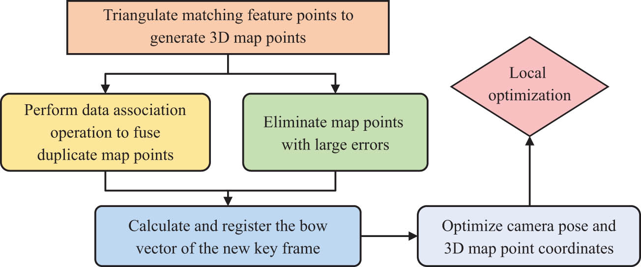
Processing steps of keyframes.
As shown in Figure 1, for the newly added keyframes
In equation (9), it
After jointly optimizing the back-projection error of the dark image and the projection error of the color image, the result obtained is shown in equation (11):
In equation (11),

Algorithm flow of robot indoor navigation point cloud pose estimation based on RGB-D.
As shown in Figure 2, the study uses the ORB (Oriented FAST and Rotated BRIEF, ORB) operator to quickly extract and match the visual features of the color sequence images captured by the depth camera and then combines the Iterative Closest Point (ICP) algorithm and Real-time estimation of camera pose. And the ICP error constraint in the camera pose optimization operation is added, and then the graph optimization algorithm is use to jointly optimize the color image projection error obtained by the depth camera and the back-projection error of the depth image, and finally relatively accurate camera pose and 3D sparseness point cloud are obtained. However, in visual SLAM, the tracking drift of the camera is unavoidable due to the continuous accumulation of attitude errors.
3.2 Point cloud map based on visual SLAM and Kalman filter visual inertial navigation attitude fusion algorithm
In fact, the real-time performance of camera pose estimation based only on the visual SLAM algorithm in an indoor environment is still not high, and the output frequency is low, which is prone to tracking failure under high-speed rotation. Inertial measurement unit (IMU) plays an important role in navigation and positioning. The inertial sensor has a high output frequency for attitude estimation and high output accuracy under high-speed rotation [18]. The establishment of IMU kinematics model relies on the Kalman filter to achieve an accurate output of attitude. The visual-inertial navigation attitude fusion algorithm based on the Kalman filter is shown in Figure 3.

Algorithm flow of visual-inertial navigation attitude fusion based on Kalman filter.
As shown in Figure 3, you need to build a map immediately and start positioning to obtain IMU data and image frames. Then, the ORB descriptor is extracted and synchronized with the image frame at the same time. The pose is initialized by combining the image, IMU position, and attitude information. Next, Kalman filtering is performed and stopped after obtaining the updated data of IMU. The research combines the advantages of the two pose estimation algorithms, using the attitude information output by the inertial navigation as the predicted value, and then takes the attitude information obtained by the visual slam as the observation value. Kalman filter is an optimal autoregressive data processing algorithm. Before using this algorithm, it is necessary to obtain the state equation and observation equation of the system. The state equation of the inertial system is shown in equation (12):
In equation (12),
In order to obtain the state transition matrix
In equation (14),
In equation (15),
And the noise covariance matrix are
In equation (17),
The update process of the Kalman filter can be obtained from equation (18), as shown in equation (19) [23]:
In equation (19),
The initial value obtained by equation (20) and its parameters are shown in equation (21):
Since the initial value of the system noise covariance matrix determines the initial filter gain of the system, but it has little effect on the convergence speed, it will be
When
In general, it is not necessary to re-adjust the initial parameter values before replacing the IMU device. The overall algorithm flow of robot indoor navigation point cloud map generation based on visual SLAM and Kalman filter visual-inertial navigation attitude fusion is shown in Figure 4.
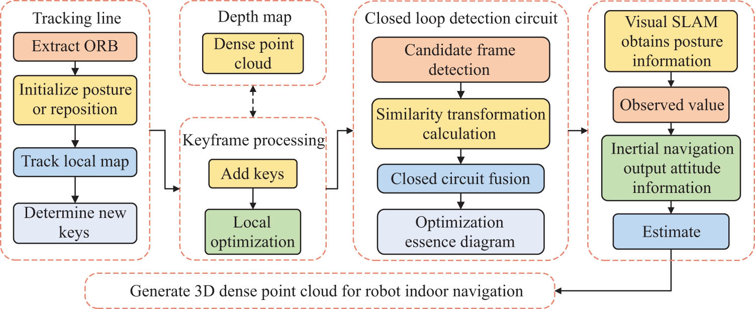
Algorithm flow of robot indoor navigation point cloud map generation based on visual sensing.
As shown in Figure 4, the algorithm for generating the point cloud map of robot indoor navigation is mainly divided into three modules. The tracking line mainly obtains the camera pose and the sparse point cloud through the depth camera of the visual SLAM, and then determines the new keyframe and analyzes the keyframe. It makes reasonable additions or deletions and performs point cloud splicing and fusion. Finally, the closed-loop detection is used to optimize the essential map, and the attitude information output by visual SLAM and inertial navigation is used as the observed value and the predicted value to improve the robustness of the attitude acquisition process and finally obtain a more accurate robot indoor navigation point cloud map [24,25].
4 Experimental analysis of point cloud map generation for robot indoor navigation based on visual sensing
The experiment, Turtlebot as a robot platform, is equipped with a depth camera-Kinect Xbox 2 generation camera, and Intel Core I5-3230CPU is installed with a laptop computer, and 64 bit system is used as the main control computer, which is responsible for SLAM information processing and system operation control. The research by Debian Sid extracts the visual features of the sequence images captured by the depth camera and then obtains the matching set of feature points from the adjacent image frames to estimate the camera pose in real time and its motion trajectory in the air as shown in Figure 5(a). The depth image obtained by the depth camera to match the set of feature points between adjacent images is used, and then the triangulation operation to reconstruct the spatial 3D point coordinates corresponding to the pixels of the image is performed, and the obtained sparse 3D point cloud is shown in Figure 5(b).

(a) Camera-estimated trajectory and (b) Sparse 3D point cloud.
As shown in Figure 5, in space, the motion trajectory of the camera is almost the same as the line connecting the coordinate points of the three-dimensional sparse point cloud. In order to reduce the influence of error accumulation and obtain a globally unified map, loop detection based on SLAM is introduced in the processing flow of SLAM. When processing keyframes, the newly generated key positive vector is registered, and in the loop detection stage, the keyframes that share the same visual word as the current keyframe are retrieved from the constructed vector database and used as candidates for loops. Then, the similarity between the candidate and the current keyframe is calculated, the key frame whose similarity exceeds a certain threshold as the loop candidate is taken, and its adjacent frame as the loop candidate are selected and is used to calculate the transformation relationship between it and the current frame, taking a sufficient number of keyframes as loop keyframes and ensuring that they are geometrically consistent with the current frame. In order to test the efficiency of the research method, the key steps are measured for speed, and the performance test results are shown in Table 1.
Performance test results
| Map construction | Camera tracking | ||||||
|---|---|---|---|---|---|---|---|
| Number of calls | 174 | Minimum (ms) | 17.6 | Number of calls | 3,782 | Minimum (ms) | 5.6 |
| Average (ms) | 340.9 | Average (ms) | 23.4 | ||||
| Maximum (ms) | 602.6 | Maximum (ms) | 85.0 | ||||
| Total (s) | 59.8 | Total (s) | 88.9 | ||||
As shown in Table 1, it can be seen from the positioning speed test data that the average time-consuming of camera tracking is 23.4 ms, which can meet the processing speed requirement of 42 frames per second. It can be seen from the program performance measurement and robot test results that the research method can achieve indoor real-time requirements for robot navigation to generate point cloud maps. The experiment uses Intel Lab the company’s IMU, its output frequency can reach 200 Hz, its model is OS3DM, and the IMU is fixed on the Kinect camera. The pose estimation information of the visual SLAM algorithm is used as the observation value, and the output value of the IMU is corrected. In order to ensure the accuracy of the fusion algorithm, the IMU and the Kinect camera need to be uniformly aligned through the transformation between the coordinate systems, and then the time filter mechanism under ROS is used to match the topic timestamps published by the two, and the data are aligned through the software–time synchronization. Figure 6 shows the visual-inertial navigation attitude comparison and ground truth map.

Visual inertial navigation attitude. (a) Visual inertial navigation posture comparison diagram. (b) True value diagram of visual inertial navigation posture.
It can be seen from Figure 6a that, in a relatively short time, the attitude information output by IMU can meet the requirements, but after a period of operation, the output value has a relatively obvious drift due to the increase of the accumulated attitude error. The attitude information output by the visual SLAM algorithm also produces a certain error after long-term operation, and the error value is smaller than that of the IMU. The error value of the research algorithm is smaller than the output attitude error of IMU and SLAM. The algorithm uses the attitude information obtained by visual SLAM as the observation value to correct the output value of the IMU, which is close to the real value in Figure 6b. The visual-inertial navigation attitude error is sorted and counted, and the obtained results are shown in Table 2.
Statistics of attitude yaw angle error of visual inertial navigation system
| Algorithm type | Error type | Yaw angle error (°) |
|---|---|---|
| Fusion algorithm | Maximum error | 8.215 |
| Root mean square error | 2.143 | |
| RGBD-SLAM | Maximum error | 8.485 |
| Root mean square error | 2.768 | |
| IMU | Maximum error | 8.642 |
| Root mean square error | 2.904 |
From Table 2, the maximum error of the yaw angle of the research method is 8.215°, and its root mean square error is 2.143, which is smaller than the yaw angle error of the IMU and RGBD-SLAM algorithms, indicating that the accuracy of the research algorithm is to a certain extent improved above. Furthermore, the accuracy of the experiment is verified, and the data set TUM-RGBD is used for the accuracy evaluation test. The absolute trajectory error between the estimated camera trajectory and the real trajectory is measured ATE as the ATE absolute trajectory error statistics are shown in Table 3.
Comparison of absolute trajectory error (ATE)
| Data set | Fusion algorithm | RGBD-SLAM | IMU |
|---|---|---|---|
| Fr1/xyz | 0.012 | 0.015 | 0.027 |
| Fr1/rpy | 0.028 | 0.025 | 0.132 |
| Fr1/desk | 0.020 | 0.024 | 0.058 |
| Fr1/desk2 | 0.021 | 0.042 | 0.419 |
| Fr1/room | 0.057 | 0.083 | 0.312 |
| Fr1/360 | 0.018 | 0.080 | 0.914 |
| Fr1/teddy | 0.045 | 0.077 | 0.912 |
| Fr1/plant | 0.014 | 0.092 | 0.598 |
| Fr2/desk | 0.073 | / | / |
| Fr3/office | 0.010 | / | 0.065 |
As shown in Table 3, in the 10 data sets, the absolute error trajectory ATE of the camera calculated based on the fusion of visual SLAM and Kalman filter visual-inertial navigation attitude is the minimum of 0.010 and the maximum error of 0.073. The absolute trajectory error ATE of the IMU is a maximum of 0.092 and a minimum of 0.015. The absolute trajectory error ATE of the RGBD-SLAM algorithm is 0.914 at the maximum and 0.027 at the minimum. The absolute trajectory error ATE value of the fusion algorithm studied in each data set is smaller than that of the IMU and RGBD-SLAM algorithms. It can be seen from the test results that the accuracy and robustness of the camera pose estimated by this research method are better than the other two methods. The camera trajectory estimated by the research method is compared with the real value of the camera trajectory, and the results are shown in Figure 7.

Comparison between estimated value and true value of camera trajectory. (a) Fr1/desk, (b) Fr1/xyz, (c) Fr1/plant, and (d) Fr1/office.
It can be seen from Figure 7 that four representative camera trajectories are selected to show the difference between the estimated trajectory and the true trajectory. It is obvious from Figure 7(a) that the estimated value of the camera track is highly coincident with the real value and close to the ground live track. It can be seen from Figure 7(b) that although the trajectory of the true value is more complex, the trajectory estimated by the camera still has a good coincidence with it. Although the range of real trajectories in Figure 7(c) is expanded, the difference between estimated trajectories and real trajectories is very small. In Figure 7(d), the true value trajectory is open and closed, and the camera-estimated trajectory can accurately avoid the missing trajectory line, which is very close to the true value trajectory. The results show that the camera trajectory estimated by the fusion algorithm of visual SLAM and Kalman filtering visual-inertial navigation attitude can be very similar to the real value trajectory of the camera. Compared with IMU and RGBD-SLAM algorithms, the camera trajectory obtained by this algorithm is more accurate, real-time, and robust.
5 Conclusion
This research mainly focuses on the problem of point cloud map generation for robot indoor navigation and applies an algorithm based on visual sensing, which combines visual SLAM and Kalman filter visual-inertial navigation attitude. The experimental results show that the movement trajectory of the camera in space is roughly the same as the line connecting the coordinate points of the three-dimensional sparse point cloud, which proves the effectiveness of this method. In the positioning speed test data, the average time-consuming of camera tracking is 23.4 ms, which can meet the processing speed requirement of 42 frames per second and can realize the real-time requirement of robot indoor navigation point cloud map generation. It can be seen that the error value of the fusion algorithm in this study is smaller than the output attitude error of IMU and SLAM. The maximum error of the yaw angle of the research method is 8.215°, and its root mean square error is 2.143, which is smaller than the yaw angle error of the IMU and RGBD-SLAM algorithms, indicating that the accuracy of the research algorithm has been improved to a certain extent. The ATE test values of this research method are smaller than those of the IMU and RGBD-SLAM algorithms, and the camera trajectory estimated by this algorithm is very close to the true value of the camera trajectory in the data set. Although the fusion algorithm in this study has achieved good test results, it still lacks in establishing a dense 3D point cloud, and the follow-up research will focus on improving this aspect.
-
Conflict of interest: It is declared by the authors that this article is free of conflict of interest.
-
Data availability statement: All data generated or analysed during this study are included in this published article.
References
[1] Glibin ES, Shevtsov AA, Enik OA. Method of mobile robot indoor navigation by artificial landmarks with use of computer vision. J Phys Conf Ser. 2018;1015:032171.10.1088/1742-6596/1015/3/032171Search in Google Scholar
[2] Xu Y, Shmaliy YS, Ahn CK, Tian G, Chen X. Robust and accurate UWB-based indoor robot localisation using integrated EKF/EFIR filtering. IET Radar, Sonar Navigation. 2018;12(7):750–6.10.1049/iet-rsn.2017.0461Search in Google Scholar
[3] Wang H, Ren J. A semantic map for indoor robot navigation based on predicate logic. Int J Knowl Syst Sci. 2020;11(1):1–21.10.4018/IJKSS.2020010101Search in Google Scholar
[4] Zhu F, Zheng S, Wang X, He Y, Gui L, Gong L. Real-time efficient relocation algorithm based on depth map for small-range textureless 3D scanning. Sensors. 2019;19(18):3855.10.3390/s19183855Search in Google Scholar PubMed PubMed Central
[5] Zhao X, Liu C, Dou L, Qiu J, Su Z. 3D visual sensing technique based on focal stack for snake robotic applications. Results Phys. 2019;12:1520–8.10.1016/j.rinp.2019.01.045Search in Google Scholar
[6] Zhang Z, Zhang H, Yu X, Deng Y, Chen Z. Robotic trajectory planning for non-destructive testing based on surface 3D point cloud data. J Phys Conf Ser. 2021;1965(1):012148.10.1088/1742-6596/1965/1/012148Search in Google Scholar
[7] Yu N, Zhai Y, Yuan Y, Wang Z. A bionic robot navigation algorithm based on cognitive mechanism of hippocampus. IEEE Trans Autom Sci Eng. 2019;16(4):1640–52.10.1109/TASE.2019.2909638Search in Google Scholar
[8] Wen S, Liu X, Zhang H, Sun F, Sheng M, Fan S. Dense point cloud map construction based on stereo VINS for mobile vehicles. ISPRS J Photogrammetry Remote Sens. 2021;178(10):328–44.10.1016/j.isprsjprs.2021.06.009Search in Google Scholar
[9] Wang F, Liang C, Ru C, Cheng H. An improved point cloud descriptor for vision based robotic grasping system. Sensors. 2019;19(10):2225.10.3390/s19102225Search in Google Scholar PubMed PubMed Central
[10] Liu H, Luo S, Lu J. Correlation scan matching algorithm based on multi‐resolution auxiliary historical point cloud and lidar simultaneous localisation and mapping positioning application. IET Image Process. 2020;14:3596–601.10.1049/iet-ipr.2019.1657Search in Google Scholar
[11] Zhang HD, Liu SB, Lei QJ, He Y, Yang Y, Bai Y. Robot programming by demonstration: a novel system for robot trajectory programming based on robot operating system. Adv Manuf. 2020;8(2):216–29.10.1007/s40436-020-00303-4Search in Google Scholar
[12] Yang H, Qi J, Miao Y, Sun H, Li J. A new robot navigation algorithm based on a double-layer ant algorithm and trajectory optimization. IEEE Trans Ind Electron. 2019;66(11):8557–66.10.1109/TIE.2018.2886798Search in Google Scholar
[13] Wang X, Mizukami Y, Tada M, Matsuno F. Navigation of a mobile robot in a dynamic environment using a point cloud map. Artif Life Robot. 2021;26(1):10–20.10.1007/s10015-020-00617-3Search in Google Scholar
[14] Li Y, Gao J, Wang X, Chen Y, He Y. Depth camera based remote three-dimensional reconstruction using incremental point cloud compression. Computers Electr Eng. 2022;99:107767.10.1016/j.compeleceng.2022.107767Search in Google Scholar
[15] Li X, Du S, Li G, Li H. Integrate point-cloud segmentation with 3D LiDAR scan-matching for mobile robot localization and mapping. Sensors. 2019;20(1):237–7.10.3390/s20010237Search in Google Scholar PubMed PubMed Central
[16] Wang Y, Zhang Y, Wang S, Ji X. A massive laser point cloud data organization strategy based on the mixed model. J Phys Conf Ser. 2021;1757(1):012177–84.10.1088/1742-6596/1757/1/012177Search in Google Scholar
[17] Castilla G, Filiatrault M, McDermid GJ, Gartrell M. Estimating individual conifer seedling height using drone-based image point clouds. Forests. 2020;11(9):924–4.10.3390/f11090924Search in Google Scholar
[18] Jillella VR. Design and Implementation of an Inertial Navigation Unit using MEMS sensors. IOSR J Electron Commun Eng. 2019;14(6):1–5.Search in Google Scholar
[19] Sobamowo GM. Analytical solution of black-scholes model for pricing barrier option using method of partial Taylor series expansion. Earthline J Math Sci. 2022;10(2):439–56.10.34198/ejms.10222.439456Search in Google Scholar
[20] Pramanik S, Maiti I, Mandal T. A taylor series based fuzzy mathematical approach for multi objective linear fractional programming problem with fuzzy parameters. Int J Computer Appl. 2018;180(45):22–9.10.5120/ijca2018917154Search in Google Scholar
[21] Li W, Liao B, Xiao L, Lu R. A recurrent neural network with predefined-time convergence and improved noise tolerance for dynamic matrix square root finding. Neurocomputing. 2019;337(14):262–73.10.1016/j.neucom.2019.01.072Search in Google Scholar
[22] Chihabi Y, Ulrich S. Linear time-varying state transition matrix for spacecraft relative dynamics on highly elliptical orbits. Acta Astronautica. 2022;198:208–24.10.1016/j.actaastro.2022.05.056Search in Google Scholar
[23] Yuan J, Wang Y, Ji Z. A differentially private square root unscented Kalman filter for protecting process parameters in ICPSs. ISA Trans. 2020;104:44–52.10.1016/j.isatra.2019.12.010Search in Google Scholar PubMed
[24] Wang J, Zhang Y, Yan J. Attitude output of strapdown inertial navigation system based on laser gyro. Int J Circuits. 2020;14:863–74.10.46300/9106.2020.14.112Search in Google Scholar
[25] Bai D, Wang C, Zhang B, Yi X, Yang X. CNN feature boosted SeqSLAM for real-time loop closure detection. Chin J Electron. 2018;27(3):48–59.10.1049/cje.2018.03.010Search in Google Scholar
© 2023 the author(s), published by De Gruyter
This work is licensed under the Creative Commons Attribution 4.0 International License.
Articles in the same Issue
- Research Articles
- Salp swarm and gray wolf optimizer for improving the efficiency of power supply network in radial distribution systems
- Deep learning in distributed denial-of-service attacks detection method for Internet of Things networks
- On numerical characterizations of the topological reduction of incomplete information systems based on evidence theory
- A novel deep learning-based brain tumor detection using the Bagging ensemble with K-nearest neighbor
- Detecting biased user-product ratings for online products using opinion mining
- Evaluation and analysis of teaching quality of university teachers using machine learning algorithms
- Efficient mutual authentication using Kerberos for resource constraint smart meter in advanced metering infrastructure
- Recognition of English speech – using a deep learning algorithm
- A new method for writer identification based on historical documents
- Intelligent gloves: An IT intervention for deaf-mute people
- Reinforcement learning with Gaussian process regression using variational free energy
- Anti-leakage method of network sensitive information data based on homomorphic encryption
- An intelligent algorithm for fast machine translation of long English sentences
- A lattice-transformer-graph deep learning model for Chinese named entity recognition
- Robot indoor navigation point cloud map generation algorithm based on visual sensing
- Towards a better similarity algorithm for host-based intrusion detection system
- A multiorder feature tracking and explanation strategy for explainable deep learning
- Application study of ant colony algorithm for network data transmission path scheduling optimization
- Data analysis with performance and privacy enhanced classification
- Motion vector steganography algorithm of sports training video integrating with artificial bee colony algorithm and human-centered AI for web applications
- Multi-sensor remote sensing image alignment based on fast algorithms
- Replay attack detection based on deformable convolutional neural network and temporal-frequency attention model
- Validation of machine learning ridge regression models using Monte Carlo, bootstrap, and variations in cross-validation
- Computer technology of multisensor data fusion based on FWA–BP network
- Application of adaptive improved DE algorithm based on multi-angle search rotation crossover strategy in multi-circuit testing optimization
- HWCD: A hybrid approach for image compression using wavelet, encryption using confusion, and decryption using diffusion scheme
- Environmental landscape design and planning system based on computer vision and deep learning
- Wireless sensor node localization algorithm combined with PSO-DFP
- Development of a digital employee rating evaluation system (DERES) based on machine learning algorithms and 360-degree method
- A BiLSTM-attention-based point-of-interest recommendation algorithm
- Development and research of deep neural network fusion computer vision technology
- Face recognition of remote monitoring under the Ipv6 protocol technology of Internet of Things architecture
- Research on the center extraction algorithm of structured light fringe based on an improved gray gravity center method
- Anomaly detection for maritime navigation based on probability density function of error of reconstruction
- A novel hybrid CNN-LSTM approach for assessing StackOverflow post quality
- Integrating k-means clustering algorithm for the symbiotic relationship of aesthetic community spatial science
- Improved kernel density peaks clustering for plant image segmentation applications
- Biomedical event extraction using pre-trained SciBERT
- Sentiment analysis method of consumer comment text based on BERT and hierarchical attention in e-commerce big data environment
- An intelligent decision methodology for triangular Pythagorean fuzzy MADM and applications to college English teaching quality evaluation
- Ensemble of explainable artificial intelligence predictions through discriminate regions: A model to identify COVID-19 from chest X-ray images
- Image feature extraction algorithm based on visual information
- Optimizing genetic prediction: Define-by-run DL approach in DNA sequencing
- Study on recognition and classification of English accents using deep learning algorithms
- Review Articles
- Dimensions of artificial intelligence techniques, blockchain, and cyber security in the Internet of medical things: Opportunities, challenges, and future directions
- A systematic literature review of undiscovered vulnerabilities and tools in smart contract technology
- Special Issue: Trustworthy Artificial Intelligence for Big Data-Driven Research Applications based on Internet of Everythings
- Deep learning for content-based image retrieval in FHE algorithms
- Improving binary crow search algorithm for feature selection
- Enhancement of K-means clustering in big data based on equilibrium optimizer algorithm
- A study on predicting crime rates through machine learning and data mining using text
- Deep learning models for multilabel ECG abnormalities classification: A comparative study using TPE optimization
- Predicting medicine demand using deep learning techniques: A review
- A novel distance vector hop localization method for wireless sensor networks
- Development of an intelligent controller for sports training system based on FPGA
- Analyzing SQL payloads using logistic regression in a big data environment
- Classifying cuneiform symbols using machine learning algorithms with unigram features on a balanced dataset
- Waste material classification using performance evaluation of deep learning models
- A deep neural network model for paternity testing based on 15-loci STR for Iraqi families
- AttentionPose: Attention-driven end-to-end model for precise 6D pose estimation
- The impact of innovation and digitalization on the quality of higher education: A study of selected universities in Uzbekistan
- A transfer learning approach for the classification of liver cancer
- Review of iris segmentation and recognition using deep learning to improve biometric application
- Special Issue: Intelligent Robotics for Smart Cities
- Accurate and real-time object detection in crowded indoor spaces based on the fusion of DBSCAN algorithm and improved YOLOv4-tiny network
- CMOR motion planning and accuracy control for heavy-duty robots
- Smart robots’ virus defense using data mining technology
- Broadcast speech recognition and control system based on Internet of Things sensors for smart cities
- Special Issue on International Conference on Computing Communication & Informatics 2022
- Intelligent control system for industrial robots based on multi-source data fusion
- Construction pit deformation measurement technology based on neural network algorithm
- Intelligent financial decision support system based on big data
- Design model-free adaptive PID controller based on lazy learning algorithm
- Intelligent medical IoT health monitoring system based on VR and wearable devices
- Feature extraction algorithm of anti-jamming cyclic frequency of electronic communication signal
- Intelligent auditing techniques for enterprise finance
- Improvement of predictive control algorithm based on fuzzy fractional order PID
- Multilevel thresholding image segmentation algorithm based on Mumford–Shah model
- Special Issue: Current IoT Trends, Issues, and Future Potential Using AI & Machine Learning Techniques
- Automatic adaptive weighted fusion of features-based approach for plant disease identification
- A multi-crop disease identification approach based on residual attention learning
- Aspect-based sentiment analysis on multi-domain reviews through word embedding
- RES-KELM fusion model based on non-iterative deterministic learning classifier for classification of Covid19 chest X-ray images
- A review of small object and movement detection based loss function and optimized technique