When do small fatigue cracks propagate and when are they arrested?
-
Stefanie E. Stanzl-Tschegg


Abstract
The formation of small and long cracks and their propagation or arrest are treated drawing special attention to the (a) impact of environment and (b) several loading parameters (R-ratio, stress/strain-amplitude, constant-amplitude and variable-amplitude loading, superimposed loading, ultrasonic fatigue loading, and frequency effects) for three groups of metallic materials (two high-strength steels, 7075 and 2024 Al alloys, polycrystalline copper). The influence of these parameters on lifetimes and fatigue crack propagation behavior being determined by microstructural features on all levels of magnification (ranging from several millimeters to nanometers) is presented. A review of the state of knowledge according to literature is given in the introduction. The following results were obtained, and models for their interpretation were presented: The development (growth or arrest) of small cracks into a long crack is driven by several competing processes (due to material, way of loading, environment, etc.). The environment plays a predominant role. Especially in the high-cycle and very-high cycle regime, the complexity of interacting processes needs further – mainly experimental – investigations. Some further studies relate to different loading conditions and possibilities of testing considering newly developed material. Experiments in high vacuum have to form the basis for studying environmentally assisted fatigue response.
1 Introduction
Since many years, possible reasons for propagation or arrest of small/short cracks are discussed. It became obvious that several competing processes play a role. It was also recognized that material properties, loading conditions, and environment are the main driving forces for the observed effects. The envisaged mechanisms were considered in the macroscopic, mesoscopic, microscopic, and atomic range and indicated a hierarchical response of structures and material. Most confusing are the observed features in the very high cycle fatigue (VHCF) regime, and some unexpected results were detected, which might allow an interpretation of different features in the VHCF and high cycle fatigue (HCF) regime. The results are of great importance for practical applications concerning aircrafts, trains, all kinds of automobile transportation, bridges, offshore structures, rockets, and even medical devices. For such equipment or constructions, lifetime estimations are required so that many models can be developed. Quite often, however, they cannot consider essential effects, which concerns especially HCF applications.
The huge impact of environment on the formation, growth or arrest, development to a long crack, and final fatigue failure was emphasized and modeled – among others – by Vasudevan (2018), Burns et al. (2015), Co et al. (2018), Latanision (2018), Kim et al. (2010), Lynch (2017, 2018), Murakami (2002a), Easter (2018), Amiri (2018), Arcieri et al. (2018), Nickerson et al. (2018), Sangrid (2018), Kameda (2018), Castelluci and McDowell (2015), Holroyd (2018), Holroyd et al. (1989), Speidel (1984), Prasad and Wanhill (2017), and further presentations at the ECI International Workshop V, Austria, July 15–20, 2018 (Latanision 2018) and in the ASM Handbook (Lampman et al., 1996), and subsequent prints). Relevant mechanisms of environmentally assisted fatigue crack growth (FCG) lead to time- and frequency-dependent processes. They determine the migration of the environment to the specimen and the processes within the crack tip region and ahead of the crack tip (Gangloff & Wei, 1978). Diffusion and build-up of oxide layers are the governing mechanisms, and gaseous and liquid phases have to be considered. The influence of specimen as well as crack surface was recognized as important triggering features. Physical adsorption on the crack flanks, dissociative chemical adsorption at the crack tip, and hydrogen entry ahead of it are some of the relevant transport mechanisms. The fatigue cracks may be accelerated by electrochemical processes, such as dissolution of metal at the crack tip, hydrolysis of metal ions in solution, and hydrogen ion discharge (at least in aqueous solutions), by hydrogen embrittlement ahead of the crack tip and crack tip-crack flanks interaction (Rhodes, 1969). FCG-retarding mechanisms are crack-tip blunting, formation of an oxide film, which leads to a passivation of the freshly generated fracture surface, and according to many researchers to roughness and oxide-induced crack closure (Suresh & Ritchie, 1982). Harris and Burns (2018) demonstrated the important role of strengthening morphology on hydrogen environment-assisted cracking (HEAC) in a Ni-Cu alloy, indicating that such microstructural features can be optimized to improve an alloy’s intrinsic resistance to HEAC. It is assumed that the precipitate morphology influences HEAC by changes in hydrogen trapping and bulk slip morphology.
These manifold mechanisms make lifetime predictions almost impossible and require knowledge of the material response to fatigue loading in inert environment. This means that data must be obtained in experiments in high-vacuum (Vasudevan et al., 2005; Vasudevan, 2018). Even more complicated is that this in the VHCF regime (Iyyer, 2018; Stanzl-Tschegg, 2018; Turnbull et al., 2018): First, the VHCF regime is almost impossible to be attained, as, for example, 4 months would be needed to obtain only one data point after 1010 cycles at a testing frequency of 1000 Hz so that use of the ultrasonic fatigue techniques at typically 20,000 Hz is necessary. Of course, this requires knowledge of the peculiarities of this technique and careful preparation of the testing procedure. Temperature control, time-dependent processes, and material response are to be considered (Heinz et al., 2012; Hu et al., 2018; Iyyer, 2018; Krupp, 2018).
For a long period, unknown and not observed was the nonexistence of a fatigue limit between 106 and 107 cycles in steels and the often associated formation of fish-eye fractures in the interior of high-strength steels. This was reported first by Naito et al. (1984) and Asami and Sugiyama (1985), after Schijve pointed out in 1978 already that internal cracks may grow (assuming vacuum) and determine the lifetimes of Al alloys (Schijve, 1996). Murakami (2002a) critically discussed the different conditions of S-N shapes and correlating internal or surface cracks, and Furuya et al. (2002) treated frequency effects. Murakami (2002a) noted that rotating bending of specimens with 3 mm diameter and approximately 2 mm of stressed length resulted in a duplex curve, whereas tension-compression tests of specimens with 7 mm diameter and 20 mm of stressed length did not give duplex curves. In addition, a less pronounced duplex shape of the rotating bending tests resulted with increase of the number of experiments owing to a smaller mean value of the stress gradient in all tested specimens. This was justified with probabilistic and statistical size effect. In consequence, the duplex shape of the S-N curves is not regarded to be too relevant for larger machine parts (Murakami, 2002a).
It was stated (Sakai et al., 2002) that the phenomenon of stepwise S-N curves depends on the material. High-strength steels have this feature rather than steels with low strength. In addition, rolling direction, degree of deformation, distribution of inclusions, and inhomogeneities as well as residual stresses play a role in the regime above 107 cycles (Sander et al., 2014). Around nonmetallic inclusions, remarkable areas are observed. Murakami (2002a) documented that in the vicinity of the inclusion, an optically dark area (ODA) also named granular bright facet by Shiozawa et al. (2006) or fine granular area (FGA) by Sakai et al. (2002, 2006) is visible, which is induced by embrittlement due to the agglomeration of hydrogen. Shiozawa et al. (2006) assume that multiple microcracks initiate by decohesion of spherical carbides from the matrix.
Further investigations were performed by Sander (2014) and her group. They mention that the important influence of the mean stress on fatigue strength and S-N shape in the VHCF regime is very rarely investigated (Sakai et al., 2006; Shiozawa et al., 2006) and performed investigations on two different stress ratios and also studied the influence of variable amplitude (VA) loading on the crack initiation site, the S-N curve, and lifetime prediction. VA loading was performed on the high-strength steel 34CrNiMo6 using the ultrasound fatigue method, applying special spectra with either decreasing or increasing amplitudes. Owing to the high number of small amplitudes below the CA-fatigue limit, the S-N curves were shifted to higher number of cycles using a sequence of increasing or decreasing amplitudes. Fish-eye fracture surfaces showed arrest marks, indicating crack-growth retardation between the individual sequences. They were applied to calculate the FCGRs of the short cracks surrounding spherical cavities. The different procedures to determine the crack growth rates of short cracks were compared with those of long cracks. For this, the smallest detected inclusion sizes according to the NASA approach (NASGRO, 2009) were used. It showed that the experimental data of VA tests are below the threshold stress intensity range for long and likewise short cracks, as has been predicted by Tanaka and Akiniwa (2002), who assumed that the FCGRs decrease below the threshold stress intensity factor of an inclusion.
The different stages of small-crack propagation inside a fish-eye were studied by Ogawa et al. (2014) with SUJ2 and 12% Cr-steel. SUJ2 is a high-carbon chromium steel used for bearings and 17-4PH a precipitation-hardened chromium-nickel-copper steel that is often used for steam turbine blades. Besides CA loading, two-step and repeated two-step loading tests were performed on the SUJ2 steel. In the repeated two-step tests, a higher stress amplitude (ΔσH=1200 MPa and lower one ΔσL=1050 or 850 MPa) was repeated alternately until fracture. Most of the tests began with ΔσL followed by ΔσH. A fish-eye fracture surface originating from an interior inclusion was observed in all tested specimens The variation of the growth increment of beach marks corresponded to the crack growth increments caused by ΔσH and ΔσL. SEM observation indicated that the number of beach marks in the fish-eye region outside the ODA was less than 1% of the total fatigue life, and most of the fatigue cycles were spent for the formation of the ODA.
FCG in the ODA was assumed to take place in vacuum, though Murakami (2002b) discovered the influence of hydrogen content trapped around inclusions influencing FCG. The heat treatment of the 12% Cr steel in the present study, however, had removed the hydrogen so that no such influence was possible. Comparison measurements of long cracks therefore were performed at ultrasonic loading frequency in vacuum of 10−3 Pa in the VHCF regime and compared with the fracture morphology of ODAs (Stanzl-Tschegg & Schönbauer, 2010a). It was concluded that within the ODAs, the growth rates were around 10−12 m/cycle and in the smooth looking area adjacent to the ODAs below 10−11 m/cycle. Based on the similarities of the fracture morphologies of fish-eye regions and long crack fracture surfaces, it was further concluded that higher growth rates ranging from around 10−9 to about 10−7 m/cycle will occur outside the fish eye, as soon as the maximum stress intensity factor exceeds the threshold value for FC propagation of long cracks, thus forming the contour of the fish eye. Concerning the environmental influence, these results mean that vacuum is crucial for fatigue crack propagation in the ODA. It is assumed that the ODA morphology is formed by repeated crack surface contact in the vacuum-interior of the material and is not determined by the original material microstructure such as grain size and growing mechanism that, however, causes a disintegration of the microstructural features.
Other assumptions on the formation of ODAs come from Sakai et al. (2006), Ochi et al. (2001), and Furuya et al. (2007), for example. Oguma et al. (2003) proposed the segregation of extremely fine grains as influencing and accompanying ODA formation and segregation of fine carbides and subsequent formation and coalescence of microcracks. Shiozawa et al. (2010) pointed out that M6C-carbide particles in the matrix of different steels acted as obstacle to crack growth. Hu et al. (2018) determined crack growth rates in the initiation region of FGA under VA cycling of high-strength steel and observed that the FGA is a nanograin layer in specimens under VA cycling, which is considered as new evidence to support the previously suggested “numerous cyclic pressing” model. Spriestersbach et al. (2016) studied crack initiation of the fine-granular area in fish-eyes by introducing artificial surface defects and loading high-strength steels with the ultrasound-fatigue technique up to very-high numbers of cycles in high vacuum – similar to the tests of Stanzl-Tschegg and Schönbauer (2010a). The fracture surface of FGA was much rougher than inside the fish eye, and few very small cracks (100–300 nm) were observed, which either grew until one crack became dominant or were stopped by crack branching inside the FGA. Transmission electron microscopy studies showed that the fine-grained region was extremely thin (≈150–350 nm) and consisted mainly of martensite. Zhu et al. (2018) developed a mechanistic model considering plasticity-induced inclusion-microstructure interaction. The physics of inclusion-induced interior cracking is found to be a microstructure-dependent crack initiation – and stage I growth – process, being characteristic of grain refinement down to the nanoscale level, because of the formation of dislocation cell structures by martensitic laths breakdown and coalescence of interfaces to small cracks.
Modeling of small and long FCG has been performed based on different approaches (Stuewe et al., 1992; Christ, 1996; Genet et al., 2014; Zhou et al., 2016; Krupp, 2018; Warner, 2018). A very clear review on key mechanistic and analytical theories on FCG mechanisms and their correlation with experimental results is given by Chowdhury and Sehitoglu (2016). Ravi Chandran (2016, 2017) suggested a new fracture mechanical approach for the correlation of FCG on the basis of the change in net-section strain energy. An increase of K or ΔK with crack extension is related to an increase of the net-section stress. The physical meaning of the change of ΔK at the crack tip is equivalent to the change of the net-section strain energy. Based on the remaining fatigue life being proportional to the fractional remaining uncracked section size, a constitutive equation for the S-N fatigue behavior is derived. It includes mean-stress effects and metallurgical fatigue strengthening effects due to prestrain, alloying, and grain refinement. Krupp (2018) discussed damage mechanisms, suggested standardization concepts of cellular metals, and treated the behavior of short cracks of duplex stainless steel during VHCF fatigue.
A unified theoretical approach for the fatigue behavior of solid material has been suggested by Vasudevan et al. (1994) by proposing a two-parameter model with Kmax and ΔK as crack-driving parameters not including influences by crack closure. They were even capable to introduce the environmental influences into their predictions (Vasudevan et al., 2005)), which they emphasized again in Vasudevan and Sadananda (2015). Jordon et al. (2011) constructed a multistage fatigue model after having studied twinning and slip depending on the strain amplitude in different directions with asymmetrical stress-strain response of AZ61 magnesium alloy. These features were found to be less important in determining the fatigue life than the inclusion size. In their model, they differentiate between incubation, microscopically, physically small cracks, and long cracks and offer a plasticity-based interpretation concerning the previous evolution of the hysteresis loops. Prediction of fatigue life of a Ni-based alloy (Ye et al., 2018) was based on a multiscale crack propagation model by integrating the contribution of microstructurally, physically small cracks, and long cracks. The predicted lifetimes of specimens with different initial defects showed good agreement with experimental data.
Crack growth under complex loading spectra was initially predicted in a simplified manner by Gallager et al. (1985). Huang et al. (2017) report on applying the characteristic K approach on combat and civil aircraft spectrum loaded Al alloys containing small material discontinuities. Gates and Fatemi (2016) proposed a model to quantify the complex phenomena relevant for crack growth attenuation due to friction and roughness-induced closure effects on shear-mode crack growth in 2024-T3 aluminum alloy. The model is based on the assumption that crack face interaction reduces the effective mode-II SIF by transferring part of the applied load through a crack interface. Crack branching predictions agreed with experimental crack paths reported in literature for carbon steel subjected to in-phase axial-torsion loading. Lynch (2017, 2018) and Wanhill (2016) emphasized the usage of fractography for interpreting the observed results.
In order to improve the fatigue strength of polymers, fibers of different sizes or even woven layers were developed. For such fiber-reinforced composites, fiber bridging and many other mechanisms play a role. Alderliesten et al. (2018) discuss the possibilities for a better understanding of the physics of fatigue fracture of fiber reinforced polymers to account fiber bridging and mixed mode loading. Lua et al. (2018) discuss the effects of voids and ply waviness of composite structures on integrity, damage initiation, and failure progression of composite structures.
Relatively many publications exist on the influence of microstructure on the question whether small cracks propagate or are arrested. Stinville et al. (2015), (2016), 2018) studied the competing modes of crack initiation in a Nickel-based superalloy. At high temperature from 400°C to 650°C the microstructural configurations favor early strain localization and fatigue crack initiation. Competing failure modes are observed in the VHCF regime. As stresses are reduced, crack initiation is only at crystallographic facets, whereas at higher stress, many cracks initiate at nonmetallic inclusions and thus cause strain localization and damage accumulation early during cycling. Telesman et al. (2018) showed an abrupt transition to an intergranular failure in the near-threshold FCG regime of a similar alloy, leading to lower FCG rates and increased ΔKth values. They explain this with the formation of stable Al oxide followed by Cr oxide and Ti oxides occurring at the crack tip prior to the formation of unstable oxides. A model for fatigue-life prediction on the basis of a multiscale approach of the fatigue crack propagation in a Ni-based alloy is proposed by Ye et al. (2018). Another microstructural and electrochemical characterization referring its application is presented by Niverty et al. (2018).
Not only grain and inclusion size and shape but also their orientation against the load axis was investigated (Krupp et al., 2004; Stein et al., 2017; Zhu et al., 2018). Furuya (2011) emphasizes the importance of considering the specimen-size effect for high-strength steels regarding the role of oxide inclusions in the VHCF regime. Furthermore, change of phases (for example, martensitic transformation) was considered, and as another important task, the reaction of additive manufactured material was treated. Resulting more or less ductile features such as slip, twinning, and formation of multiple cracks play a role (Li et al., 2018), and considering the mainly responsible mechanisms for long crack formation, models were developed (Lei, 2018). The effect of strain rate and hardness on the ductile-brittle transition temperature was analyzed on 3.5Ni-1.7Cr steels by Kameda (2018), and grain boundary decohesion related to the concentration of metalloids on the grain boundaries was identified as mainly responsible. Uamatsu et al. (2018) investigated subsurface fatigue crack initiation of shot-peened β-type titanium alloy. They found that the fatigue strengths were improved in the finite life region of 105–107 cycles owing to the high hardness and compressive residual stress in the surface layer. In the VHCF (approx. 108 cycles) regime, however, the strengths were almost the same as of the untreated β-titanium strength. Phase analysis with electron backscatter diffraction showed that subsurface cracks initiated at the α-phase rich β grains so that the initiation without inclusions was attributed to the inhomogeneity of microstructure.
Additive manufacturing of alloys (and other material) to improve their practical application is one of the most important issues today and concerns many fields (Sanandiya et al., 2018; Tridello et al., 2018). Environmental assisted fatigue failure is partly mitigated by an increased compactness of the structure and reduced grain size. It was observed, however, that this improvement may get lost at VHCF loading implicating that the small to long crack propagation is not diminished. The discussion of the role of additive manufacturing is beyond the scope of this article.
The aim of this paper is to show the formation of small and long cracks of three groups of metallic materials (two high-strength steels, 7075 and 2024 Al alloys, and polycrystalline copper) and the impact of environment and several loading parameters (R-ratio, stress/strain-amplitude, CA and VA loading, superimposed loading, ultrasonic fatigue loading, and frequency effects) on lifetimes and fatigue crack propagation behavior being determined by microstructural features on all levels of magnification (ranging from several millimeters to atomistic nanometers). The discussed fatigue test results were already published in prior works (Stanzl-Tschegg & Schönbauer, 2007, 2008, 2010a,b; Stanzl-Tschegg, 2016, 2017; Stanzl-Tschegg et al. 2007, 2011, 2016; Schönbauer & Stanzl-Tschegg, 2012, 2013; Schönbauer et al., 2014, 2015, 2017; Meischel et al., 2015).
2 Material and testing procedures
Two kinds of high-strength steels, an aluminum alloy 7075, and polycrystalline copper were tested. Chemical composition and mechanical properties are listed in Tables 1–3.
Chemical composition steel and Al Alloy (in weight %).
| Material | C | Cr | Mn | Si | Ni | Mo | Cu | S | P | Nb+Ta | Fe | Mg | Zn | Ti | Ga |
|---|---|---|---|---|---|---|---|---|---|---|---|---|---|---|---|
| AISI 403/410 | 0.13–0.14 | 11.79–11.8 | 0.41–0.49 | 0.18–0.26 | 0.28–0.33 | 0.13–0.18 | 0.07–0.10 | 0.001–0.002 | 0.013–0.020 | – | Base | – | – | – | – |
| 17-4 PH | 0.03 | 15.5 | 0.49 | 0.41 | 4.29 | 0.13–0.18 | 3.4 | 0.001 | 0.027 | 0.22 | Base | – | – | – | – |
| Al alloy 7075 | 0.18 | 0.083 | 0.11 | 0.005 | – | 1.5 | – | – | – | 0.16 | 2.6 | 5.73 | 0.033 | 0.013 |
Chemical composition of copper (in weight ppm).
| Material | Cr | Si | Ni | Fe | Mg | Ca | Ag | O | Pb | Additional impurities |
|---|---|---|---|---|---|---|---|---|---|---|
| 99.999% Cu | 4 | 2 | 3 | 3 | 50 | 4 | 2 | – | – | – |
| 99.98% Cu | – | 5 | – | – | – | – | – | 400 | 50 | 400 |
Mechanical properties at room temperature.
| Material | Tensile strength (MPa) | Yield strength (MPa) | Elongation (%) | Reduction of area (%) | E modulus (GPa) |
|---|---|---|---|---|---|
| AISI 403/410 | 767 | 596 | 23 | 68 | – |
| 17-4 PH | 1030 | 983 | 19 | 56 | – |
| Al alloy 7075 | 589 | 524 | 12 | 56 | 72 |
| 99.999% Cu | 200 | 130 | 30 | – | 120 |
| 99.98% Cu | 200 | 130 | 30 | – | 130 |
2.1 Dual certified 403/410 12% Cr martensitic steel
This steel is a standard material for steam turbine blades in the low pressure part of turbines. The experiments reported in Schönbauer and Stanzl-Tschegg (2013) and Schönbauer et al. (2014, 2015) were performed using the same material batches. The material was hardened at 913°C for 2 h and tempered at 649°C for 2 h and 621°C for 4 h. The mean grain size is 6 μm. Specimens were machined to dog-bone shapes with a diameter of 4 mm and a length of 10 mm in the measurement area for measuring S-N curves. In addition, artificial pits with diameters of approximately 50, 100, and 250 μm were introduced for the tests on influences of defects on the fatigue behavior. For studies on the FCG behavior, hollow cylinders with a wall thickness of 2 mm were used, which were partly notched with a part-through hole and a sharp starter notch (Schönbauer & Stanzl-Tschegg, 2013; Schönbauer et al., 2014). All specimens were ground and polished with abrasive paper up to grade #4000. Afterward, they were stress-relieved in vacuum (approximately 10−4 Pa) in the following way: increase of temperature from approximately 20°C to 600°C in 1 h, then hold for 1 h and decrease from 600°C to 400°C with 100°C/h, then approximately 12 h cooling to 20°C.
2.2 Steel 17-4 PH
Precipitation-hardened chromium-nickel-copper stainless steel 17-4 PH is a standard material for steam-turbine blades in the low-pressure part of turbines. The chemical composition (provided by the supplier) and the mechanical properties are given in Tables 1 and 3, respectively. The material was hardened at 913°C and age-hardened at 621°C for 4 h.
Similar specimen shapes and notches as for the AISI403/410 steel were machined. Stress relief annealing was performed in vacuum below 10−2 Pa, and heating was from room temperature to 600°C in 1 h, holding there for 1 h, and cooling from 600°C to 400°C during 2 h and to room temperature in approximately 12 h. The stress-relief temperature was only 20°C below the age hardening temperature.
For pit-to-crack transition tests, single corrosion pits were generated in the gauge length with a controlled depth. The depths were 50 μm, 100 μm, and the maximum width between 200 and 250 μm. The cross-section shape of the pits at the fracture surface was elliptical and introduced perpendicular to the direction of the applied load on the surface of the specimens. They were prepared at the National Physical Laboratory in England (Zhou & Turnbull, 1999).
2.3 Al 7075 alloy
Aluminum alloy 7075-T651 plate material with the chemical composition and mechanical properties listed in Tables 1 and 3 was tested. The heat treatment of the 20 mm thick plates was T651. The resulting microstructure shows elongated grains with an extension of 15–23 μm in the short transverse and long transverse direction and 2–8 mm in the longitudinal direction. The elastic modulus was determined dynamically and for comparison also statically. All procedures led to similar values; therefore, a value of 72.0 GPa was used for subsequent evaluations. Specimens were of hour-glass type with a central cylindrical part (length 10 mm, diameter 4 mm) and were finished by polishing with abrasive paper up to grade #600 parallel to the longitudinal axis (rolling direction). The subsequent load axis was parallel to the microstructural plate orientation.
2.4 Polycrystalline copper
Copper materials of two different purities were used. One was commercial cold drawn electrolytic copper (99.98% purity, DIN 1787/17672/1756, similar to C11000 with 0.04% oxygen; Tables 2 and 3) of cylindrical shape with a constant diameter of 8 mm and a length of 80 mm. These rods were polished in longitudinal direction with wet SiC-paper up to grade #4000 and polished first with diamond paste and then electrolytically. Subsequently, they were heat treated at 750°C for 75 min in a vacuum furnace. The resulting grain size was approx. 60±10 μm. The second copper material was high-purity polycrystalline 99.999% copper. The chemical composition is listed in Table 2 and the mechanical properties in Table 3. Cylindrical rods of 7 mm diameter were cut to a resonance length of 80 mm and machined such that two parallel flat areas of 5 mm width resulted after grinding. The two flat planes were then polished in longitudinal direction in the same way as the electrolytic copper specimens. Subsequent annealing was carried out in a vacuum furnace with the following heat treatment parameters: 650°C/1 h, furnace cooling (4 h) in order to obtain the same grain sizes as for the electrolytic material. The resulting grain size was indeed 60±10 μm.
2.5 Testing procedure
The fatigue loading experiments at a testing frequency of about 19–20 kHz were performed with a closed-loop controlled ultrasonic equipment (Figure 1; Stanzl-Tschegg & Schönbauer, 2010b). A vibration gauge serves as feedback controlling the vibration with an accuracy of ±1% (Mayer, 2016). The total strain amplitudes are calibrated using a strain gauge in the area of maximum strains. For more details of the ultrasonic testing technique, see Stanzl (1999) and Mayer (2016). Cracks are observed with a microscope attached to a charge-coupled device (CCD) camera allowing a magnification of 220 on a screen. Fatigue crack growth rate (Δa/ΔN) measurements are started at “high” values of 10−9–10−8 m/cycle. After Δa of approx. 100 μm, the stress amplitude is decreased in steps of 7–8%. The stress is lowered until the crack does not grow within at least 108 cycles. This is made possible by playback of video records of the specimen surface. In order to identify the mechanisms of crack propagation or arrest, locations on the fracture surfaces are correlated (Figure 1C) with specified growth rates (Figure 1B). Fatigue tests on 17-4PH steel reported by Schönbauer et al. (2017) were performed with rotating bending testing and with servohydraulic testing equipment in addition to ultrasonic fatigue tests.
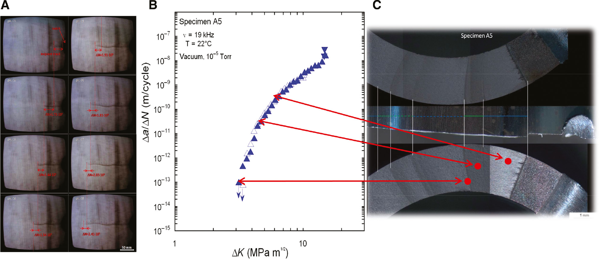
Testing procedure for determination of Δa/ΔN vs. ΔK curves with the ultrasound fatigue technique and correlation with fracture surface morphology. (A) Observation of specimen surface with a microscope attached to a CCD camera, (B) Δa/ΔN vs. ΔK curve, and (C) locations on fracture surfaces are correlated with Δa/ΔN vs. ΔK curve (Stanzl-Tschegg & Schönbauer, 2010b).
The 20-Hz studies with copper were performed with servohydraulic testing equipment under load control. A training procedure was chosen in accordance with former tests (Stanzl-Tschegg & Schönbauer, 2008) for both loading frequencies. The specimens were ramp-loaded in steps of 1 and 5 MPa with a step length of 300 cycles at 20 Hz and 2.1×10⁴ cycles at 19 kHz. The tests were started at a stress amplitude of 10 MPa in the S-N experiments. As no influence of the step height was observed, this task is not considered in the following. For more experimental details, see Stanzl-Tschegg et al. (2007).
If plastic-strain amplitudes are expected to play a role, they have to be determined indirectly by measuring the damping heat with microthermocouples in the ultrasonic tests (Stanzl-Tschegg & Schönbauer, 2007; Stanzl-Tschegg et al., 2007). For these measurements, the temperature rise during one pulse consisting of 1.9×10⁴ cycles or less, e.g. 500 cycles at higher total strain amplitudes (Δεtot/2 above approximately 5×10⁻⁴), is recorded. The accuracy of measurement is 0.01°C, and the statistical error of the plastic strain amplitudes is therefore a few percent. The dissipated energy per cycle ΔW/N can be linked to the plastic strain amplitude Δεpl/2 using the heat capacity c, the mass m, and the temperature change per cycle ΔT/N (Stanzl-Tschegg & Schönbauer, 2007; Stanzl-Tschegg et al., 2007).
The plastic strain amplitudes were determined at both loading frequencies during the training process and also during the S-N tests (Stanzl-Tschegg et al., 2007). During the training procedure at 20 Hz, Δεpl/2 was measured every fifth load step. Beginning with a stress amplitude of 10 MPa, the load was increased in steps of 1 MPa for a defined number of cycles, where the Δεpl/2 remained constant. Then the load was shut-off. The length of every shut-off period, where Δεpl/2 was recorded, was five times the step length used in the S-N tests, namely, 1500 cycles. To obtain data on the evolution of the Δεpl/2 during S-N testing, Δεpl/2 was measured for the highest and lowest stress level tested. Data were recorded automatically by the test and motion software of the servohydraulic machine to calculate Δεpl/2, and single hysteresis loops were used, which can be obtained directly from the machine data, which is in contrast to the ultrasonic-resonance test.
3 Results
3.1 12% Cr steel and 17-4PH steel
The 12% Cr steel was used for studies of environmental influences on the FCG behavior mainly in the VHCF and HCF regimes. The da/dN vs. ΔK curves were determined in vacuum of 10−5 Torr≈10−4 Pa and in air (90°C, 40% RH) as well as in de-aerated 300 ppb Cl− solution and aerated 6 ppm Cl− solution.
Figure 2 (Schönbauer & Stanzl-Tschegg, 2013; Schönbauer et al., 2014) shows the da/dN vs. ΔK curves for three and four different R-ratios. In vacuum, a steadily decreasing ΔK value is obvious at all R-ratios (R=0.05, 0.5, and 0.8), whereas in air, a distinctive threshold between 10−11 and 10−10 m/cycle appears at the three R-ratios. Rather pronounced thresholds also occur in the two tested Cl− solutions. In order to interpret the influences of environment and R-ratio on ΔKth and S-N curve, the following comprehensive experiments were performed.
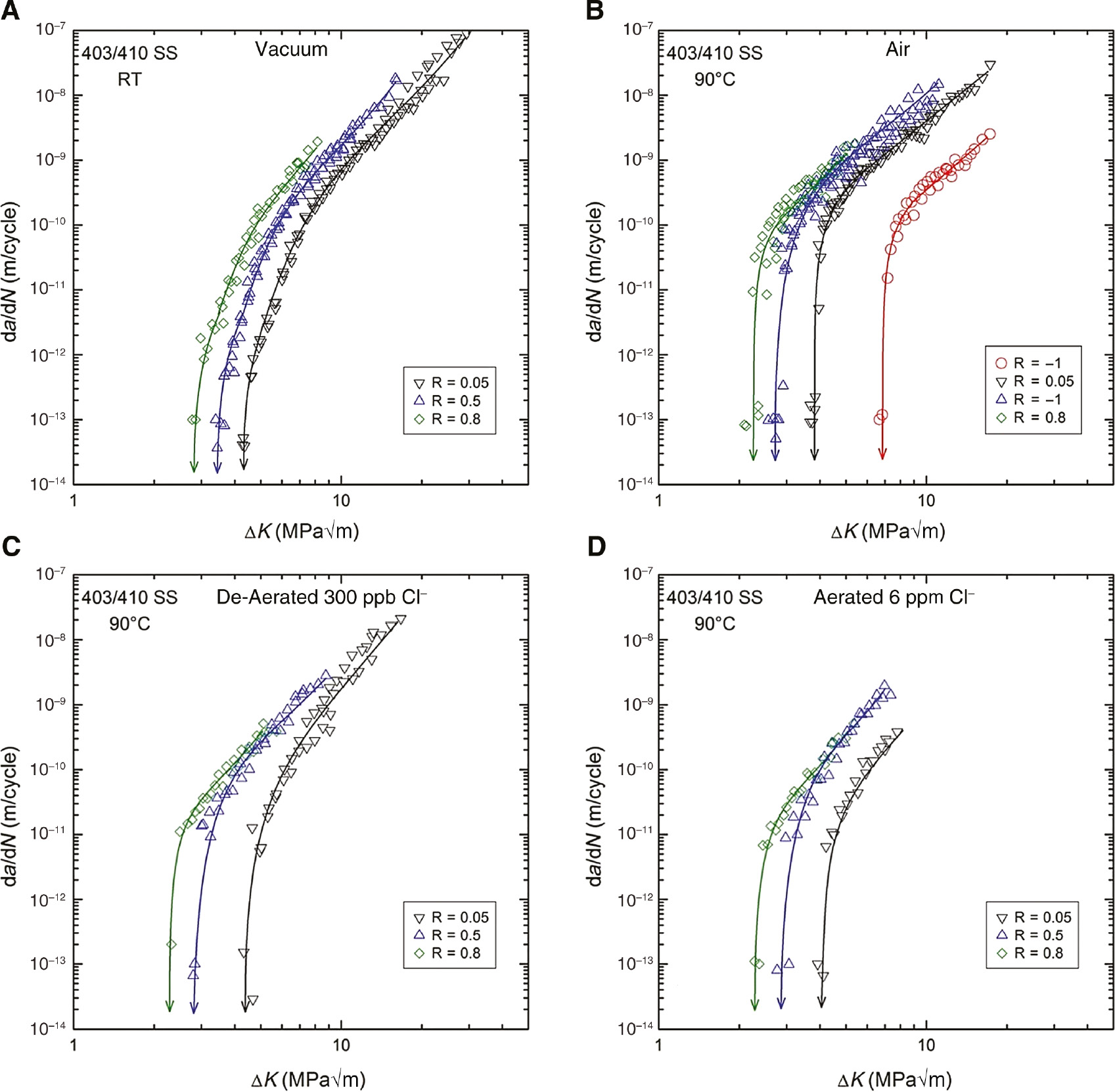
Environmental-assisted FCG curves (Δa/ΔN vs. ΔK) of 12% Cr (AISI 403/410 SS) steel at different R-ratios in (A) vacuum of ≈10−4 Pa, (B) laboratory air (90°C, 40% RH), (C) de-aerated 300 ppb Cl− solution, and (D) aerated 6 ppm Cl− solution. Loading with 20 kHz-ultrasound fatigue technique (Schönbauer & Tschegg, 2013; Schönbauer et al., 2014).
For determining ΔKth, the variation of the R-ratio below a critical value Rc and above was tested in air, in the abovementioned de-aerated and aerated Cl− solutions. For determining S-N curve and Haigh diagram, the variation of the R-ratio was tested at the three mentioned ratios. Variation of the environment was performed at R=0.5 in air and the abovementioned liquids. As result of these experiments, Kitagawa-Takahashi diagrams allowed to determine either the critical ΔKth or the critical pit size for the crack to grow or to arrest at different R-ratios and in different environments.
Additional experiments were performed to study the role of artificial defects by introducing pits with a diameter of 50 μm or alternatively 100 μm. For the experiments at 90°C with R=0.05, the time dependence of fatigue crack formation and elongation from the corrosion pits was investigated (Schönbauer et al., 2015). The main result (Figure 3) is that most of the time is spent for crack initiation and early fatigue crack growth. In Figure 3A, the results for 50 μm pits and in Figure 3B for 100 μm pits are shown, which demonstrates that the higher the Δσ and the larger the pit size is, the higher crack-growth rates result.
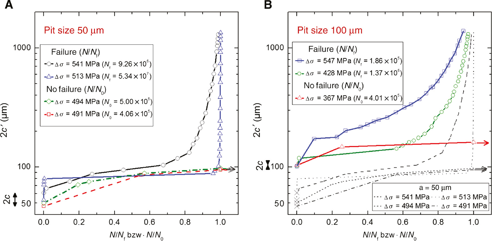
Time dependence of crack formation and elongation from corrosion pits and early FCG in AISI 403/410 steel at 90°C with 20 kHz ultrasound fatigue technique at R=0.05. Pit size. 2c=crack length at the surface including pit, Nf=fatigue life until failure, N0=fatigue life until crack arrest. (A) Initial pit size 50 µm diameter, (B) initial pit size 100 µm. The results of (A) are introduced to demonstrate higher FCG rates for higher Δσ and larger grain sizes (Schönbauer et al., 2015).
With steel 17-4PH, different artificial defects were studied by Schönbauer et al. (2017). Three kinds were used: corrosion pits, drilled holes, and circumferential notches (Figure 4; Schönbauer et al., 2017). Comparison with smooth specimen surfaces showed the following: From smooth surfaces, cracks start from nonmetallic inclusions, failure occurs between 105 and several 1010 cycles, and the existence of an endurance limit is unclear. Evolution of slip-bands and growth of new cracks during the experiment was observed. Contrary to this, crack initiation is completed within 107 cycles in specimens with defects, a fatigue limit exists, and surface as well as interior crack initiation takes place. These observations were enabled by using circumferentially notched specimens.
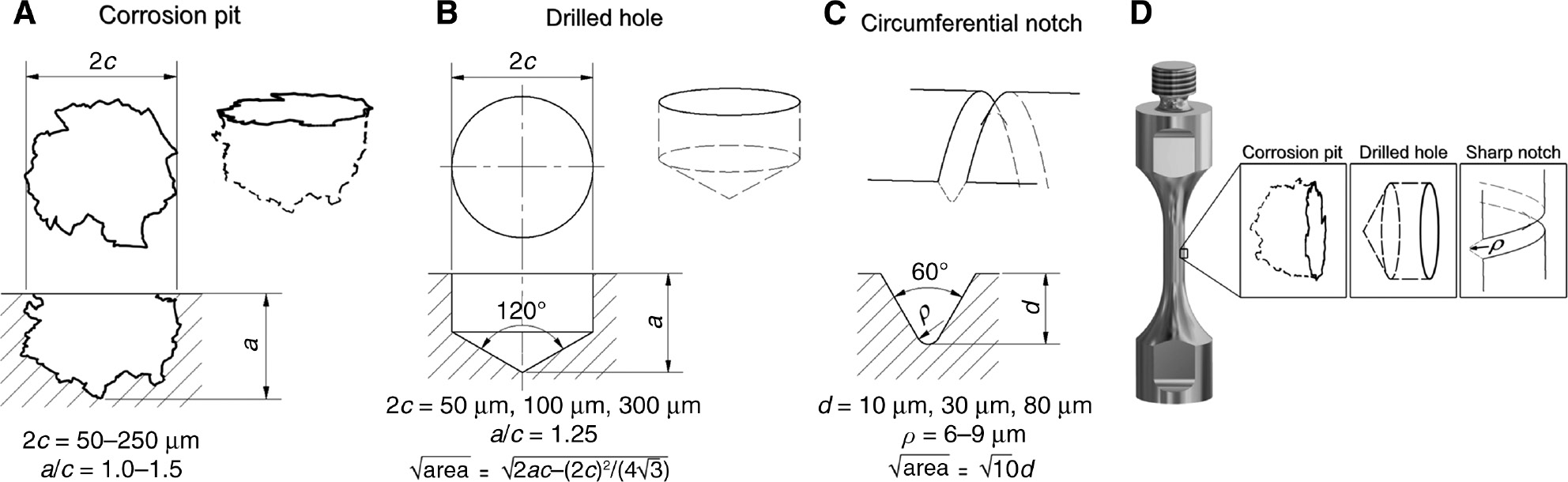
Artificial corrosion pits, drilled holes, and circumferential notches as fatigue-crack starters at 20 kHz ultrasonic loading of 17-4PH steel (Schönbauer et al., 2017). (A) Corrosion pit with irregular pit shape. (B) Drilled hole simulating width and depth of corrosion pit aiming to estimate the effective values of area. (C) Geometry of circumferential notch which leads to similar fatigue limits as corrosion pits. (D) Location of corrosion pit or drilled hole or sharp notch in the specimen.
Calculation of cyclic stress intensity values of pits was performed by assuming that corrosion pits act as stress concentrators. El Haddad et al. (1979) recognized already that not the crack depth but its width is responsible for the growth of a small crack and proposed an empirical relationship (not addressing a physical background). Schönbauer et al. (2015) extended this model for the propagation of small cracks and developed a two-step model for cracks emanating from corrosion pits in 12% Cr steel by implementation of careful fractography with optical microscopy and scanning electron microscopy (SEM; Figure 5). Specimens that had developed an initially invisible small crack aside the pit were further fatigue loaded until a crack on both sides of the pit was seen. It was noticed that up to a defined ratio a/c′ ≥ 0.83 (a=crack depth, c′=half crack width), ΔK remained constant along the whole crack front. It can be calculated as
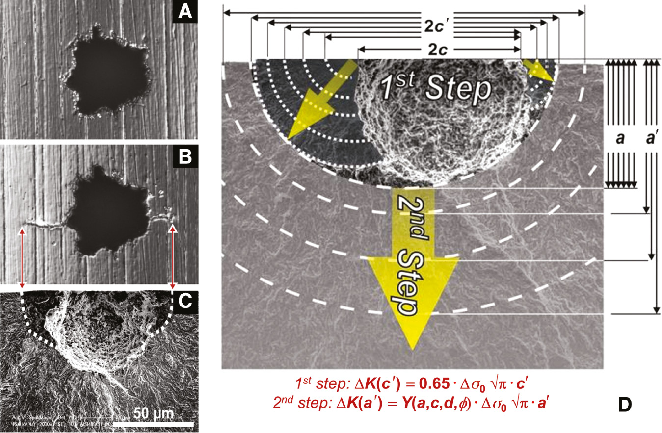
Fracture mechanical evaluation with two-step model (Schönbauer et al., 2014) of small cracks emanating from corrosion pits. (A) Initial corrosion pit, (B) two small cracks observed at specimen surface after≈107 cycles, (C) same area at fracture surface with heat-tinted small cracks, (D) 2-step modeling of small crack growth.
During the second step of crack propagation, the two crack branches form a single crack as soon as a/c′ becomes ≥0.83. Then, ΔK can be calculated according to known literature procedures, e.g. by Newman and Raju (1981) as
The experimental verification of the transition from the first to the second fatigue crack growth step was obtained by a kind of heat tinting, as visible in Figure 5C.
For the three kinds of artificial defects in 17-4PH steel, the limiting fatigue limits for small-crack growth were calculated (Schönbauer et al., 2017), adopting Murakami’s square root area parameter approach (Murakami & Endo, 1983, 1986; Murakami, 2002b). Possible influences of the environment and residual stresses by the machining process were removed by a sophisticated annealing treatment.
S-N and ΔKth data were obtained for R=−1 for different defects in 17-4PH-steel and may be summarized in the following way:
According to Murakami and Endo (1986), the stress range of the fatigue limit Δσw determines the threshold for nonpropagating small cracks by introducing the Vickers hardness HV.
Correlation of Δσw and the threshold stress intensity range ΔKth with linear elastic fracture mechanics (LEFM) principles, introducing HV is restricted to small defects. For larger defects, ΔKth becomes a constant.
The transition of small to long cracks (i.e. to propagation of small cracks) takes place at ΔKth,c=6.7 MPa√m, which means that the critical small-crack length is about 80 μm (several grain diameters).
In Figure 6, the S-N data and ΔKth results are correlated for R=−1 for the three investigated artificial defects of different sizes (Schönbauer et al., 2017). Δσ and ΔKth for specimens containing 50 μm diameter drilled holes lead to the same values as for specimens with a circumferential notch with the same length-√area. Up to a length of approximately 80 μm, nonpropagating small cracks according to Murakami and Endo (1983, 1986) are observed with Δσw values on a line (in the double-logarithmic plot), having a slope of 1:6. Above ≈80 μm, the slope is 1:2. The equations for the lines are indicated in the left image. If the stress-intensity factor range ΔK is plotted versus √area, a slope of 1:3 results, and above ≈80 μm, ΔKth remains constant. In other words, the transition of the slopes takes place at ΔKmax=6.7 MPa√m at √area≈80 μm.
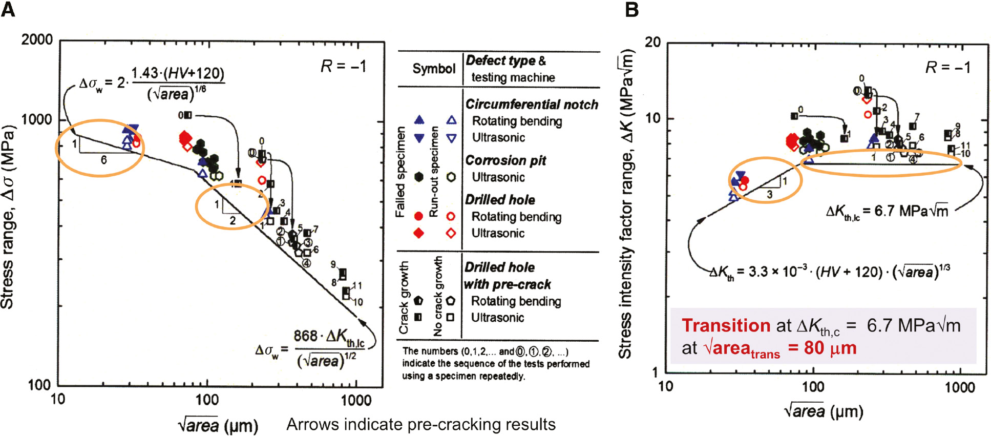
Correlation of S-N data and ΔKth results for three different artificial defects after 20 kHz loading of 17-4PH steel at R=−1 (Schönbauer et al., 2017). (A) At Δσ values up to ≈80 µm, non-propagating small cracks occur according to indicated equation with slope 1:6. Above ≈80 µm, the slope is 1:2. (B) Plotting ΔK instead of Δσ, a slope of 1:3 results at √area ≈80 µm and Δσ remains constant above ≈80 µm.
A similar correlation of S-N data and ΔKth was observed for all studied artificial defects for R=0.05 and 0.4, which means that the critical pit size may be predicted for smooth and prepitted specimens by a Kitagawa-Takahashi approach.
3.2 Aluminum alloy 7075-T651
The main interest was to perform VA-loading experiments with different sequences and superposition of high-frequency and low-frequency loads. The second aim was testing the environmental influences, namely, that of laboratory air and aqueous 3.5% NaCl solution. As summarized in Figure 7, test sequences with constant-amplitude low-frequency (5 or 0.01 Hz) sine and square shape plus superimposed 20 kHz ultrasonic variable-amplitudes were performed (Arcari et al., 2012; Fitzka & Mayer, 2015; Meischel et al., 2016; Stanzl-Tschegg et al., 2016). In the following, only one kind of sequences (Figure 7F) is presented and compared with the results at CA 20 kHz loading.
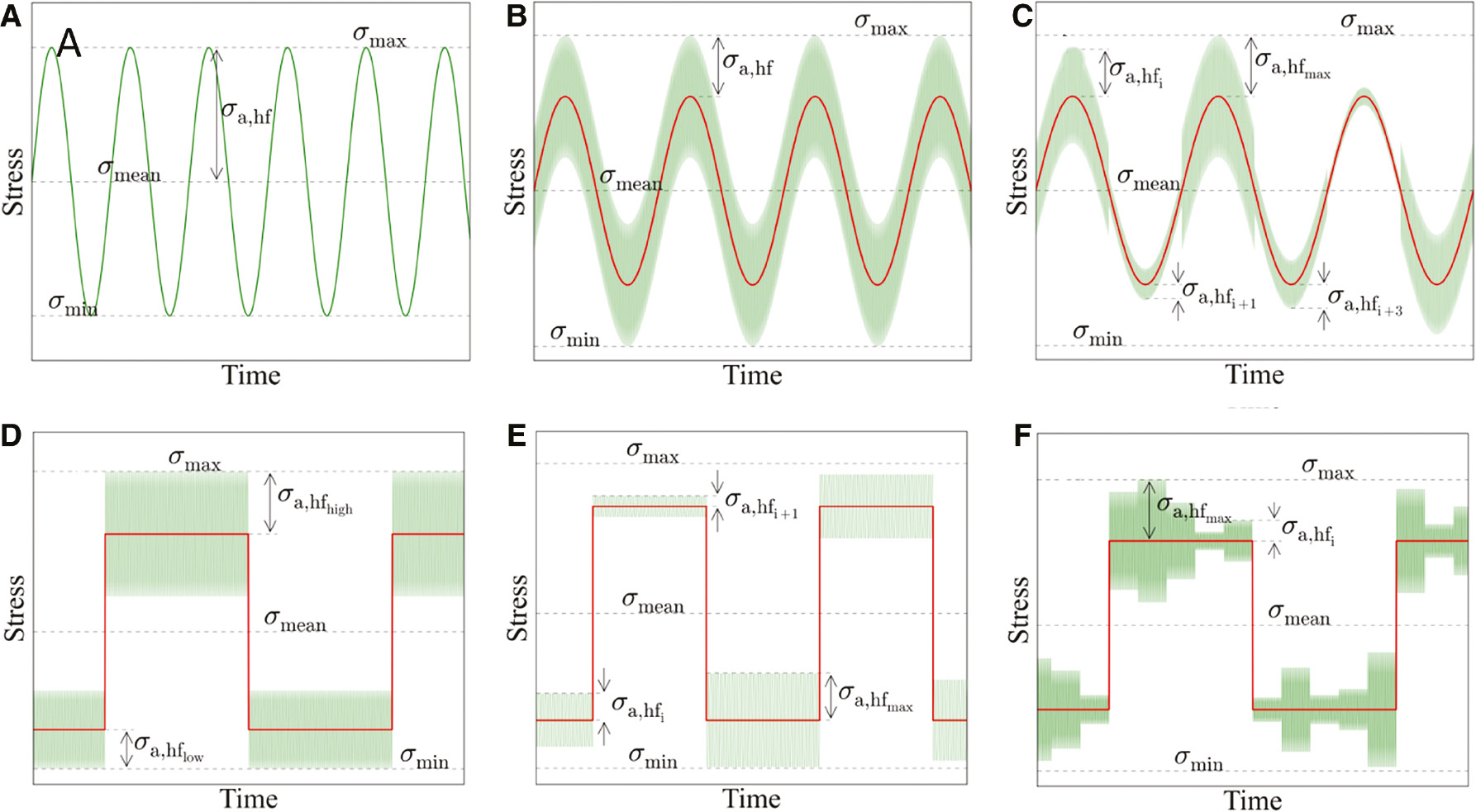
Test sequences with constant-amplitude low-frequency (5 or 0.01 Hz) sine or square shape plus superimposed 20 kHz ultrasonic variable amplitudes. Testing material: 7075-T651 (Fitzka & Mayer, 2015; Meischel et al., 2015). (A) Constant-amplitude 20 kHz sine loading. (B) Constant 20 kHz sine-on constant low-frequency-sine tests. (C) Random 20 kHz-sine-on-constant 5 Hz-sine test. (D) Superposition of changing square 20 kHz blocks on constant low-frequency square carrier waves. (E) Random constant 20 kHz blocks-on constant low-frequency square waves. (F) 5 Random 20 kHz blocks-on constant low-frequency square waves.
For CA-loading with 20 kHz ultrasound in laboratory air, a strong influence of R is observed (Figure 8; Meischel et al., 2015; Stanzl-Tschegg et al., 2016). At R=0.5, the σmax values of the S-N curve are much higher than at R=−1 (Figure 8A). A crack started from an inclusion, the fracture surface is very rough, and crack arrest was noticed after about 109 cycles (Figure 8B). A rough fracture along crystallographic planes and grain boundaries is visible in Figure 8C. The stress amplitude σa was 83 MPa, σmax 330 MPa, σmin 165 MPa, and Nf 2.1×10⁹ cycles (crack propagation was from top of the image). A backscatter SEM image of the same area (Figure 8D) shows the many side cracks in planes other than the main crack plane. This crack growth behavior obviously leads to crack arrest and thus a shift of the S-N curve to much higher stresses. Circled dots in Figure 8A mean that the specimens were further loaded at a higher load after no fracturing took place at the preceding lower load. Numbers aside the symbols characterize the specimen numbers.
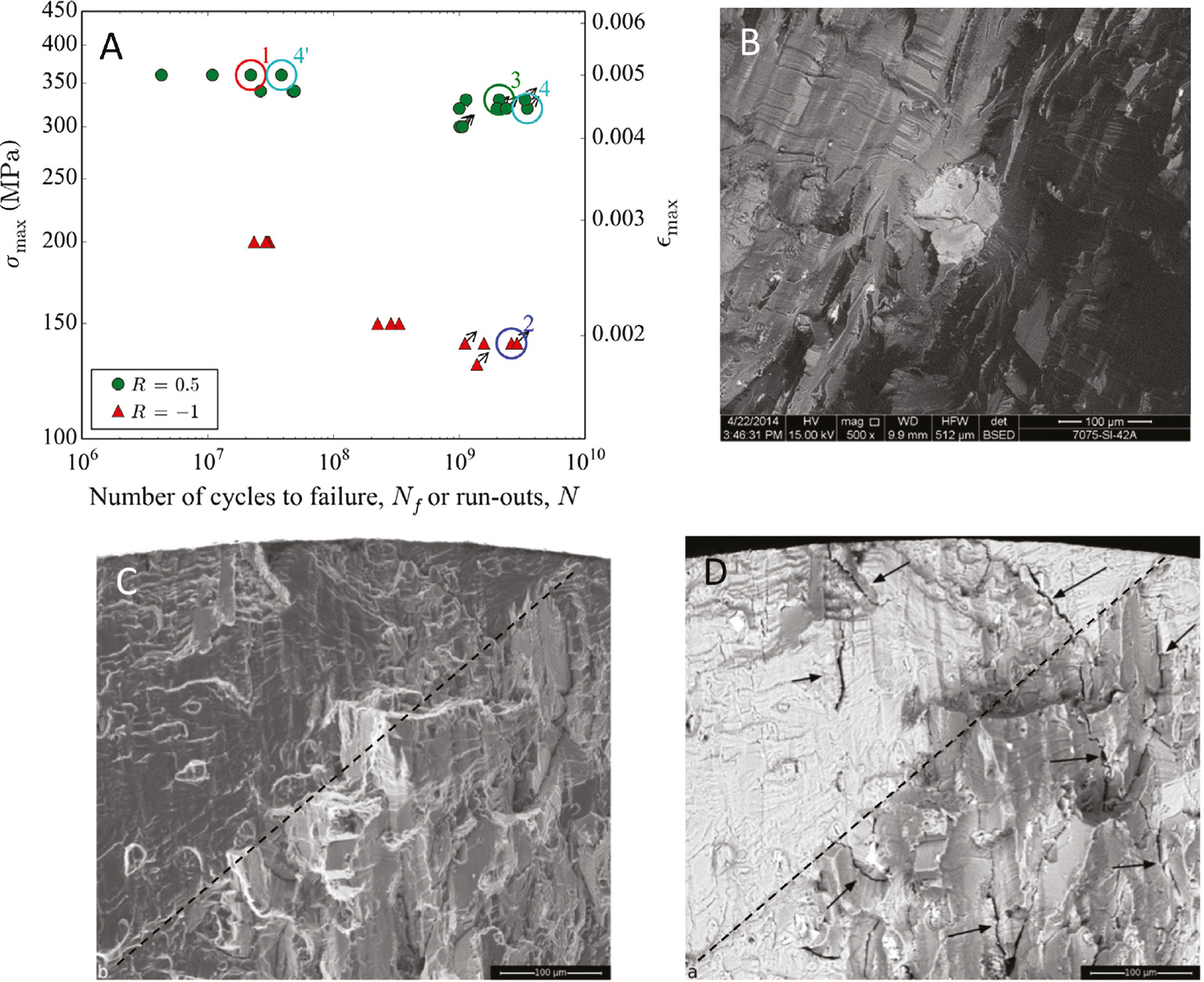
S-N curves of alloy 7075-T651 at constant 20 kHz loading at R=−1 and +0.5 in ambient air and fractography. (A) Strong R-ratio influence. At R=+0.5: (B) interior, brittle crack start from inclusion, crack arrest after 109 cycles. (C) Very rough fracture surface in different planes (border indicated by dashed line) with crystallographic and grain-boundary features. (D) Backscatter (BS) image showing many small side cracks that appeared in other planes than main crack plane (small arrows) (Meischel et al., 2015, Stanzl-Tschegg et al., 2016).
VA results for the indicated sequence at σa,hf=10–20 MPa, σmax=400 MPa, and σmin=20 MPa with different numbers of cycles per block (5000, 4000, and 2000 cycles/block) in laboratory air and 3.5% aqueous NaCl solution (Meischel et al., 2016) as shown in Figure 9 (Stanzl-Tschegg et al., 2016) indicate that the fatigue life is increased in air with increasing number of cycles per block. However, no significant difference of the lifetimes is recognized in the NaCl solution. Fractographic studies revealed the following: in air as well as in NaCl solution, cracks initiated at secondary phase particles at the specimen surface (Figure 9; Stanzl-Tschegg et al., 2016). The loading was random 20 kHz-sine blocks on constant 0.01 Hz-square loads with a block length of 200 ms and 4000 cycles per block and σa,hf=10–70 MPa, σmax=400 MPa, and σmin=20 MPa.
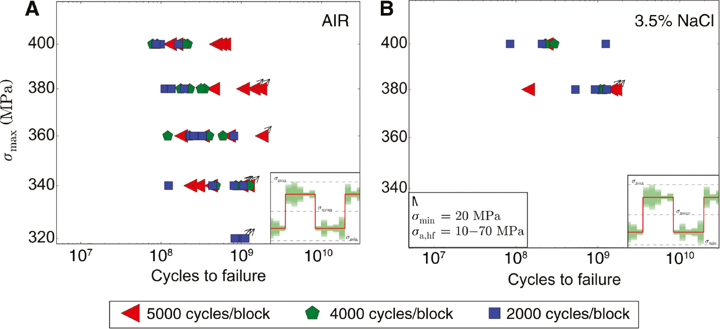
Environmental influence on lifetimes at variable-amplitude (VA) superimposed loading with the indicated sequence (σa,hf=10–20 MPa, σmax=400 MPa, σmin=20 MPa) with three different numbers of cycles/block. (A) In air, fatigue life increases with increasing number of cycles/block, and (B) in 3.5% NaCl solution, no significant influence (Meischel et al., 2016).
Figure 10 shows some more details of the fracture surfaces for loading in air (Nf was 6.14×10⁸ cycles). First, in Figure 10A, bands (made better visible with broken lines) reflect 20 different 20 kHz blocks in a quarter of one low-frequency carrier wave. A closer look (Figure 10B) displays microplasticity features (arrows) of the broken grains and of the crack initiation facet. Even at the tip of a small secondary crack (marked by a rectangular frame), ridges with plastic deformation features are visible. Figure 10C and D come from an experiment with 1 Hz-square plus five superimposed 100 ms long 20 kHz blocks with a maximum stress σmax=320 MPa. As no fracture occurred, the amplitude was increased to σmax=400 MPa, which caused failure after 3.7×10⁷ cycles. The SEM (Figure 10C) shows signs of plastic deformation on a micrometer level in the crack initiation area. With a backscatter view (Figure 10D), the grain on top of the image is identified as a nonmetallic inclusion. It is interesting that even more microplasticity features and small cracks are visible. One small secondary crack (long arrow) has grown by crossing a twin (marked by dashed lines), and plastically deformed areas have formed even within the grain containing the twin. Also less than 10 μm long secondary cracks are visible (small arrows).
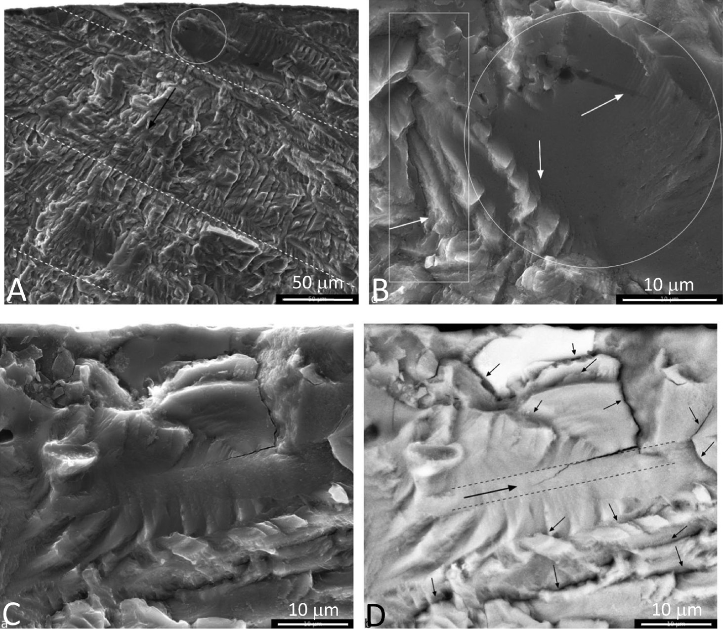
Fractography after random 20 kHz-sine blocks on constant 0.01 Hz-square loads. (A) Bands (broken lines) reflect 20 different 20 kHz blocks in a quarter of one carrier wave. (B) Microplasticity features (arrows) of broken grains and crack initiation facet. (C) Even at a small secondary crack tip (rectangular frame), ridges with plastic deformation features on a micrometer level in the crack initiation area. (D) BS view: microplasticity features and small cracks. Plastically deformed area within grain containing a twin. Shorter than 10 μm long secondary cracks (small arrows; Stanzl-Tschegg et al., 2016).
The fracture surfaces in the NaCl solution compared with air are rougher and more brittle, and deeper cracks appear (Figure 11A, B). VA loading was with block lengths of 200 ms and 4000 cycles/block: σa,hf=10–70 MPa, σmax=400 MPa, σmin=20 MPa, and Nf in air=8.98×10⁷ cycles in 3.5% NaCl solution Nf=2.3×10⁸ cycles. The fractographic features allow interpreting two opposing effects: Rougher fracture surfaces (than in air) with deeper secondary cracks lead to a retardation of crack propagation and probably diminish accelerating effects of corrosion fatigue because of, for example, anodic dissolution of the crack tip.
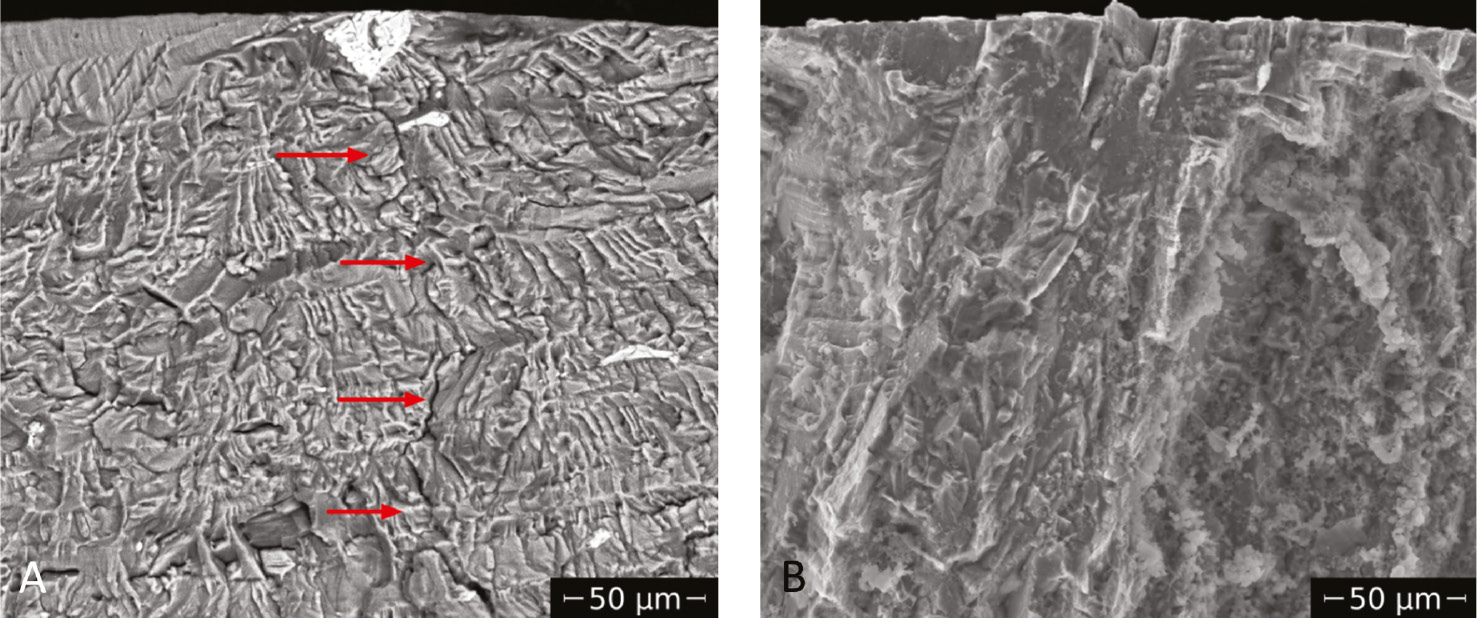
Environmental influence during VA loading (random 20 kHz-sine blocks on constant low-frequency square loads): (B) rougher fracture surfaces of specimen fatigued in 3.5% NaCl with deeper secondary cracks and larger lifetime than after loading (A) in air (shorter life; Meischel et al., 2016).
As a result of all experiments under VA loading in noncorrosive environment, a model is suggested as shown in Figure 12 (Stanzl-Tschegg, 2018). Implementing the corrosive-environmental influences is not tried in this study as it would require considering the numerous mechanisms of corrosive-assisted material response. Main responsible mechanisms favoring FCG of primary cracks under VA loading in contrast to CA loading is the following in the HC and VHCF regime: Numerous repeats of VA sequences favor small (primary) crack growth by producing flatter crack surfaces and less deep secondary cracks due to many periodic overloads. Their number might exceed several 10,000 cycles in the ultrasonic tests. While the rough crack surfaces with deep secondary cracks on planes other than that of the primary crack lead to arrest (see Figure 8B) of the primary small/short crack, such small primary cracks with an initial rate somewhat higher than 1.7×10⁻¹² m/cycle could grow. This means that the primary crack-growth plane is favored and less energy is dispersed in the propagation of several small cracks. From this, an important consequence for practical application of parts and components being loaded in the VHCF regime is the deleterious effect of VA amplitudes. This phenomenon has not been detected up to now, as the time-saving ultrasound fatigue technique is needed for this and has not been used until recently.
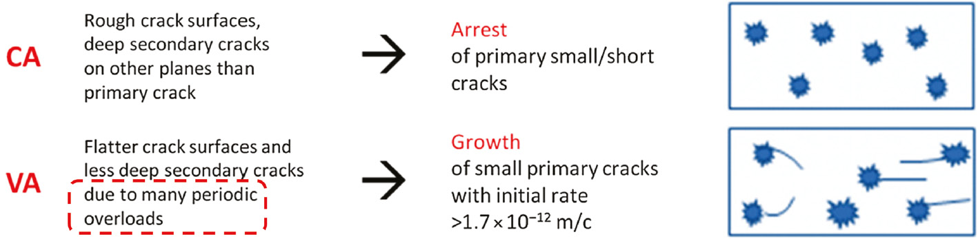
Interpretation and model for deleterious effect of high and very high numbers of cycles during variable-amplitude loading, without considering environmental effects. Numerous periodic overloads lead to smoother crack surfaces and less deep secondary cracks than at CA loading so that small primary cracks can grow easier (Stanzl-Tschegg et al., 2016).
3.3 Polycrystalline copper
The homogeneous and high-ductile material copper is another material that shifts the S-N curve toward much higher cyclic total-strain and stress amplitudes in comparison to the threshold small-crack formation (Figure 13; Stanzl-Tschegg & Schönbauer, 2007, 2014). The endurance limit after more than 1011 cycles is observed at a stress amplitude Δσ/2=93 MPa and PSB formation at values Δσ/2 between 47 and 63 MPa. Even after complete coverage of the specimen surface with PSBs, no crack initiation was discovered. The specimen surfaces look quite similar slightly below the stress amplitudes of the endurance curve (Δσ/2=93 MPa), and the PSB-threshold loading at amplitudes between 47 and 63 MPa after N is between 106 and several 1010 cycles, which is shown in Figure 13B and C. This indicates that short cracks or intrusions with lengths between 20 and 40 μm do not grow in the stress amplitude range of 47 to 93 MPa, even if more than 1011 cycles are applied.
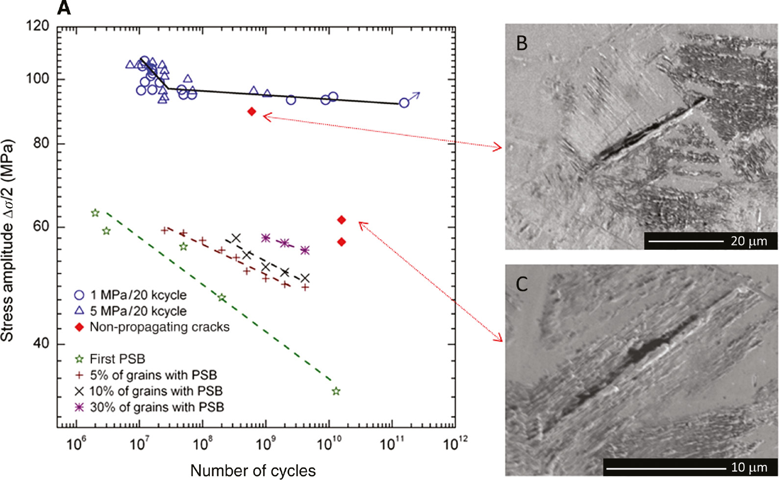
S-N diagram and PSB threshold of electrolytic copper. (A) Endurance limit Δσ/2=93 MPa after more than 1011 cycles; PSB formation at Δσ/2 between 47 and 63 MPa. (B) No short crack or intrusion transition to a long crack after loading (C) with Δσ/2 between 47 and 63 MPa and (B) between 63 and 93 MPa (Stanzl-Tschegg & Schönbauer, 2007, 2014).
ECC/FE and In-Lens SE detector studies with SEM showed that not only small surface but also interior cracks had been formed at and even below the PSB threshold. Δσ/2 was ≤54 MPa after N=1.59×10¹⁰ cycles in Figure 14A and ≤61.5 MPa in Figure 14B (Stanzl-Tschegg et al., 2011). Even high-purity 99.999% specimens of identical shape, grain size, and same loading conditions showed small stage I-internal and surface cracks, which had a length of typically 20 μm and did not propagate while fracturing took place apart from these at another place of the specimen, which was loaded with the same amplitude (Weidner et al., 2010).
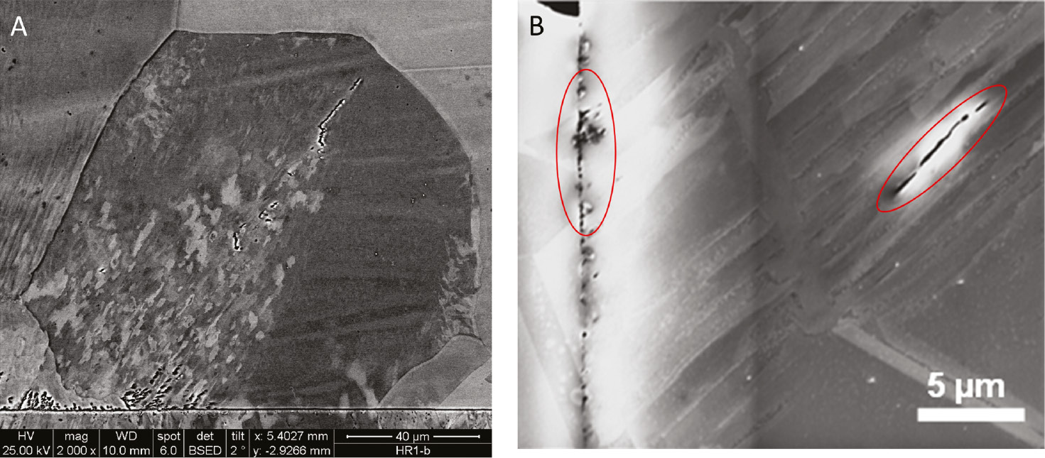
Formation of very small surface and interior cracks formed at and below PSB threshold. (A) Interior small crack about 80 μm away from surface and simultaneously formed small surface cracks. (B) Magnified view of surface and interior small cracks in electrolyte copper (Weidner et al., 2010; Stanzl-Tschegg et al., 2011).
Usage of a Kitagawa evaluation of S-N and FCG data (Stanzl-Tschegg & Schönbauer, 2010b) together with evaluation of crack lengths on the specimen surfaces at defined loading conditions (19 kHz ultrasonic fatigue) revealed the following results (Figure 15): Formation of long propagating fatigue cracks is possible if stress amplitudes Δσ (for this plot loading at R=−1 was presumed) above Δσ ≥ 93 MPa are provided either by the external load or a notch so that a crack length ≥340 μm can be produced. At Δσ between 63 and 93 MPa, many small cracks with a length between 20 and 340 μm are generated, and at Δσ between 63 and 45 MPa, few small cracks with lengths between 20 and 50 μm are formed. The figure shows that a modification of theoretical prediction according to experimental experience is useful.
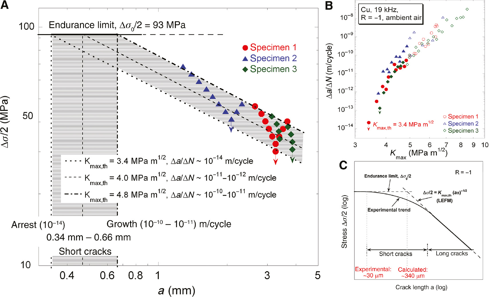
Kitagawa and S-N data. (A) Δσ≥93 MPa are needed so that a crack of ≥340 μm is growing. At Δσ=63–93 MPa, many cracks with a length of 20–340 μm are formed, and at Δσ=45–63 MPa few small cracks with lengths of 20–50 μm are generated which do not propagate. (B) Measured Δa/ΔN vs. Kmax curves and ΔKth values. (C) Kitagawa plot with experimental and calculated (on the basis of LEFM) short-crack regimes (Stanzl-Tschegg & Schönbauer, 2010b).
Figure 16 provides a flow chart of the observed mechanisms leading to specified dislocation arrangements prior to small-crack formation, leading to growth and arrest of small cracks at specified stress amplitudes as defined in the S-N diagram in Figure 13 and the conditions that enable the development of small cracks into a long crack.
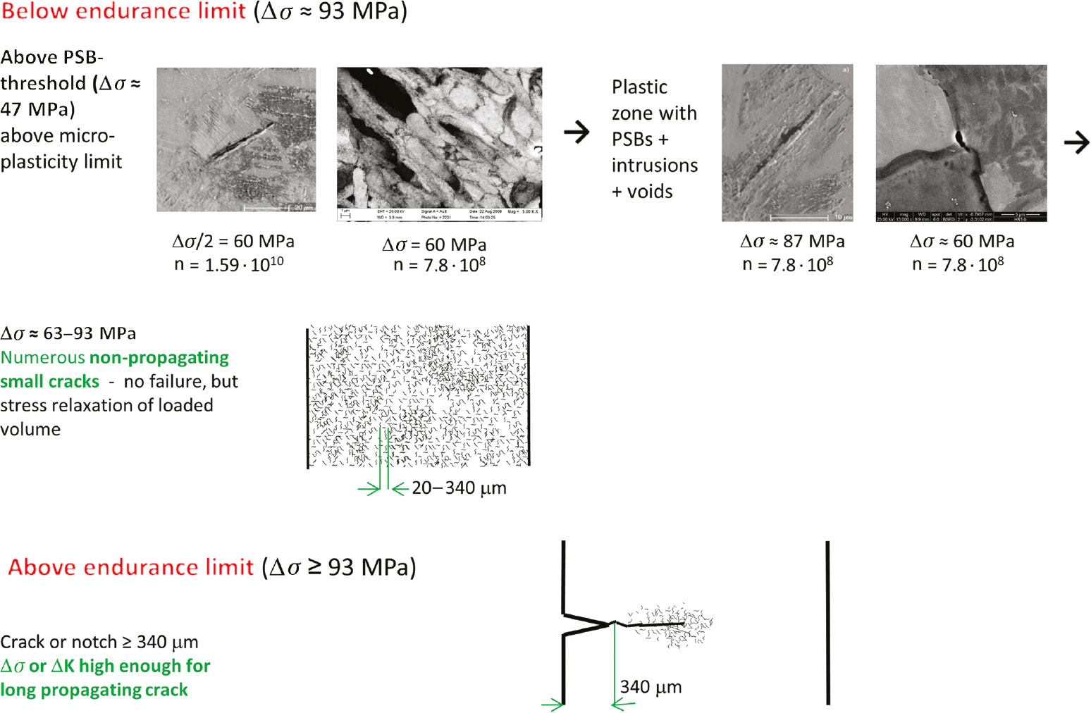
Flow diagram of mechanisms causing PSB, small and long crack formation, and propagation or arrest at specified stress amplitudes.
4 Discussion
Trying to answer the question about propagation or arrest of small cracks, various parameters have been considered, and based on the results, following answers may be given. For many metallic materials, such as steels, Al alloys, and polycrystalline copper, threshold values of load or cyclic stress intensity factor as well as defect size determine mainly the small to long crack transition. This seems to be common for all investigated materials, though of course the absolute values of the mentioned thresholds are different. Besides the discussed mechanisms, the environment plays a dominant role for the material response.
The limiting values (mechanical and structural thresholds) may be characterized on different scales of magnification ranging from macroscopic (typically millimeters) to even atomistic dimensions. For the tested steels, the role of defects being inclusions, grain boundaries with different size and orientation, or corrosion pits on specimen surfaces in the micrometer range were shown to determine growth or arrest of small cracks. But the role of micro-microstructure can be traced even into the micrometer range via, for example, fatigue striations, dislocation pile-ups at grain boundaries, and furthermore to atomistic values by considering dislocation emission and movement. A model differentiating between small and long crack growth behavior was developed, where some of the observations in the millimeter and micrometer range were implicated (Figure 5).
With 17-4 PH steel, a specific critical defect size of about 80 μm could be detected, which determines the critical stress range Δσc for fatigue crack growth (fatigue limit), as demonstrated by Schönbauer et al. (2017). Below this defect size of ≈80 μm (and Δσc), ΔKth increases and is constant above (the √area length of ≈80 μm covers several grain sizes). Correlation of Δσc and ΔKth and using a Kitagawa-Takahashi approach determines the criterion for the transition of a small to a long crack. The surface roughness is another macroscopic feature playing a role for growth or arrest of small cracks. Removing drilled holes or scratches from a specimen surface showed this (after a careful heat-treatment was applied to remove residual stresses of drilled holes).
Another kind of “macroscopic” defects that cause crack arrest of small cracks are such small cracks that are formed in other than that of primarily created cracks. Their effectiveness is caused – among other influences – by the material’s microstructure, i.e. by “microscopic” features. This effect was observed for VA loading of the Al alloy 7075-T651 in the HCF and VHCF regime in laboratory air (Figure 11; Stanzl-Tschegg et al., 2016). The result is in contrast to CA loading and is most probably caused by the high number of the repeats of the VA sequences in the VHCF regime (several 10,000 repeats, made possible by the ultrasonic fatigue-testing technique). The high number of periodic higher overloads and underloads during each VA sequence produces flatter crack surfaces with less deep secondary cracks. Consequently the already existing primary cracks are favored to grow. This contrasts the arrest of primary small cracks at CA loading because of the formation of very rough crack surfaces caused by deep secondary cracks on other than the primary crack growth plane. This VA result leads to the most important consequence for practical purposes that high and very high numbers of cycles have a deleterious effect. A similar deleterious effect has to be expected for single overloads or underloads. Recently, Ogawa et al. (2018) could demonstrate that hydrogen precharging reduces the fatigue strength in the VHCF regime at VA loading of bearing steels.
Considering polycrystalline copper as a so-called homogenous material containing no large inclusions or other defects of similar size allows studies down to the micrometer and nanometer scales. As explained in Figure 16, specified dislocation arrangements such as PSBs with a typical ladder structure, intrusions, and voids in the range of a few micrometer diameter are sufficient to enable the formation of a long crack. In other words, the endurance limit is much higher than the stress amplitude, which is needed to form PSBs and small cracks (Figure 12; Stanzl-Tschegg & Schönbauer, 2010b). In order to obtain failure by driving a long crack, a stress amplitude approximately twice as high as that to form “plastic” or “micro-plastic” features such as PSBs, intrusions, and extrusions is required. This is reached by a high enough external load or by stress concentrations induced by (sharp enough) precracks or notches (Figure 15). These considerations are used to try and understand the mechanisms of small-crack growth and demonstrate that they are produced on different scales of magnification, which are summarized in Figures 12 and 16. Warner (2018) pointed likewise to an atomistic treatment of fatigue cracks emanating from material defects such as corrosion pits.
Implementing the impact of environment (e.g. corrosion fatigue, stress-corrosion cracking, and hydrogen embrittlement) in a general way is not possible owing to the many different and partly opposing mechanisms (accelerating or retarding fatigue crack growth rates). Among these, transport mechanisms of liquid or gaseous parts play a role. In the crack-tip region gas-phase transport, physical adsorption, dissociative chemical adsorption, hydrogen entry, and diffusion as well as embrittlement in the fracture zone take place (Wei, 1970; Gangloff & Wei, 1978). On an already formed crack, oxide layers may be built up. In aqueous solutions and probably also gaseous environment, electrochemical processes such as dissolution of metal at the crack tip, hydrolysis of metal ions in the solution, and hydrogen discharge as well as hydrogen embrittlement and interaction between crack tip and crack flanks are mechanisms that accelerate the fatigue crack growth rates (Rhodes, 1969). FCG-retarding mechanisms are crack-tip blunting, usually the formation of an oxide film, which passivates freshly formed crack surfaces, as well as crack-closure effects, being mainly oxide- and roughness-induced closure.
Accelerating or retarding mechanisms may act independently or may depend on the loading frequency as was demonstrated in experiments on 12% Cr steel in demineralized water at 5 Hz and 20 kHz loading frequency. In the stress-intensity threshold regime below about 10−9 m/cycle, a negligible frequency effect was detected, which was indicating true corrosion fatigue. Above this range (ΔK>7.5 MPa√m), increasing fatigue crack growth rates with decreasing loading frequency were noticed and interpreted as static stress corrosion cracking superimposed to corrosion fatigue (Schönbauer & Stanzl-Tschegg, 2012).
Owing to the high variety of manifold environmental influences, it is assumed that material properties and exact environmental conditions have to be identified for each case to allow any prediction. Probably only experimental studies can provide reliable results. This seems to be especially necessary for VHCF cases.
5 Summary and outlook
Results published for three groups of metallic materials (steels, Al-alloys, and copper) are presented, and their response to different loading conditions in different environments on formation, propagation, or arrest of small cracks and transition to final failure by long-crack propagation are discussed. The mechanisms were studied on various scales of magnification, ranging from optical-microscopic (mm) down to a submicroscopic regime of a few micrometers into the nanometer range. The following results were obtained, and models for their interpretation are presented:
The development (growth or arrest) of small cracks into a long crack is driven by several competing processes (due to material, way of loading, environment, etc.).
Growth of small cracks takes place in mainly two steps for all tested materials and can be characterized by cyclic-stress amplitude values in the first step and by cyclic-stress intensities in the second step.
The environment plays a predominant role.
Especially in the high cycle and very high cycle regime, the complexity of interacting processes needs further – mainly experimental – investigations.
The following studies are planned:
Tests on other materials, such as Ti alloys, different Al and Mg alloys and additive manufactured materials.
Experiments in high vacuum and in various aqueous Cl− solutions.
Variable-amplitude loading with various sequences, superimposed single overloads, underloads, periodic pauses, and different testing frequencies.
Use of the time-saving ultrasonic fatigue technique for research in the VHCF regime will be indispensable.
Abbreviations
- a
-
crack depth, pit depth
- √area
-
square root of projection area of inclusion or defect (μm)
- BOKU
-
University of Natural Resources and Life Sciences, BOKU, Universität für Bodenkultur Vienna, Austria
- c′
-
half crack width
- CA
-
constant amplitude
- CCD camera
-
charge-coupled device camera
- da/dN vs. ΔK
-
fatigue crack growth rate versus cyclic stress intensity factor range
- EBSD
-
electron backscatter diffraction
- ECC/FE
-
electron channeling contrast in scanning-electron microscope with field emission gun
- FCG
-
fatigue crack growth
- FGA
-
fine granular area
- FCGRs
-
fatigue crack growth rates
- GBF
-
granular bright facet
- HCF
-
high cycle fatigue
- HEAC
-
hydrogen environment-assisted cracking
- HV
-
Vickers hardness
- In-lens SE detector
-
special scanning electron microscope detector
- K
-
cyclic stress intensity factor
- ΔK
-
cyclic stress intensity factor range
- K max
-
upper limit of stress intensity factor range
- ΔKth
-
threshold stress intensity factor range
- LEFM
-
linear elastic fracture mechanics
- NASGRO
-
fracture mechanics and FCG software for applications for aircraft, spacecraft, rotorcraft, gas
- N f
-
number of cycles to failure
- ODA
-
optically dark area
- ppb
-
parts per billion
- ppm
-
parts per million
- R
-
stress ratio, σmin/σmax
- RH
-
relative humidity
- SEM
-
scanning electron microscope
- SiC
-
silicon carbide
- SIF
-
stress-intensity factor
- S-N
-
stress-cycle diagram, Wöhler curve
- SUJ2 steel
-
Japanese high-carbon chromium steel
- TEM
-
transmission electron microscope
- VA
-
variable amplitude
- ΔT/N
-
temperature change per cycle
- VHCF
-
very high cycle fatigue
- ΔW/N
-
dissipated energy per cycle
- Y(a, c, d, Φ)
-
Y boundary correction factor of crack depth a, half crack length c, specimen diameter d, and geometry factor of semi-elliptical crack Φ
- Δεtot/2
-
total strain amplitude
- Δεpl/2
-
plastic strain amplitude
- ΔσH
-
upper limit of cyclic stress range
- ΔσL
-
lower limit of cyclic stress range
- Δσ0
-
fatigue limit of smooth specimen
- σ a,hf
-
stress amplitude of high-frequency (20 kHz) load
- σ max
-
maximum of stress amplitude of high frequency load
- σ mean
-
mean stress of VA high-frequency load superimposed to low-frequency CA load
- σ min
-
minimum of stress amplitude of high-frequency load
- Δσc
-
critical stress range for fatigue crack growth (transition short to long crack) in Kitagawa-Takahashi-El Haddad diagram
- Δσw
-
fatigue limit of smooth specimen
Acknowledgments
The author wants to thank Profs. Ronald Latanision, Asuri Vasudevan, James Burns, Henry Holroyd, and their organization teams. Thanks also go to my former cooperation partners and friends, Profs. Nagaraja Iyyer and Alan Turnbull. Likewise I want to thank my colleagues and former students at BOKU University for their manifold input to enable the reported results, especially Drs. Bernd Schönbauer, Martin Meischel, and Michael Fitzka.
References
Alderliesten R, Brunner AJ, Pascoe JA. Cyclic fatigue fracture of composites: what has testing revealed about physics of the progresses so far? Eng Fract Mech 2018; 203: 186–196.10.1016/j.engfracmech.2018.06.023Suche in Google Scholar
Amiri M. A continuum mechanics model for fatigue life prediction with pre-corrosion and sequential corrosion fatigue. In: Vasudevan AK, Holroyd H, Latanision R, editors. ECI Engineering Conferences International, Stress-Assisted Corrosion Damage V, session VII, Hernstein, Austria, July 15–20, 2018.Suche in Google Scholar
Arcari A, Tschegg S, Meischel M, Apetre N, Iyyer N, Kang P. Influence of superimposed VHCF loadings in cyclic fatigue of 7075-T6 aluminium alloy. American Institute of Aeronautics and Astronautics Paper 2012; 1732: 1–11.10.2514/6.2012-1732Suche in Google Scholar
Arcieri EV, Baragetti S, Borzini E. Transition from small to large cracks in Ti-6Al-4V specimens. In: Vasudevan AK, Holroyd H, Latanision R, editors. ECI Engineering Conferences International, Stress-Assisted Corrosion Damage V, session VII, Hernstein, Austria, July 15–20, 2018.Suche in Google Scholar
Asami K, Sugiyama Y. Fatigue strength of various surface hardened steels. J Heat Treatment Technol Assoc 1985; 5: 147–150.Suche in Google Scholar
Burns JT, Bush RW, Ai JH, Jones JL, Lee Y, Gangloff RP. Effect of water vapor pressure on fatigue crack growth in Al-Zn-Cu-Mg over wide-range stress intensity factor loading. Eng Fract Mech 2015; 13: 34–55.10.1016/j.engfracmech.2014.11.009Suche in Google Scholar
Castelluci GM, McDowell DL. Microstructure and mesh sensitivities of mesoscale surrogate driving force measures for transgranular fatigue cracks in polycrystals. Mater Sci Eng A 2015; 639: 626–639.10.1016/j.msea.2015.05.048Suche in Google Scholar
Co NE, Brown D, Burns J. Understanding corrosion features and alloy microstructural effects on fatigue crack initiation of corroded AA7050-T7451 using data science. In: Vasudevan AK, Holroyd H, Latanision R, editors. ECI Engineering Conferences International, Stress-Assisted Corrosion Damage V, session VII, Hernstein, Austria, July 15–20, 2018.Suche in Google Scholar
Chowdhury P, Senitoglu N. Mechanisms of fatigue crack growth – a critical digest of theoretical developments. Fatigue Fract Eng Mater Struct 2016; 39: 652–674.10.1111/ffe.12392Suche in Google Scholar
Christ HJ. Cyclic stress-strain response and microstructure. In: Fatigue and fracture. ASM Handbook. Materials Park, OH: ASM International, 1996; 19: 73–95.10.31399/asm.hb.v19.a0002354Suche in Google Scholar
Easter N. Understanding corrosion features and alloy microstructure effects on fatigue initiation of corroded AA7050-T7451 using data science. In: Vasudevan AK, Holroyd H, Latanision R, editors. ECI Engineering Conferences International, Stress-Assisted Corrosion Damage V, session VII, Hernstein, Austria, July 15–20, 2018.Suche in Google Scholar
El Haddad MH, Topper TH, Smith KN. Prediction of nonpropagating cracks. Eng Fract Mech 1979; 11: 573–584.10.1016/0013-7944(79)90081-XSuche in Google Scholar
Fitzka M, Mayer H. Constant and variable amplitude fatigue testing of aluminum alloy 2024-T351 with ultrasonic and servo-hydraulic equipment. Int J Fatigue 2015; 91: 363–372.10.1016/j.ijfatigue.2015.08.017Suche in Google Scholar
Furuya Y. Notable size effects on very high cycle fatigue properties of high-strength steel. Mater Sci Eng A 2011; 528: 5234–5240.10.1016/j.msea.2011.03.082Suche in Google Scholar
Furuya Y, Matsuoka S, Abe T, Yamaguchi K. Gigacycle fatigue properties for high-strength low-alloy steel at 100 Hz, 600 Hz, and 20 kHz. Scr Mater 2002; 46: 157–162.10.1016/S1359-6462(01)01213-1Suche in Google Scholar
Furuya Y, Hiukawa H, Kimura T, Hayaishi M. Gigacycle fatigue properties of high-strength steels according to inclusion and ODA sizes. Metall Mater Trans A 2007; 38A: 1722–1730.10.1007/s11661-007-9225-3Suche in Google Scholar
Gallager JP, Giessler FJ, Berens AP, Engle RM. Damage tolerance design handbook: guidelines for the analysis and design of damage-tolerant aircraft AFWAL-TR-82-3073. Air Force Research Laboratory, Wright-Patterson Air Force Base, USA, 1985.Suche in Google Scholar
Gangloff RP, Wei RP. Fractography in failure analysis. In: Strauss BM, Cullen WH, editors. ASTM STP645. Materials Park, OH: ASTM International, 1978; 87–106.10.1520/STP38087SSuche in Google Scholar
Gates N, Fatemi A. Friction and roughness induced closure effects on shear-mode crack growth and branching mechanisms. Int J Fatigue 2016; 92: 442–458.10.1016/j.ijfatigue.2016.01.023Suche in Google Scholar
Genet M, Couégnat G, Tomsia AP, Ritchie RO. Scaling strength distributions in quasi-brittle materials from micro- to macro-scales: a computational approach to modelling nature-inspired structural ceramics. J Mech Phys Solids 2014; 68: 93–106.10.1016/j.jmps.2014.03.011Suche in Google Scholar
Harris ZD, Burns JT. Elucidating the mechanistic influence of strengthening precipitate morphology on hydrogen environment-assisted cracking in a Ni-Cu superalloy. In: Vasudevan AK, Holroyd H, Latanision R, editors. ECI Engineering Conferences International, Stress-Assisted Corrosion Damage V, session IV, Hernstein, Austria, July 15–20, 2018.Suche in Google Scholar
Heinz S, Balle F, Wagner G, Eifler D. Innovative Ultraschall-Prüfeinrichtung für Ermüdungsversuche im VHCF-Bereich. Mater Test 2012; 54: 11–12.10.3139/120.110395Suche in Google Scholar
Holroyd H. Extraction of EAC crack growth rates and stress intensity factors from slow strain rate tests data for 5XXX and 7XXX series aluminum alloys. In: Vasudevan AK, Holroyd H, Latanision R, editors. ECI Engineering Conferences International, Stress-Assisted Corrosion Damage V, Hernstein, Austria, July 15–20, 2018.Suche in Google Scholar
Holroyd NJH, Vasudevan AK, Christodoulou L. Stress corrosion of high-strength aluminum alloys. Treatise Mater Sci Technol 1989; 31: 463–483.10.1016/B978-0-12-341831-9.50021-8Suche in Google Scholar
Hu Y, Sun C, Hong Y. Crack growth rates and microstructure feature of initiation region for very-high-cycle fatigue of high-strength steel. Fatigue Fract Eng Mater Struct 2018; 41: 1–16.10.1111/ffe.12811Suche in Google Scholar
Huang P, Peng D, Jones R. The USAF characteristic K approach for cracks growing from small material discontinuities under combat aircraft and civil aircraft load spectra. Eng Fail Anal 2017; 80: 39–48.10.1016/j.engfailanal.2017.03.008Suche in Google Scholar
Iyyer N. A continuum mechanics model for fatigue life prediction with pre-corrosion and sequential corrosion fatigue. In: Vasudevan AK, Holroyd H, Latanision R, editors. July 15–20, 2018, Hernstein, Austria; ECI Engineering Conferences International, Stress-Assisted Corrosion Damage V, session VII.Suche in Google Scholar
Jordon JB, Gibson JB, Horstemeyer MF, El Kadiri H, Baird JC, Luo AA. Effect of twinning, slip, and inclusions on fatigue anisotropy of extrusion-textured AZ61 magnesium alloy. Mater Sci Eng A 2011; 528: 6860–6871.10.1016/j.msea.2011.05.047Suche in Google Scholar
Kameda J. Ductile-brittle transition temperature shift controlled by grain boundary decohesion and thermally activated energy and hydrogen GB embrittlement. In: Vasudevan AK, Holroyd H, Latanision R, editors. ECI Engineering Conferences International, Stress-Assisted Corrosion Damage V, session IV, July 15–20, 2018, Hernstein, Austria.Suche in Google Scholar
Kim H, Mitton DB, Latanision RM. Corrosion behavior of Ni-base alloys in aqueous HCl solution of pH2 at high temperature and pressure. Corros Sci 2010; 52: 801.10.1016/j.corsci.2009.10.042Suche in Google Scholar
Krupp U. Structural loading of cellular metals and standardization concepts. Mater Sci Forum 2018; 933: 220–225.10.4028/www.scientific.net/MSF.933.220Suche in Google Scholar
Krupp U, Düber O, Christ HJ, Schick A, Fritzen CP. Application of the EBSD technique to describe the initiation and growth behaviour of microstructurally short fatigue cracks in a duplex steel. J Microsc 2004; 213: 313–320.10.1111/j.0022-2720.2004.01306.xSuche in Google Scholar
Lampman SR, Davidson GM, Reidenbach F, Boring RL, Hammel A, Henry SD, Scott Jr WW, editors. ASM handbook: fatigue and fracture. Materials Park, OH: ASM International, 1996.Suche in Google Scholar
Latanision R, editor. ECI Engineering Conferences International, Stress-Assisted Corrosion Damage, July 15–20, 2018, Hernstein, Austria.Suche in Google Scholar
Lei WS. A generalized weakest-link model for size effect on quasi-brittle materials. J Mater Sci 2018; Doi 1007/s10853-017-1574-8.1007/s10853-017-1574-8Suche in Google Scholar
Li Z, Wang Q, Luo AA, Dai J, Zou H, Peng L. Effect of heat treatment on strain-controlled fatigue behavior of cast Mg-Nd-Zn-Zr alloy. J Mater Sci Technol 2018; 34: 2091–2099.10.1016/j.jmst.2018.05.001Suche in Google Scholar
Lua J, Pham DC, Sadeghirad A, Karuppiah A, Cui X, Seneviratne W, Phan ND. Characterization and fabrication induced defects and assessment of their effects on integrity of composite structures. AHS International 74th Annual Forum & Technology Display, Phoenix, Arizona, USA, May 14–17, 2018.Suche in Google Scholar
Lynch S. Some fractographic contributions to understanding fatigue crack growth. Int J Fatigue 2017; 104: 12–28.10.1016/j.ijfatigue.2017.06.036Suche in Google Scholar
Lynch S. Recommendations and rants regarding research on environmentally assisted cracking. In: Vasudevan AK, Holroyd H, Latanision R, editors. ECI Engineering Conferences International, Stress-Assisted Corrosion Damage V, July 15–20, 2018, Hernstein, Austria.Suche in Google Scholar
Mayer H. Recent developments in ultrasonic fatigue. Fatigue Fract Eng Mater Struct 2016; 39: 3–29.10.1111/ffe.12365Suche in Google Scholar
Meischel M, Stanzl-Tschegg SE, Arcari A, Iyyer N, Apetre N, Phan N. Constant and variable-amplitude loading of aluminium alloy 7075 in the VHCF regime. Procedia Eng 2015; 101: 501–508.10.1016/j.proeng.2015.02.060Suche in Google Scholar
Meischel M, Stanzl-Tschegg SE, Arcari A, Iyyer N, Phan N. Influence of corrosive NaCl solution on life times of 7075 aluminum alloy under combined fatigue loading in the VHCF regime. Procedia Struct Integrity 2016; 2: 1077–1084.10.1016/j.prostr.2016.06.138Suche in Google Scholar
Murakami Y. Mechanism of fatigue failure in ultralong life regime. Fatigue Fract Eng Mater Struct 2002a; 25: 735–746.10.1046/j.1460-2695.2002.00576.xSuche in Google Scholar
Murakami Y. Metal Fatigue: effects of small defects and nonmetallic inclusions. Oxford, UK: Elsevier Science, 2002b.Suche in Google Scholar
Murakami Y, Endo M. Quantitative evaluation of fatigue strength of metals containing various small defects or cracks. Eng Fract Mech 1983; 17: 1–15.10.1016/0013-7944(83)90018-8Suche in Google Scholar
Murakami Y, Endo M. Effect of hardness and crack geometries on ΔKth of small cracks emanating from small defect. In: Miller KJ, de Los Rios ER, editors, The behavior of short fatigue crack, Mech Eng Pub, London, 1986: 275–293.Suche in Google Scholar
Naito T, Ueda H, Kikuchi M. Fatigue behavior of carburized steel with internal oxides and nanomartensitic microstructure near the surface. Metall Mater Trans A 1984; 15A: 1431–1436.10.1007/BF02648572Suche in Google Scholar
NASGRO – fracture mechanics and fatigue crack growth analysis software. Reference manual, version 6.0; 2009.Suche in Google Scholar
Newman JC, Raju IS. Analysis of surface cracks in finite plates under tension or bending loads. In: NASA, editor, NASA TP-1578. Hampton, VA, USA: Langley Research Center, 1981.Suche in Google Scholar
Nickerson WC, Amiri M, Iyyer N. Building environmental history from Naval aircraft. In: Vasudevan AK, Holroyd H, Latanision R, editors. ECI Engineering Conferences International, Stress-Assisted Corrosion Damage V, July 15–20, 2018, Hernstein, Austria.Suche in Google Scholar
Niverty S, Stannard T, Graber J, Williams JJ, Chawla N, Xiao X, De Carlo F. 4D microstructural and electrochemical characterization of dissimilar-metal corrosion in Naval Structural joints. In: Vasudevan AK, Holroyd H, Latanision R, editors. ECI Engineering Conferences International, Stress-Assisted Corrosion Damage V, session VIII, July 15–20, 2018, Hernstein, Austria.Suche in Google Scholar
Ochi Y, Masaki K, Matsumura T, Sekino T. Effect of shot-peening treatment on high cycle fatigue property of ductile cast iron. Int J Fatigue 2001; 23: 441–448.10.1016/S0142-1123(00)00110-9Suche in Google Scholar
Ogawa T, Stanzl Tschegg SE, Schönbauer BM. A fracture mechanics approach to interior fatigue crack growth in the very high cycle regime. Eng Fract Mech 2014; 115: 241–254.10.1016/j.engfracmech.2013.11.007Suche in Google Scholar
Ogawa T, Hasunuma S, Inatomi Y, Yasukochi N, Shigeta S. The influence of hydrogen on the very high cycle fatigue property and crack growth characteristics of bearing steels. Mech Eng Lett 2018; 4: 1–18.10.1299/mel.18-00134Suche in Google Scholar
Oguma N, Harada H, Sakai T. Mechanism of long life fatigue fracture induced by interior inclusion for bearing steel in rotating bending. J Jpn Soc Mater Sci 2003; 52: 1112–1117 (in Japanese).10.2472/jsms.52.1292Suche in Google Scholar
Prasad NE, Wanhill RJH. Aerospace materials and material technologies. Indian institute of Metals series Singapore: ISBN 978-981-10-2141-8. Switzerland: Springer nature, 2017.10.1007/978-981-10-2143-5Suche in Google Scholar
Ravi Chandran KS. A new approach to the mechanics of fatigue crack growth in metals: Correlation of mean stress (stress ratio) effects using the change in net-section strain energy. Acta Mater 2017; 135: 201–214.10.1016/j.actamat.2017.06.013Suche in Google Scholar
Ravi Chandran KS. A physical model and constitutive equations for complete characterization of S-N behavior of metals. Acta Mater 2016; 121: 85–101.10.1016/j.actamat.2016.09.001Suche in Google Scholar
Rhodes PR. Mechanism of chloride stress corrosion cracking of austenitic stainless steels. Materials and Corrosion/Werkstoffe und Korrosion 1969; 46: 354–365.Suche in Google Scholar
Sakai T, Sato M, Oguma N. S-N properties for high-carbon-chromium-bearing steel under axial loading in long-life fatigue. Fatigue Fract Eng Mater Struct 2002; 25: 765–773.10.1046/j.1460-2695.2002.00574.xSuche in Google Scholar
Sakai T, Sato Y, Takeda M, Oguma N. Effect of stress ratio on long life fatigue behaviour of high carbon chromium bearing steel under axial loading. Int J Fatigue 2006; 28: 1547–1554.10.1016/j.ijfatigue.2005.04.018Suche in Google Scholar
Sanandiya ND, Vijay Y, Dimopoulou M, Dritsas S, Fernandez JG. Large-scale additive manufacturing with bioinspired cellulosic materials. Nat Sci Rep 2018 doi:10.1038/s42598-01826985–2.10.1038/s42598-01826985–2Suche in Google Scholar
Sangrid. Role of microstructure and micromechanics in galvanic corrosion. In: Vasudevan AK, Holroyd H, Latanision R, editors. ECI Engineering Conferences International, Stress-Assisted Corrosion Damage V, session V, July 15–20, 2018, Hernstein, Austria.Suche in Google Scholar
Sander M, Müller T, Lebhan J. Influence of mean stress and variable amplitude loading on the fatigue behavior of high-strength steel in VHCF regime. Int J Fatigue 2014; 62: 10–20.10.1016/j.ijfatigue.2013.04.015Suche in Google Scholar
Schijve J. Internal fatigue cracks are growing in vacuum. Eng Fract Mech 1978; 8: 575–581.10.1016/0013-7944(76)90031-XSuche in Google Scholar
Schijve J. Fatigue crack growth under variable-amplitude loading. In: ASM editor, Fatigue and fracture, ASM handbook, 19:110–133, USA, 1996.10.31399/asm.hb.v19.a0002356Suche in Google Scholar
Schönbauer B, Stanzl-Tschegg SE. Ultrasonic fatigue testing and results on 12% Cr steam turbine blade steel. In: Gandy D, editor, EPRI Expert workshop: Corrosion-fatigue damage and life prediction for steam turbine blades. Boston, MA, USA, 2012.Suche in Google Scholar
Schönbauer BM, Stanzl-Tschegg SE. Influence of environment on the fatigue crack growth behaviour of 12% Cr steel. Ultrasonics 2013; 53: 1399–1405.10.1016/j.ultras.2013.02.007Suche in Google Scholar
Schönbauer B, Stanzl-Tschegg SE, Perlega A, Salzman RN, Rieger N, Zhou S, Turnbull A, Gandy D. Fatigue life estimation of pitted 12% Cr steam turbine blade steel in different environments and at different stress ratios. Int J Fatigue 2014; 65: 33–43.10.1016/j.ijfatigue.2013.10.003Suche in Google Scholar
Schönbauer BM, Perlega A, Karr UP, Gandy D, Stanzl-Tschegg SE. Pit-to-crack transition under cyclic loading in 12% Cr steam turbine blade steel. Int J Fatigue 2015; 76: 19–32.10.1016/j.ijfatigue.2014.10.010Suche in Google Scholar
Schönbauer BM, Yanase K, Endo M. The influence of various types of small defects on the fatigue limit of precipitation-hardened 17-4PH stainless steel. Theor Appl Fract Mec 2017; 87: 35–49.10.1016/j.tafmec.2016.10.003Suche in Google Scholar
Shiozawa K, Mori Y, Nishino S, Lu L. Subsurface crack initiation and propagation mechanism in high-strength steel in a very high cycle fatigue regime. Int J Fatigue 2006; 28: 1521–1532.10.1016/j.ijfatigue.2005.08.015Suche in Google Scholar
Shiozawa K, Shimatani Y, Nakada T, Yoshimoto T, Koshi M. Very high cycle fatigue properties of high speed steel developed by basis of internal failure mechanism. Trans Jpn Soc Mech Eng A 2010; 76: 1689–1697 (in Japanese).10.1299/kikaia.76.1689Suche in Google Scholar
Speidel MO. Stress corrosion cracking and corrosion fatigue fracture mechanics. In: Speidel MO, Atrens A, editors. Corrosion in power generating equipment. New York and London: Plenum Press, 1984: 85–130.10.1016/B978-1-4832-8440-8.50033-8Suche in Google Scholar
Spriestersbach D, Brodyanski A, Lösch J, Kopnarski M, Kerscher E. Very high cycle fatigue of high-strength steels: crack initiation by FGA formation investigated at artificial defects. Procedia Struct Integrity 2016; 2: 1101–1108.10.1016/j.prostr.2016.06.141Suche in Google Scholar
Stanzl S. Fracture mechanisms and fracture mechanics at ultrasonic frequencies. Fatigue Fract Eng Mater Struct 1999; 22: 267–279.10.1046/j.1460-2695.1999.00180.xSuche in Google Scholar
Stanzl-Tschegg SE. Time saving method for measuring VHC fatigue and fatigue crack growth data with the ultrasonic fatigue technique. Procedia Struct Integrity 2016; 2: 003–010.10.1016/j.prostr.2016.06.002Suche in Google Scholar
Stanzl-Tschegg SE. Fracture mechanical characterization of the initiation and growth of interior fatigue cracks. Fatigue Fract Eng Mater Struct 2017; 40: 1741–1751.10.1111/ffe.12622Suche in Google Scholar
Stanzl-Tschegg SE. When do small cracks propagate and when are they arrested? In: Vasudevan AK, Holroyd H, Latanision R, editors. ECI Engineering Conferences International, Stress-Assisted Corrosion Damage V, session II, July 15–20, 2018, Hernstein, Austria.Suche in Google Scholar
Stanzl-Tschegg S, Schönbauer B. PSB threshold and fatigue limit of polycrystalline copper in the VHCF-regime. In: Allison JE, Jones W, Larsen JM, Ritchie RO, editors. Fourth Int Conf on very high cycle fatigue: TMS USA, 2007: 15–22.Suche in Google Scholar
Stanzl-Tschegg SE, Schönbauer B. Mechanisms of strain localization, crack initiation and fracture of polycrystalline copper in the VHCF-regime. In: Sandera P, editor. 17th European conference on fracture (ECF17), Brno, CR, 2008: 890–897.Suche in Google Scholar
Stanzl-Tschegg SE, Schönbauer B. Near-threshold crack propagation and internal cracks in steel. Procedia Eng 2010a; 2: 1547–1555.10.1016/j.proeng.2010.03.167Suche in Google Scholar
Stanzl-Tschegg SE, Schönbauer B. Mechanisms of strain localization, crack initiation and fracture of polycrystalline copper in the VHCF regime. Int J Fatigue 2010b; 32: 886–893.10.1016/j.ijfatigue.2009.03.016Suche in Google Scholar
Stanzl-Tschegg SE, Schönbauer BM. PSBs and non-propagation of small surface and interior cracks in polycrystalline copper. Key Eng Mater 2014; 592–593: 777–780.10.4028/www.scientific.net/KEM.592-593.777Suche in Google Scholar
Stanzl-Tschegg S, Mughrabi H, Schönbauer B. Life time and cyclic slip of copper in the VHCF regime. Int J Fatigue 2007; 29: 2050–2059.10.1016/j.ijfatigue.2007.03.010Suche in Google Scholar
Stanzl-Tschegg S, Schönbauer B. Laird C, Mechanisms of fatigue failure of polycrystalline copper in the VHCF-regime. In: Hsia KJ, Göken M, Pollock T, Portella PD, Moody NR, editors. Plasticity, failure and fatigue in structural materials from macro to nano: TMS, USA, 2008: 229–234.Suche in Google Scholar
Stanzl-Tschegg S, Eichinger K, Weidner A, Tschegg E, Bernardi J, Schönbauer B. Role of impurities and PSBs on microcracking of polycrystalline copper at very high number of cycles. In: Sandera S, editor. Key Eng Materials, Material structure & micromechanics of fracture (MSMF6). Trans Tech Publications, Switzerland, 2011; 456: 29–34.10.4028/www.scientific.net/KEM.465.29Suche in Google Scholar
Stanzl-Tschegg SE, Meischel M, Arcari A, Iyyer N, Apetre N, Phan N. Combined cycle fatigue of 7075 aluminium alloy – fracture surface characterization and short crack propagation. Int J Fatigue 2016; 91: 352–362.10.1016/j.ijfatigue.2015.10.022Suche in Google Scholar
Stein T, Wicke M, Brueckner-Voit A, Kirsten T, Zimmermann M, Buelbuel F, Christ HJ. Crack growth behavior in an aluminum alloy under very low stress amplitudes. J Mater Res 2017; 32: 4354–4361.10.1557/jmr.2017.274Suche in Google Scholar
Stinville JC, Vanderesse N, Bridier F, Bocher P, Pollock TM. High resolution mapping of strain localization near twin boundaries in a nickel-based superalloy. Acta Mater 2015; 98: 29–42.10.1016/j.actamat.2015.07.016Suche in Google Scholar
Stinville JC, Lenthe WC, Miao J, Pollock TM. A combined grain scale elastic-plastic criterion for identification of fatigue crack initiation sites in a twin containing polycrystalline nickel-base superalloy. Acta Mater 2016; 103: 461–473.10.1016/j.actamat.2015.09.050Suche in Google Scholar
Stinville JC, Sundaram MSTHS, Echlin McLP, Callahan PG, Lenthe WC, Miao J, Wessman AE, Finlay R, Soghin A, Marte J, Pollock TM. Competing modes for crack initiation from non-metallic inclusions and intrinsic microstructural features during fatigue in a polycrystalline nickel-based superalloy. Mat Mater Trans A 2018; 49: 3865–3873.10.1007/s11661-018-4780-3Suche in Google Scholar
Stuewe HP, Pippan R, Shan GX. On the geometry of fatigue crack closure. Steel Res 1992; 63: 368–370.10.1002/srin.199200537Suche in Google Scholar
Suresh S, Ritchie RO. A geometric model for fatigue crack closure induced by fracture surface morphology. Metall Transact 1982; 13A: 1627–1631.10.1007/BF02644803Suche in Google Scholar
Tanaka K, Akiniwa Y. Fatigue crack propagation behavior derived from S-N data in very high cycle regime. Fatigue Fract Eng Mater Struct 2002; 25: 775–784.10.1046/j.1460-2695.2002.00547.xSuche in Google Scholar
Telesman J, Smith TM, Gabb TP, Ring AJ. An abrupt transition to an intergranular failure mode in the near-threshold fatigue crack growth regime in Ni-based superalloys. Metal Mater Trans A 2018; 49: 3838–3853.10.1007/s11661-018-4685-1Suche in Google Scholar
Tridello A, Biffi CA, Fiocch J, Bassani P, Chiandussi G, Rossetto M, Tuissi A, Paolino DS. VHCF response of as-built SLM AlSi10Mg specimens with large loaded volume. Fatigue Fract Eng Mater Struct. 2018; 41: 1–11.10.1111/ffe.12830Suche in Google Scholar
Turnbull A, Zhou S, Crooker L. Do corrosion pits eliminate the benefit of shot-peening? In: Vasudevan AK, Holroyd H, Latanision R, editors. ECI, session VIII, July 15–20, 2018, Hernstein, Austria.Suche in Google Scholar
Uamatsu Y, Kakiuchi T, Hattori K. EBSD-assisted fractography of sub-surface fatigue crack initiation mechanism in the ultrasonic-shot-peened beta-type titanium alloy. Fatigue Fract Eng Mater Struct 2018; 41: 1–10.10.1111/ffe.12812Suche in Google Scholar
Vasudevan AK. Initiation and growth of corrosion fatigue cracks from corrosion pits using elastic-plastic notch analysis. In: Vasudevan AK, Holroyd H, Latanision R, editors. Engineering Conferences International, session II, Special topics, Hernstein, Austria, July 15–20, 2018.Suche in Google Scholar
Vasudevan AK, Sadananda K. Grain boundary anodic phases affecting environmental damage. Corros Rev 2015; 1–13.10.1515/corrrev-2015-0035Suche in Google Scholar
Vasudevan AK, Sadananda K, Louat N, A review of crack closure, fatigue crack threshold and related phenomena. Mater Sci Eng 1994; A2011; 1–22.10.1016/0921-5093(94)90351-4Suche in Google Scholar
Vasudevan AK, Sadananda K, Holtz RL. Analysis of vacuum fatigue crack growth results and its implications. Int J Fatigue 2005; 27: 1519–1529.10.1016/j.ijfatigue.2005.07.026Suche in Google Scholar
Wanhill RJH. Fatigue requirements for aircraft structures. In: Prasad NE, Wanhill RJH, editors. Aerospace materials and material technologies, chapter 16. Indian Institute of Metals Science, 2016.10.1007/978-981-10-2143-5_16Suche in Google Scholar
Warner D. Atomistic modeling of sustained fatigue crack growth under realistic conditions. In: Vasudevan AK, Holroyd H, Latanision R, editors. ECI Engineering Conferences International, Stress-Assisted Corrosion Damage V, session III, July 15–20, 2018, Hernstein, Austria.Suche in Google Scholar
Wei RP. Some aspects of environment-enhanced fatigue-crack growth. Fatigue Fract Eng Mater Struct 1970; 1: 633–651.10.1016/0013-7944(70)90004-4Suche in Google Scholar
Weidner A, Amberger D, Pyczak F, Schönbauer B, Stanzl-Tschegg S, Mughrabi H. Fatigue damage in copper polycrystals subjected to ultrahigh-cycle fatigue below the PSB threshold. Int J Fatigue 2010; 32: 872–878.10.1016/j.ijfatigue.2009.04.004Suche in Google Scholar
Ye S, Zhang CC, Zhang PY, Zhang XC, Tu ST, Wang RZ. Fatigue life prediction of nickel-based GH4169 alloy on the basis of multi-scale crack propagation approach. Eng Fract Mech 2018; 199: 29–40.10.1016/j.engfracmech.2018.05.023Suche in Google Scholar
Zhou S, Turnbull A. Influence of pitting on the fatigue life of a turbine blade steel. Fatigue Fract Eng Mater Struct 1999; 22: 1083–1093.10.1046/j.1460-2695.1999.00226.xSuche in Google Scholar
Zhou X, Gaenser HP, Pippan R. The effect of single overloads in tension and compression on the fatigue crack propagation behavior of short cracks. Int J Fatigue 2016; 89: 77–86.10.1016/j.ijfatigue.2016.02.001Suche in Google Scholar
Zhu ML, Jin L, Xuan FZ. Fatigue life and mechanistic modeling of interior micro-defect induced cracking in high cycle and very high cycle regimes. Acta Mater 2018; 157: 259–275.10.1016/j.actamat.2018.07.036Suche in Google Scholar
© 2019 Walter de Gruyter GmbH, Berlin/Boston
Artikel in diesem Heft
- Frontmatter
- In this issue
- Editorial
- International Conference on Stress-Assisted Corrosion Damage V (Hernstein, Austria, July 15–20, 2018)
- General topics
- Building environmental history for Naval aircraft
- Discussion of some recent literature on hydrogen-embrittlement mechanisms: addressing common misunderstandings
- When do small fatigue cracks propagate and when are they arrested?
- Computational modeling of pitting corrosion
- Hydrogen-assisted cracking
- Hydrogen effects on mechanical performance of nodular cast iron
- Ductile-brittle transition temperature shift controlled by grain boundary decohesion and thermally activated energy in Ni-Cr steels
- Hydrogen diffusion in low alloy steels under cyclic loading
- Aluminum alloys
- Initiation and short crack growth behaviour of environmentally induced cracks in AA5083 H131 investigated across time and length scales
- Residual stress affecting environmental damage in 7075-T651 alloy
- Estimation of environment-induced crack growth rate as a function of stress intensity factors generated during slow strain rate testing of aluminum alloys
- Applied topics
- Corrosion modified fatigue analysis for next-generation damage-tolerant management
- Effect of confined electrolyte volumes on galvanic corrosion kinetics in statically loaded materials
- Quasi-static crack propagation in Ti-6Al-4V in inert and aggressive media