Estimation of environment-induced crack growth rate as a function of stress intensity factors generated during slow strain rate testing of aluminum alloys
-
N.J. Henry Holroyd
 ,
Timothy L. Burnett
,
Timothy L. Burnett

Abstract
In this contribution, we introduce a simple approach to quickly estimate the environment-induced crack velocity (CV) as a function of the calculated applied stress intensity factor (K) developed during the slow strain rate testing of aluminum alloys exposed to aqueous or humid air-type environments. The CV-K behavior for a commercial aluminum-magnesium alloy, AA5083-H131, sensitized and pre-exposed to a 0.6 m NaCl solution has been estimated from slow strain rate test data. The predicted threshold K and crack velocities match recently published data for the same alloy in similarly sensitized conditions where the CV-K data were obtained using state-of-the-art fracture mechanics-based testing.
1 Introduction
Environment-induced cracking (EIC) in commercial higher-strength aluminum alloys (Al-Zn-Mg-Cu, 7xxx series and Al-Cu-Mg, 2000 series) have been assessed in mechanically loaded pre-cracked test specimens exposed to various environments since the late 1960s (McEvily et al., 1967; Mulherin, 1967; Hyatt, 1969a,b). Early findings from these bolt-loaded double cantilever beam (DCB) test specimens (Hyatt, 1969a,b) are summarized elsewhere, in terms of an estimated crack growth rate (CV) as a function of the applied stress intensity factor (K), commonly referred to as CV-K curves (Hyatt, 1970; Spiedel & Hyatt, 1972; Spiedel, 1975). Published data for Al-Zn-Mg-Cu, 7xxx series alloys have been recently reviewed in detail elsewhere (Holroyd & Scamans, 2013).
Constant displacement, static loading-based test methods, such a bolt-loaded DCB testing, while providing experimentally simple and potentially relatively low-cost options, are often compromised by a lack of reproducibility (Dietzel, 2000) and very long test times (e.g. 10,000 h) to obtain threshold stress intensity factors, KISCC. In addition, experimental issues associated with out-of-plane crack growth or crack branching (Domak, 1990) and/or crack corrosion product wedging generating local stresses (Schra & Faber, 1981; McNaughtan et al., 2003) can potentially invalidate K1SCC values associated with crack arrest under decreasing K.
Rising displacement-based test methods, developed over the last 25 years or so, while potentially considerably shortening test times needed to generate threshold data, have their own potential issues, including (a) validity of output data is strongly dependent on the selection of an appropriate displacement rate (Dietzel, 2000; Dietzel & Mueller-Roos, 2001), which must be independently verified on a case-by-case basis, typically using fractographic evidence (Dietzel, 2000), and (b) test methods require state-of-the-art fracture mechanics-based testing equipment and thereby no longer offer a “low-cost” test option.
Usage of CV-K data to formally assess/quantify the potential susceptibility of commercial aluminum alloys to EIC with respect to service performance remains limited, despite detailed evaluations of the approach (Sprowls et al., 1973, 1976; Kaufman et al., 1976; Domack, 1990; Dietzel, 1999) and publication of Standardized Test Methods in the US (ASTM, 1995) and Europe (ISO, 1998).
We present a low-cost approach to quickly estimate the CV-K relationship for the EIC of high-strength aluminum alloys. The method relies on the acquisition of high-quality (low-noise) nominal stress as a function of the extension (relative plastic strain) promoted during the slow strain rate testing (SSRT) of conventional round-bar tensile samples. Prior to straining, the specimens are given a pre-exposure treatment creating corrosion features to provide EIC crack initiation sites, free of any significant associated local stresses and limited local plasticity, unlike those associated with either fatigue pre-cracks or mechanical “pop-in” cracks from a machined notch, as are typically generated in test specimens used to generated CV-K curves.
2 Materials and methods
2.1 Materials
The alloy selected for testing was a commercial Al-Mg-Mn alloy, AA5083-H131, containing (wt%) 4.46 Mg, 0.62 Mn, 0.12 Fe, 0.08Cr, 0.07 Si and 0.02 Zn (established using optical emission spectroscopy, a standard technique used in the aluminum industry for melt analysis of solidified samples) supplied in the form of 29-mm-thick rolled plate in the H131 condition. The alloy had a typical non-recrystallized fibrous microstructure with grain sizes of 150, 80 and 35 μm in the longitudinal, long-transverse and short-transverse (ST) directions, respectively (Seifi et al., 2016). A 0.2% yield strength of 270 MPa and an ultimate tensile strength (UTS) of 375 MPa were obtained for the ST direction when tested in air at 1×10⁻³/s, along with a KIC of 31 MNm−3/2.
For SSRT, smooth tensile specimens with a gauge length and a diameter of 12.7 and 3.2 mm, respectively, were machined with their major axis parallel to the ST direction in order to maximize susceptibility to EIC.
2.2 Sensitization, pre-exposure and SSRT
Alloy sensitization was conducted at 80°C in an air oven. Sensitization for 250 h at 80°C resulted in a nitric acid mass loss test value of 25–30 mg/cm2 (Seifi et al., 2016).
Ahead of pre-exposure to 0.6 m NaCl, the tensile specimen gauge lengths were mechanically polished with 3/0 emery paper (soaked in paraffin oil) and ultrasonically degreased in acetone to ensure the generation of oil-free surfaces. After polishing, tensile samples were pre-exposed in 0.6 m NaCl at room temperature under full-immersion conditions for times up to 375 h.
Immediately following the pre-exposure, SSRT tensile specimens were given a gentle rinse using a small volume of distilled water, carefully dried with compressed air and within 2 min subjected to SSRT employing a nominal strain rate of ~10−5/s. The samples were exposed to either humid laboratory air [relative humidity (RH), 50%] or dry air, achieved by packing the test specimen in anhydrous magnesium perchlorate granules (Willard & Smith, 1922). Surface films produced during pre-exposure were not removed prior to SSRT.
Fractured SSRT test specimens were cleaned in ethanol followed by examination in an FEI Quanta scanning electron microscope in order to characterize fracture surface details, identify and map the various fracture modes and measure the linear depths of intergranular corrosion (IGC) and EIC.
2.3 Estimation of EIC growth rate/implied stress intensity factor during SSRT
The method to estimate EIC depth and growth rates and the applied stress intensity factors generated during SSRT for tensile samples with a given sensitization/pre-exposure history is composed of the following steps:
Calculation of nominal stress differentials as a function of the relative plastic strain for SSRT conducted in humid and dry air for the samples subjected to the same sensitization and pre-exposure treatments.
Assuming the stress differentials from (1) are directly relatable to an implied loss of load-bearing area attributable to EIC, calculate the EIC area developed during SSRT in humid air using the relationship
where Area is in mm2 and stress is in MPa.
Estimate EIC crack depths as a function of relative strain (or time) during SSRT for various crack shapes using the “Area of EIC” and an assumption EIC is predominantly associated with a single crack.
Calculate stress intensity factor (K) for the various crack shapes as a function of time by inputting the relevant stresses (taken from the SSRT data) and estimated crack depths (from 3 above) into published relationships for K as a function of load and crack depth (Sprowls et al., 1984; Stark & Ibrahim, 1986, 1987; Carpinteri, 1992; Shih & Chen, 2002) for cylindrical samples containing surface cracks.
Generate EIC crack velocity – stress intensity factor dependences (CV-K curves) using information gleaned from (1) to (4).
3 Results
3.1 SSRT data
Engineering stress as a function of the % relative plastic strain realized during SSRT conducted on as-received and sensitized AA5083-H131 samples strained in humid air (50% RH) and dry air at a nominal strain rate of 10−5/s after pre-exposure to 0.6 m NaCl is provided in Figure 1. The mechanical properties extracted, depths of IGC (promoted during pre-exposure to 0.6 m NaCl) and depths of EIC generated during SSRT reported earlier are shown in Table 1, and further detailed background information on this SSRT is provided elsewhere (Holroyd et al., 2017a),b).
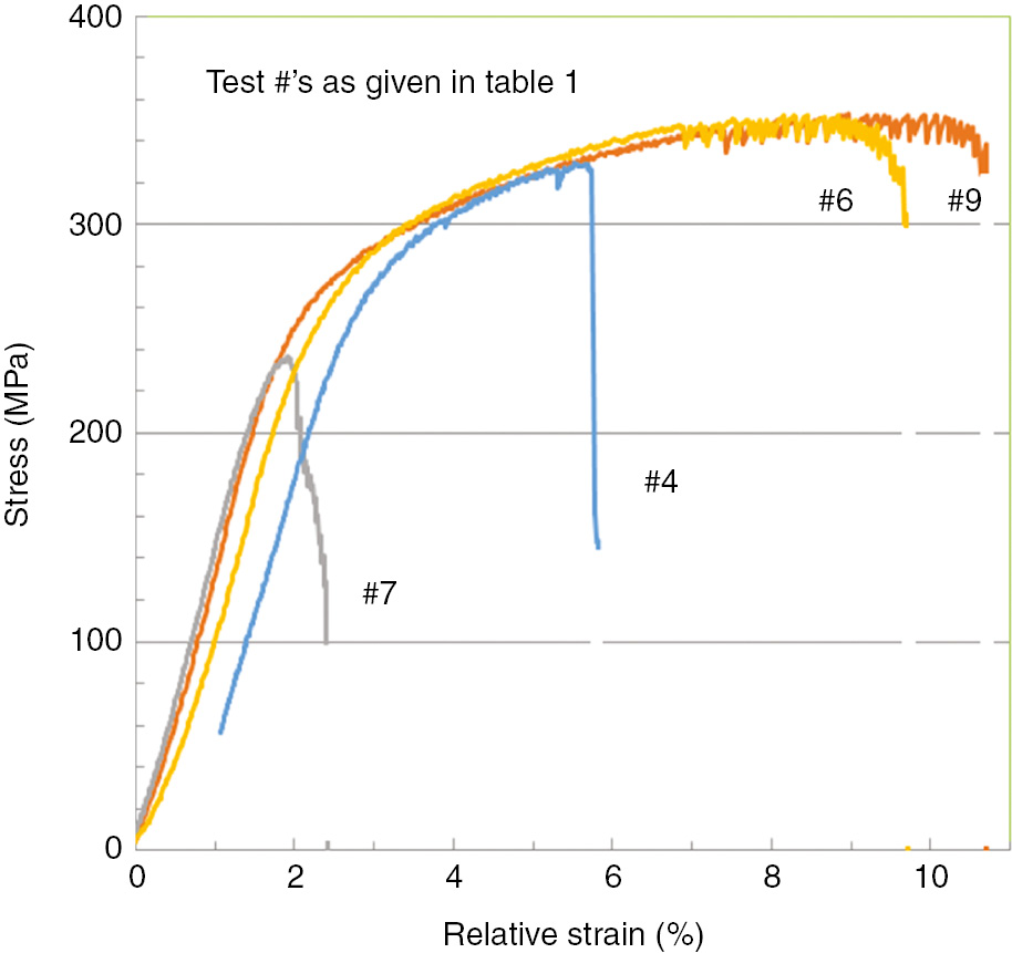
Representative engineering stress versus relative plastic strain curves for as-received and sensitized AA5083-H131 after pre-exposure to 0.6 m NaCl and then strained in either humid air (50% RH) or dry air at a nominal strain rate of 10−5/s.
SSRT data for AA5083-H131 subjected to SSRT at a nominal strain rate of 10−5/s in either humid air (50% RH) or dry air.
| Test # | Sensitization at 80°C | Exposure in 0.6 m NaCl (h) | UTS (MPa) | YS (MPa) | IGC depth (μm) | Type 1 EIC |
SSRT conditions | |
|---|---|---|---|---|---|---|---|---|
| KISCC (MNm-3/2) | Depth (μm) | |||||||
| 4 | None | 375 | 329 | 257 | 65–90 | 3.8 | 500 | Humid air |
| 6 | None | 375 | 353 | 255 | 60 | – | – | Dry air |
| 7 | 250 | 250 | 273 | 237 | 110 | 4.2 | 890 | Humid air |
| 9 | 250 | 250 | 354 | 245 | 110 | – | – | Dry air |
The relative extension data from the SSRT tests conducted in dry air (tests #6 and #9) were shifted in the analysis so that the load-extension (time) curves during the later stages of elastic behavior overlap with equivalent test conducted in humid air (tests #4 and #7) (Figure 2).
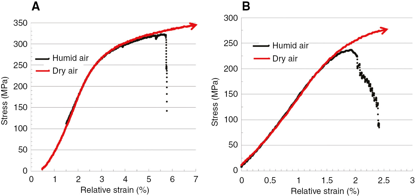
Comparison of the stress levels achieved in humid (50% RH) and dry air as function of the imposed extension during slow strain testing after pre-exposure to 0.6 m NaCl. (A) As-received AA5083-H131 +375 h in 0.6 m NaCl and (B) AA5083-H131 sensitized for 250 h at 80°C+250 h in 0.6 m NaCl.
Stress level differentials as a function of the extension imposed for SSRT conducted in humid and dry air are calculated and based on an assumption these stress differentials are directly relatable to losses of load-bearing area (see Equation 1); they are used in the estimation of the implied area of EIC generated as a function of the % relative strain. Estimated areas of EIC generated during the SSRT of AA5083-H131 in humid air (50% RH) are presented in Figure 3 as a function of time following the imposed stress during straining exceeding around 200 MPa.
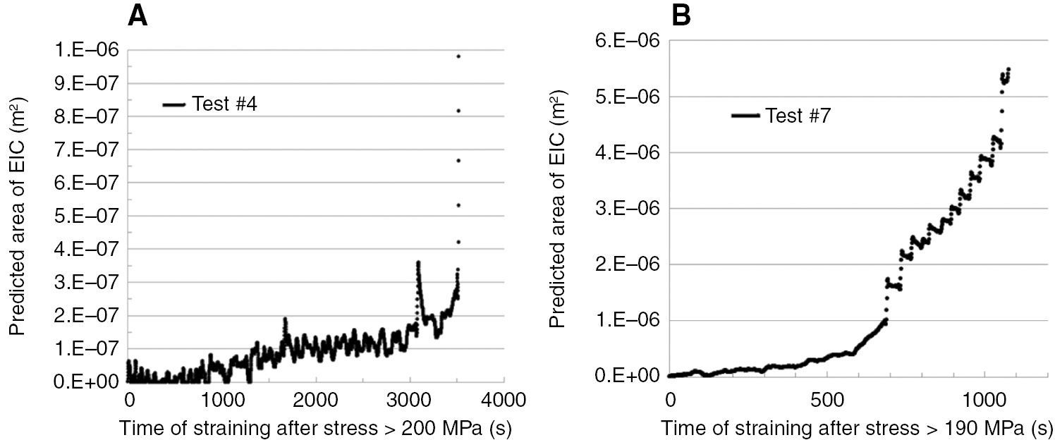
Estimated areas of EIC as a function of time during the SSRT of as-received (test #4) and sensitized (test #7) AA5083-H131 strained in humid air after pre-exposure to 0.6 m NaCl.
Maximum EIC crack depths as a function of the cracked area can be estimated for various crack shapes, such as elliptical, chord or an external peripheral ring. Crack depths are estimated assuming one main crack initiates from the external surface of the specimen with the results shown in Figure 4, where a “half-penny” aspect ratio is assumed for an elliptical crack, as often is observed during the early stages of EIC (Holroyd & Hardie, 1982; Burnett et al., 2017).
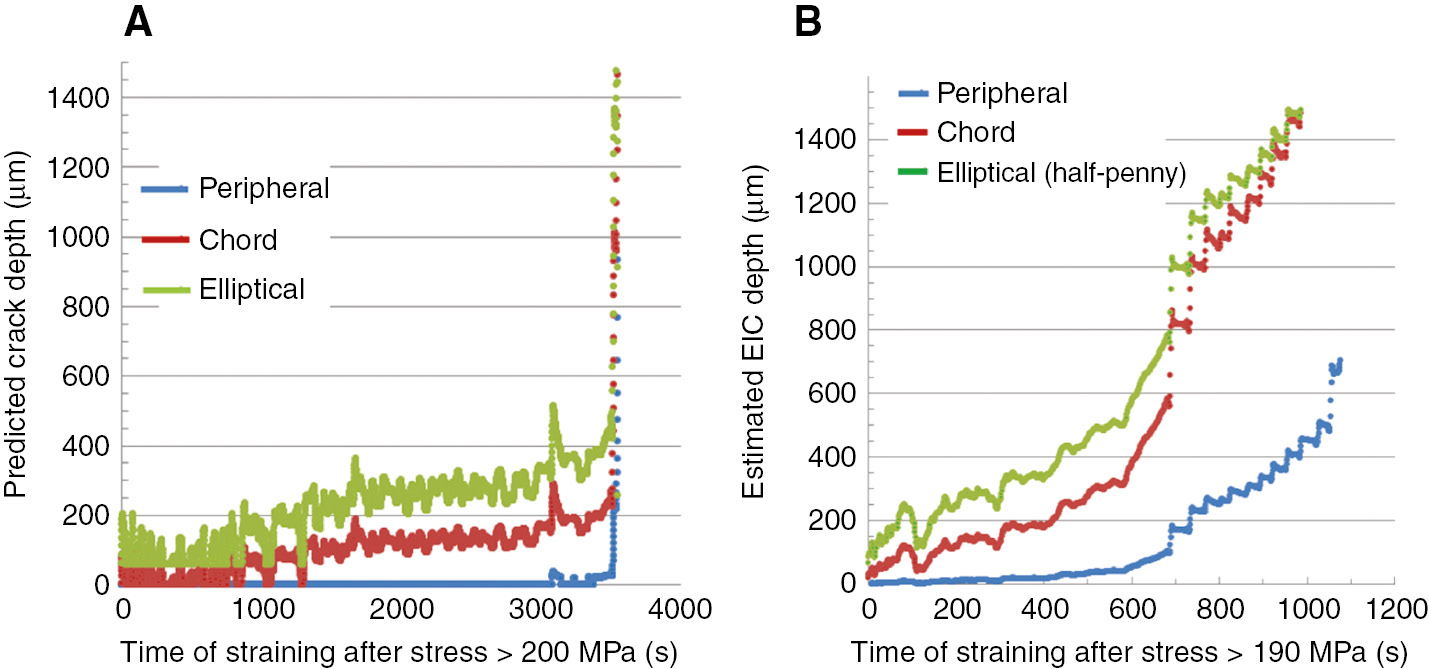
Estimated EIC depths for different crack geometries developed during the SSRT of as-received and sensitized AA5083-H131 pre-exposed to 0.6 m NaCl and strained in humid air at a nominal strain rate of 10−5/s. (A) As-received +375 h pre-exposure to 0.6 m NaCl and (B) sensitized for 250 h at 80°C+250 h in 0.6 m NaCl.
Having obtained the implied crack depths as a function of time for various crack shapes, we can now calculate the associated crack growth rates as a function of time (Figure 5). Then, using knowledge of the load applied during the SSRT as a function of time and assuming a crack profile, we can calculate the local stress intensity factor, K, as a function of time, using published relationships for stressed round bars (Stark & Ibrahim, 1986, 1987; Carpinteri, 1992; Shih & Chen, 2002) (Figure 6).
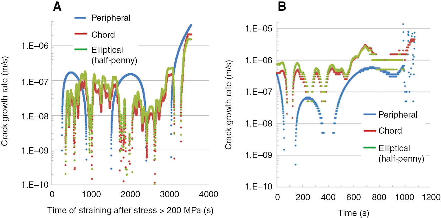
Predicted EIC growth rates for different crack geometries during the SSRT of as-received and sensitized AA5083-H131 pre-exposed to 0.6 m NaCl and strained in humid air at a nominal strain rate of 10−5/s. (A) As-received +375 h pre-exposure to 0.6 m NaCl and (B) sensitized for 250 h at 80°C +250 h in 0.6 m NaCl.
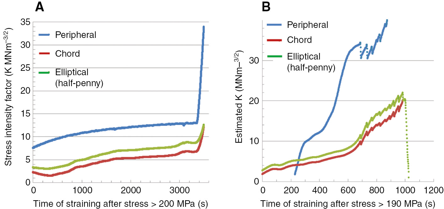
Predicted stress intensity factors for different crack geometries associated with EIC during the SSRT of as-received and sensitized AA5083-H131 pre-exposed to 0.6 m NaCl and strained in humid air at a nominal strain rate of 10−5/s. (A) As-received +375 h pre-exposure to 0.6 m NaCl and (B) sensitized for 250 h at 80°C +250 h in 0.6 m NaCl.
CV-K curves (Figure 7) are obtained using data provided in Figures 5 and 6.
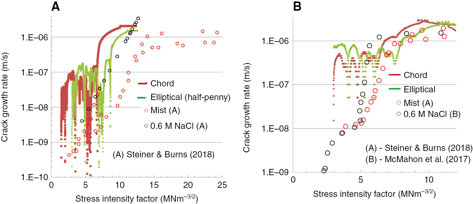
Predicted CV-K behavior (assuming different geometries) promoted during the SSRT of as-received and sensitized AA5083-H131 pre-exposed to 0.6 M NaCl and strained in humid air at a nominal strain rate of 10−5/s. (A) As-received +375 h pre-exposure to 0.6 m NaCl and (B) sensitized for 250 h at 80°C +250 h in 0.6 m NaCl. CV-K curves from literature (A,B) provided for comparison.
4 Discussion
Subjecting AA5083-H131 tensile specimens to pre-exposure in 0.6 m NaCl ahead of SSRT led to simultaneous hydrogen pre-charging and localized IGC providing local stress raisers, arguably transforming the originally smooth tensile specimens into pseudo pre-cracked test specimens but with little associated plasticity. This enables EIC initiation in humid air at considerably higher nominal strain rates than those required without pre-exposure (Holroyd et al., 2017a),b).
The agreement between maximum predicted EIC depths, obtained from analysis of load-extension data obtained during SSRT (Figure 8), and those observed on the fracture surfaces of failed SSRT tensile samples (Figure 9), for both the as-received and sensitized AA5083-H131, is remarkable, particularly considering our assumption to attribute load-bearing area losses during SSRT to a single region of EIC, when its evident multiple EIC cracks have initiated during SSRT and several typically contribute to SSRT failures (Figure 9).
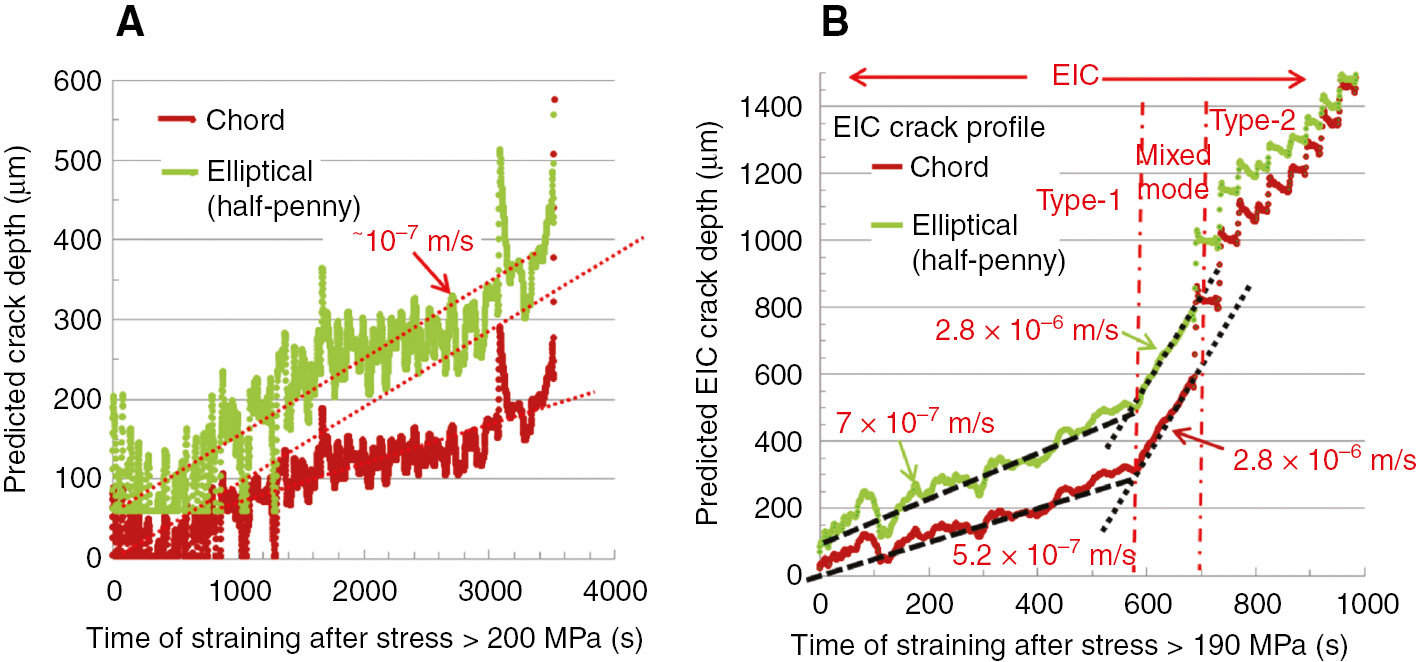
Predicted EIC depths for different geometries in AA5083 using load-extension data obtained during the SSRT of as-received and sensitized AA5083-H131 pre-exposed to 0.6 m NaCl and strained in humid air at a nominal strain rate of 10−5/s. (A) As-received +375 h pre-exposure to 0.6 m NaCl and (B) sensitized for 250 h at 80°C +250 h in 0.6 m NaCl.
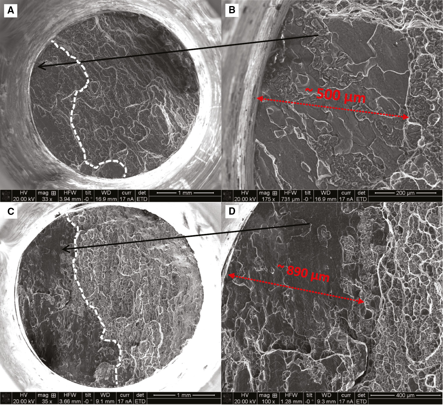
Scanning electron microscopy images of fracture surfaces of SSRT samples strained to failure in humid air (50% RH) at a nominal strain rate of 10−5/s. (A) AA5083-H131 as-received +375 h in 0.6 m NaCl (test #4), (C) AA5083-H131 +250 h at 80°C +375 h in 0.6 m NaCl (test #7); (B) and (D) are higher magnifications of (A) and (C), respectively.
Predicted EIC growth rates for the sensitized AA5083-H131 display a sudden increase when EIC depths exceed ~580 μm (Figure 8B), whereas no such increase was obvious for the as-received material (Figure 8A). It is interesting to note in harmony with these predictions, fracture mode evaluation during SSRT indicates the sensitized material underwent an EIC mode transition, from solely type 1 EIC to a mixed mode involving type 1 and type 2 EIC (Holroyd et al., 2017a),b), when EIC depths exceeded ~580 μm (Figure 9B), whereas limited type 2 EIC was detected in as-received material.
A more detailed comparison of the predicted and experimentally observed EIC behavior promoted during our SSRT of AA5083-H131 in humid air after pre-exposure to 0.6 m NaCl is provided in Table 2, from which it is apparent the predicted EIC depths are slightly lower than those observed experimentally. This difference we attribute to multiple EIC crack initiation and crack coalescence during SSRT, the results of which are apparent in the fracture surfaces shown in Figure 9.
Comparison of predicted and experimentally observed EIC characteristics promoted during the SSRT of as-received and sensitized AA5083-H131 in humid air (50% RH) after pre-exposure to 0.6 m NaCl.
| Observed (Holroyd et al., 2017a) |
Predictions using SSRT data |
||
|---|---|---|---|
| Type 1 EIC | Type 1 EIC | Type 2 EIC | |
| As-received | |||
| Depth (μm) | 500 | 400 | 400–500 |
| CV (m/s) | – | ~10−7 | >10−7 |
| K (MN−3/2) | 3.8–11.3 | >3–9 | >9 |
| Sensitized | |||
| Depth (μm) | 890 | 580 580–700a |
700–>1500 |
| CV (m/s) | – | ~7.10−7 ~2.8.10-6a |
Numerous sudden jumps (Av. CV) ~2.8.10−6 |
| K (MN−3/2) | 4.2–12.4 | 3–8 8–11a |
>11.0 |
-
aMixed mode type 1 and type 2 EIC.
Despite these differences, our initial findings indicate the accelerated test method presented here should be capable of quickly providing an indication of an aluminum alloy EIC threshold stress intensity factor, KIEIC, and its potential EIC susceptibility as a function of alloy sensitization/temper.
Perhaps the most significant evidence for our assertion that the CV-K characteristics for AA5083-H131 may be acquired in this way is provided by the following:
A recent three-dimensional (3D) tomography time-lapse study on the SSRT of pre-exposed sensitized AA5083-H131 material used here (Gudla et al., 2019), which confirms type 1 EIC initiation is typically associated with IGC stress raisers and occurs when stress levels exceed ~200 MPa with initial EIC growth predominantly evolving as a half-penny-shaped elliptical cracked region; and
Reasonable agreement exists between the predicted CV-K behavior and that reported for AA5083-H131 in similar tempers obtained using state-of-the-art fracture mechanics-based testing equipment (Steiner & Burns, 2018) (Figure 7).
5 Conclusions
An accelerated test method which can provide crack growth rate (CV) as a function of the applied stress-intensity factor (K) (i.e. the CV-K behavior) of EIC using SSRT is presented for as-received and sensitized AA5083-H131.
Predicted CV-K behavior closely resembles published experimental data obtained using sophisticated fracture mechanics-based test methods.
The new approach employs a pre-exposure treatment ahead of straining to pre-charge tensile test specimens with hydrogen, while simultaneously introducing local IGC sites to act as local stress raisers with limited associated local plasticity (i.e. “chemical” pre-cracking) during SSRT.
Estimation of EIC areas promoted during SSRT as a function of time is calculated, assuming stress reductions between SSRT in humid and dry air after given plastic extension reflect a loss of load-bearing area, which is directly attributable to an area of EIC.
3D time-lapse tomography studies of AA5083-H131 with identical sensitization, pre-exposure and SSRT conditions confirms the assumptions made on EIC initiation conditions and EIC growth for stress intensity factors up to around 15 MNm−3/2 (~50% KIC).
Acknowledgements
This work was carried out with the support of the Diamond Light Source, instrument I13 (proposal MT18165-1). Funding for B.P. and J.J.L. was provided by ONR-N00014-17-1-2573 and ONR-N00014-18-1-2608 along with the Arthur P Armington Professorship (J.J.L.) at Case Western Reserve University.
References
ASTM Standard E 1681-95. Standard test method for determining a threshold stress intensity factor for environmentally assisted cracking of metallic materials under constant load. In: ASTM Standard E 1681. Philadelphia: ASTM International, 1995.Search in Google Scholar
Burnett TL, Holroyd NJH, Lewandowski JJ, Ogurreck M, Rau C, Kelley R, Pickering EJ, Daly M, Sherry AH, Pawar S, Slater TJA, Withers PJ. Degradation of metallic materials studied by correlative tomography. In: 38th Riso International Symposium on Materials Science, IOP Conf. Series: Materials Science and Engineering, 219, 012001, 2017.10.1088/1757-899X/219/1/012001Search in Google Scholar
Carpinteri A. Elliptical-arc surface cracks in round bars. Fatigue Fract Mater 1992; 15: 1141–1153.10.1111/j.1460-2695.1992.tb00039.xSearch in Google Scholar
Domack MS. Evaluation of K1SCC and da/dt measurements for aluminum alloys using precracked specimens. In: Lisagor WB, Crooker TW, Leis BN, editors. Environmentally assisted cracking: science and engineering. Philadelphia, PA: ASTM STP 1049, 1990: 391–409.10.1520/STP24077SSearch in Google Scholar
Dietzel W. Characterization of susceptibility of metallic materials to environmentally assisted cracking. In: GKSS-Forschungszentrum GmbH, Geesthacht Report GKSS 99/E/24, 1999.Search in Google Scholar
Dietzel W. Standardization of rising load/rising displacement testing. In: Kane RD, editor. Environmentally assisted cracking: predictive methods for risk assessment and evaluation of materials, equipment and structures. West Conshohocken, PA: ASTM STP 1049, 2000: 317–326.10.1520/STP10227SSearch in Google Scholar
Dietzel W, Mueller-Roos J. Methods for investigating and testing – experience with rising load/rising displacement stress corrosion cracking testing. Mater Sci 2001; 37: 264–271.10.1023/A:1013214910345Search in Google Scholar
Gudla VC, Garner A, Palmer BC, Storm M, Lewandowski JJ, Withers PJ, Holroyd NJH, Burnett TL. Initiation and short crack growth behaviour of environmentally assisted cracks in AA5083-H131 investigated correlatively across time and length scales. Corr Rev 2019. https://doi.org/10.1515/corrrev-2019-0044.10.1515/corrrev-2019-0044Search in Google Scholar
Holroyd NJH, Hardie D. Effect of inherent defects on initiation of stress corrosion cracking in weldable Al-Zn-Mg alloys. Met Technol 1982; 9: 229–234.10.1179/030716982803285747Search in Google Scholar
Holroyd NJH, Scamans GM. Stress corrosion cracking of Al-Zn-Mg-Cu aluminum alloys in saline environments. Metall Mater Trans A 2013; 44A: 1230–1253.10.1007/s11661-012-1528-3Search in Google Scholar
Holroyd NJH, Burnett TL, Seifi M, Lewandowski JJ. Improved understanding of environment-induced cracking (EIC) of sensitized 5XXX series aluminum alloys. Mat Sci Eng A 2017a; 682: 613–621.10.1016/j.msea.2016.11.088Search in Google Scholar
Holroyd NJH, Burnett TL, Seifi M, Lewandowski JJ. Pre-exposure embrittlement of a commercial Al-Mg-Mn alloy. AA5083-H131. Corr Rev 2017b; 35: 275–290.10.1515/corrrev-2017-0037Search in Google Scholar
Hyatt MV. Use of precracked specimens in selecting heat treatments for stress corrosion resistance in high strength aluminum alloys. In: Boeing commercial airplane document DC-224467. Seattle, OR, 1969a.Search in Google Scholar
Hyatt MV. Effects of specimen geometry and grain structure on SCC behavior of aluminum alloys. In: Boeing commercial airplane document D6-24470. Seattle, OR, 1969b.Search in Google Scholar
Hyatt MV. Use of precracked specimens in stress corrosion cracking testing of high strength aluminium alloys. Corrosion 1970; 26: 487–503.10.5006/0010-9312-26.11.487Search in Google Scholar
ISO 7539-6. ISO Standard on corrosion of metals and alloys – stress corrosion testing; part 6: pre-cracked specimens. Geneva, Switzerland: International Organization for Standardization, 1998.Search in Google Scholar
Kaufman JG, Coursen JW, Sprowls DO. An automated method for evaluating resistance to stress corrosion cracking with ring-loaded precracked specimens. In: Craig HL, editor. Stress corrosion – new approaches. Philadelphia: ASTM STP 610, 1976: 94–107.10.1520/STP28673SSearch in Google Scholar
McEvily AJ, Clark JP, Bond AP. Effect of Thermo-Mechanical Processings on the Fatigue and Stress Corrosion of an Al-Zn-Mg Alloy. Trans Metal Society (AIME) 1967; 60: 661–667.Search in Google Scholar
McMahon ME, Steiner PJ, Lass AB, Burns TJ. The effect of temper and composition on stress corrosion of Al-Mg alloys. Corrosion 2017; 73: 347–361.10.5006/2317Search in Google Scholar
McNaughtan D, Worsfold M, Robinson MJ. Corrosion product force measurements in the study of exfoliation and stress corrosion cracking in high strength aluminium alloys. Corros Sci 2003; 45: 2377–2389.10.1016/S0010-938X(03)00050-7Search in Google Scholar
Mulherin JH. Influence of environment on crack propagation characteristics of high-strength aluminum alloys. In: Stress corrosion testing. Philadelphia: ASTM STP 425, 1967: 66–81.10.1520/STP46453SSearch in Google Scholar
Seifi M, Holroyd NJH, Lewandowski JJ. Deformation rate and sensitization effects on environmentally assisted cracking of Al-Mg naval alloys. Corrosion 2016; 72: 264–283.10.5006/1949Search in Google Scholar
Schra L, Faber J. Influence of environments on constant displacement stress corrosion crack growth in high strength aluminium alloys. In: National Aerospace Laboratory, Holland, 1981: Report NLR-TR 81138U.Search in Google Scholar
Shih YS, Chen JJ. The stress intensity factor study on an elliptical cracked shaft. Nucl Eng Design 2002; 214: 137–145.10.1016/S0029-5493(02)00022-5Search in Google Scholar
Speidel MO. Stress corrosion of aluminum alloys. Metall Trans A 1975; 6A: 631–651.10.1007/BF02672284Search in Google Scholar
Speidel MO, Hyatt MV. Stress corrosion of high-strength aluminum alloys. In: Advanced corrosion science technology, vol. 2. New York: Plenum Press, 1972: 115–335.10.1007/978-1-4615-8255-7_3Search in Google Scholar
Sprowls DO, Shumaker MO, Walsh JD, Coursen JW. In: Evaluation of stress corrosion cracking susceptibility using fracture mechanics techniques. George C Marshall Space Flight Center, Alabama, Final Report Contract NO. NAS-8021487, 1973: Part 1.Search in Google Scholar
Sprowls DO, Coursen JW, Walsh JD. Evaluating stress-corrosion crack-propagation in high-strength aluminum alloys with bolt loaded precracked double-cantilever-beam specimens. In: Craig HL, editor. Stress corrosion – new approaches. Philadelphia: ASTM STP 610, 1976: 143–156.10.1520/STP28676SSearch in Google Scholar
Sprowls DO, Bucci RJ, Ponchel BM, Brazil RL, Bretz PE. In: A study of environmental characterization of conventional and advanced aluminum alloys for selection and design – phase ii – the breaking load method. NASA Langley Research Center, Hampton, VA, NASA Contract NASI-116424 Report No. 172397, 1984.Search in Google Scholar
Stark HL, Ibrahim RN. Estimating fracture toughness from small specimens. Eng Fract Mech 1986; 25: 395–401.10.1016/0013-7944(86)90253-5Search in Google Scholar
Stark H, Ibrahim RN. Validity requirements for fracture toughness measurements obtained from small circumferentially notched cylindrical specimens. Eng Fract Mech 1987; 28: 455–460.10.1016/0013-7944(87)90190-1Search in Google Scholar
Steiner PJ, Burns TJ. Mechanistic studies of intergranular stress corrosion cracking in Al-Mg alloys under atmospheric conditions. Corrosion 2018: 1117–1131.10.5006/2853Search in Google Scholar
Willard HH, Smith GF. The preparation and properties of magnesium perchlorate and it use as a drying agent. J Am Chem Soc 1922; 44: 2255–2259.10.1021/ja01431a022Search in Google Scholar
©2020 N.J. Henry Holroyd et al., published by De Gruyter, Berlin/Boston
This work is licensed under the Creative Commons Attribution 4.0 International License.
Articles in the same Issue
- Frontmatter
- In this issue
- Editorial
- International Conference on Stress-Assisted Corrosion Damage V (Hernstein, Austria, July 15–20, 2018)
- General topics
- Building environmental history for Naval aircraft
- Discussion of some recent literature on hydrogen-embrittlement mechanisms: addressing common misunderstandings
- When do small fatigue cracks propagate and when are they arrested?
- Computational modeling of pitting corrosion
- Hydrogen-assisted cracking
- Hydrogen effects on mechanical performance of nodular cast iron
- Ductile-brittle transition temperature shift controlled by grain boundary decohesion and thermally activated energy in Ni-Cr steels
- Hydrogen diffusion in low alloy steels under cyclic loading
- Aluminum alloys
- Initiation and short crack growth behaviour of environmentally induced cracks in AA5083 H131 investigated across time and length scales
- Residual stress affecting environmental damage in 7075-T651 alloy
- Estimation of environment-induced crack growth rate as a function of stress intensity factors generated during slow strain rate testing of aluminum alloys
- Applied topics
- Corrosion modified fatigue analysis for next-generation damage-tolerant management
- Effect of confined electrolyte volumes on galvanic corrosion kinetics in statically loaded materials
- Quasi-static crack propagation in Ti-6Al-4V in inert and aggressive media