
Experimental investigations of a novel pressure microfoam preparation device for dust removal
-
Yonghe Li
 ,
Lina Tuo
,
Lina Tuo

Abstract
Compared with large size foam, pressure microfoam has the characteristics of a good pipeline transportation stability, good jet orientation, strong impact force, and strong ability to capture fine dust, which is more suitable for dust removal. The traditional foam preparation device has the disadvantages of high-pressure loss, poor foaming effect, and foam uniformity. To overcome the above shortcomings, the annular air supply vertical foam preparation device was proposed in the article. The foaming cylinder of the device adopts a vertical design to avoid the influence of uneven distribution of foam caused by gravity; the spiral nozzle is used to evenly spray the foaming liquid on the foaming mesh to increase the contact area between foam and airflow. The stainless steel wire mesh and cotton wire mesh are adopted to improve the reliability and durability of concave foaming mesh. The performance of the new device was obtained by the self-built experimental system. Finally, the field test shows that the conditions of the heading face could fully meet the requirements of the device for pressure water and compressed air, and the produced pressure microfoam can effectively control dust.
1 Introduction
The water-based two-phase foam has the characteristics of large dust receiving area, good adsorption dust performance, and strong ability to wet dust. By accumulating at the dust source, foam can suppress dust diffusion and significantly improve dust control effect [1,2]. The existing foam dust removal technology has been developed from the traditional full-section coverage to the directional cover dust source. That is, foam is transported to the nozzle through the pipe and sprayed directionally to the dust source within a certain distance from the dust source [3,4,5,6,7]. Compared with large size foam, pressure microfoam has the characteristics of a good pipeline transportation stability, good jet orientation, strong impact force, and strong ability to capture fine dust, which is more suitable for dust removal [8,9,10,11]. A typical mesh foam preparation device is shown in Figure 1. Foaming liquid is evenly sprayed on the foaming mesh through the nozzle. Then the airflow produced by the fan to the mesh can continue to produce foam in large quantities. The foam produced by the device is directly transported to the dust source, which cannot meet the demand of dust removal [12,13,14]. In the early 1980s, the former US Bureau of Mines first developed a compressed-air foam preparation device [15,16,17,18,19,20]. Through the turbulence component, foaming fluid and airflow create turbulent vortices, which increase the chance of mixing, collision, and extrusion of air and liquid, thus producing pressure microfoam. The device has been applied in crusher, transfer point, and roadheader. The turbulence components mainly consist of metal wire, small ball, and baffle, which have the disadvantages of high-pressure loss and poor foaming effect [21,22]. Due to the influence of gravity, the flow rate of foaming liquid in the upper and lower parts of the turbulence component is uneven, so the uniformity of the foam becomes worse. To overcome the above shortcomings, a new foam preparation device is proposed in the study.
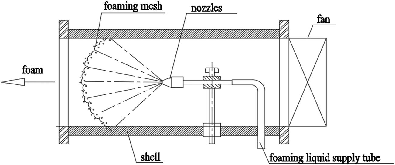
Typical mesh foam preparation device.
2 Structure and design principle of the novel foam preparation device
Figure 2 shows the designed annular air supply vertical foam preparation device, including foaming liquid inlet and compressed-air inlet, the foaming cylinder, the concave foaming mesh, the foam outlet, the foaming liquid spiral nozzle, and annular air supply chamber. The structure of the spiral nozzle is a ring cavity and a spiral. The foaming liquid disperses into small droplets after being contacted and impacted with the gradually smaller spiral surface. The divergence angle of the nozzle is 90°–120°, which can form a uniformly atomization area. The number of concave foaming mesh ranges from four to ten. The annular air supply chamber is separated by the outer wall of the foaming cylinder and the outer wall of the cylinder, and communicates with the air inlet. Two small air inlets are symmetrically opened on the small cylinder to ensure that the air enters the foaming chamber evenly.
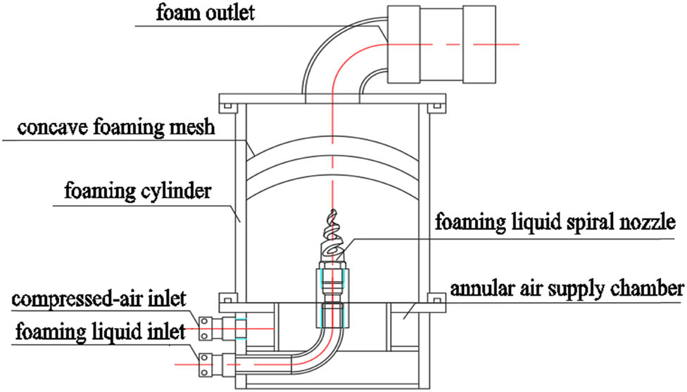
Structure of annular air supply vertical foam preparation device.
When the device is working, the foaming liquid is sprayed evenly to the foaming mesh through the spiral nozzle, forming a liquid film on the mesh surface. At the same time, the compressed air enters the foaming cylinder from the two small air inlets. The foam solution film on the foaming mesh produces foam continuously and uniformly under the action of the compressed air. Driven by the upstream pressure, the foam is transported to the downstream spraying device through the foam transportation pipeline at a high outlet pressure and, finally, pressure microfoam is produced with high foaming ratio and a long spraying distance.
The foaming cylinder of the device adopts a vertical design to avoid the influence of uneven distribution of foam caused by gravity; the spiral nozzle is used to evenly spray the foaming liquid on the foaming mesh to increase the contact area between foam and airflow. The stainless steel wire mesh can maintain the stability of the mesh hole for a long time, and the cotton mesh can retain an adhesive foam.
3 Experimental test system of foam preparation device
3.1 Foam preparation device
To obtain the working parameters of the foam preparation device, we designed the related experimental system to test the foaming capacity, which included the effects of the foaming liquid flow rate, the airflow rate, the foaming agent adding ratio, and the outlet pressure on foam amount and the expansion ratio.
Figure 3 shows the experimental system to test the device’s performance constructed by the author. The 3WH95-10/10 variable frequency piston pump (water volume 0–10 m3/h, pressure 0–10 MPa) is used to provide the foaming liquid. By adjusting the frequency converter, the foaming liquid can be transferred to the foam generator quantificationally. The compressed air is provided by BLT-75A air compressor (airflow is 0–600 m3/h, pressure 0–0.8 MPa).
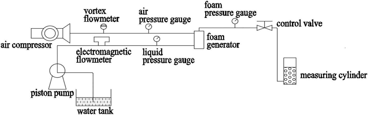
Experimental system of foam preparation device.
In the experiment, an electromagnetic flowmeter and vortex flowmeter were used to measure the flow rate of the foaming liquid and compressed air. Three pressure gauges were used to measure the outlet pressure of air pressure, water pressure, and foam pressure. The foam outlet is connected to the self-designed measuring cylinder to measure foam volume, and the foaming time is recorded using mechanical stopwatch to calculate the foam flow rate.
3.2 Selection of foaming liquid
The foaming liquid used in this study is a mixture system of anionic surfactant fatty alcohol polyoxyethylene ether sodium sulfate (AES) and nonionic surfactant fatty alcohol polyoxyethylene ether glucose (AEG), in which the ratio of AES and AEG is 1:1. The reasons for choosing this combination are as follows. Anionic surfactants are electronegative in water, and most coal dust surfaces are electronegative as well. The electrical repulsion between the two will hinder the close adsorption of anionic surfactants on coal dust surfaces. Nonionic surfactants are not affected by this electrical repulsion and can adsorb more closely on the surface of coal dust, so nonionic surfactants have a stronger ability to wet coal dust. However, compared with anionic surfactants, nonionic surfactants have a weak water-locking ability, resulting in a poor foam stability. Through some previous experiments, we know that foaming and wettability are best when the ratio of the two is 1:1.
4 Discussion on the results of device’s performance
4.1 Effect of foaming liquid flow rate on foaming performance
It can be seen from Figure 4 that when the foaming liquid flow rate remains unchanged, with the increase of the airflow rate, the foam amount tends to increase linearly and then tends to be stable. When the foaming liquid flow rate is 1, 1.2, 1.4, 1.6, 1.8, and 2.0 m3/h, the corresponding maximum foam amount is 25.6, 28.2, 33.8, 38.5, 40.9, and 44.1 m3/h, the expansion ratio also shows similar changes.
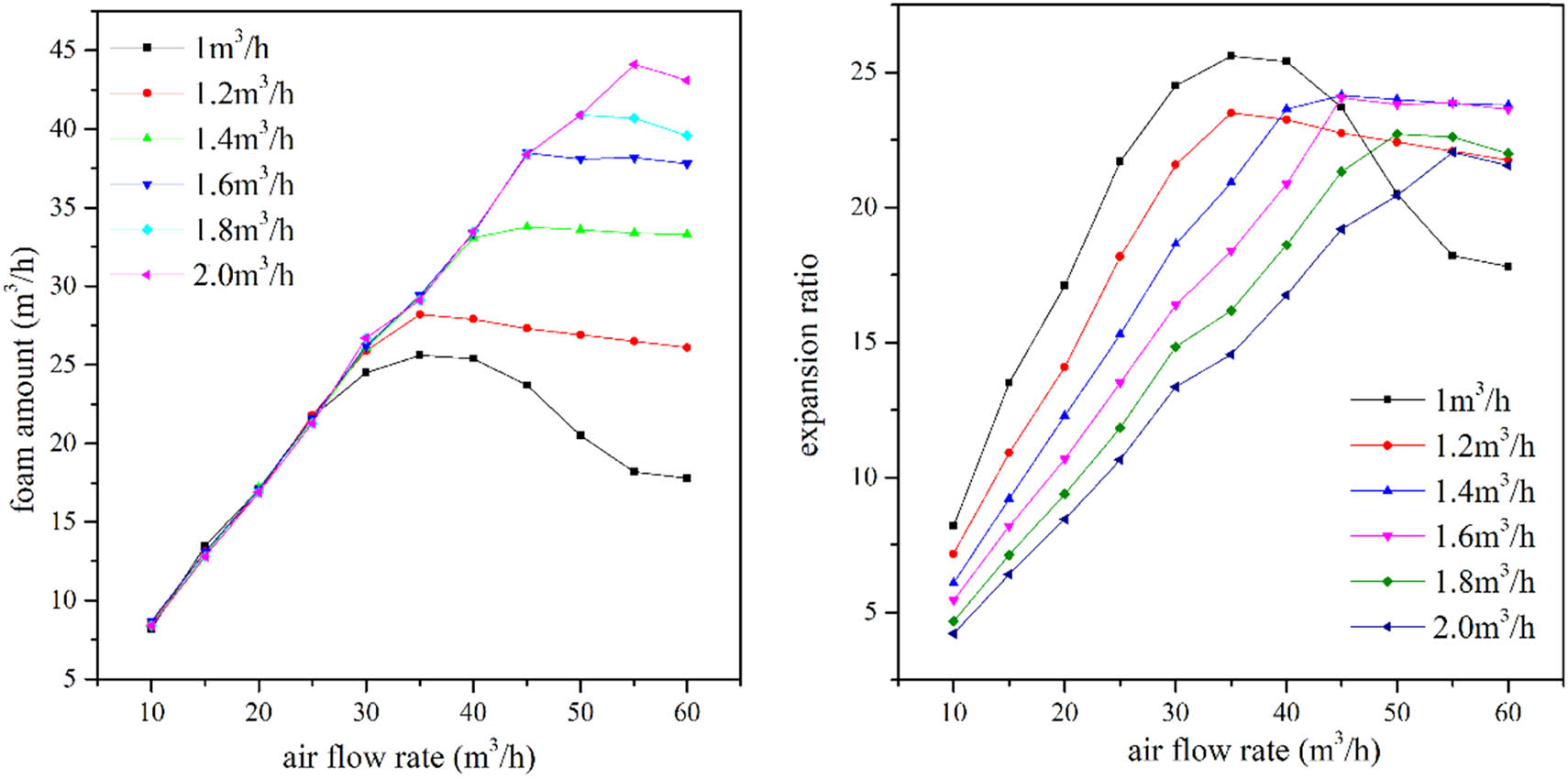
Diagram of the influence of airflow on foam volume and expansion ratio.
The reason is as follows. When the airflow rate is small, the gas is sufficiently in contact with the foaming liquid, the gas flow rate is not enough to make the solution fully foamed, and the liquid film of the foam is thick. At this point, the gas flow rate determines the foam amount. Therefore, the foam amount increases with the increase of airflow rate. When the airflow rate increases to a certain value, the gas content of the foam reaches a critical value, and the foam amount reaches a maximum value. At this time, the ratio of the airflow rate and the foaming liquid flow rate is optimal, and the expansion ratio is the highest. As the airflow rate continues to increase, the foaming liquid is not enough to wrap all the gas, the stability of the foam becomes worse and bursts seriously, the size distribution is uneven, and foam amount significantly decreases. It can also be seen from Figure 4 that at the same airflow rate, with the increase of foaming liquid flow rate, the foam amount gradually increases, but the expansion ratio gradually decreases. This is because the larger the flow rate of foaming liquid, the more chances it has to form foam. It is still possible to produce foam with the outside air after foam is sprayed. However, the foam amount is mainly determined by the airflow rate. Under the same airflow rate, the smaller the foaming liquid flow rate, the more chance it has to produce foam with the compressed air, and the greater the expansion ratio.
Figure 5 shows that as the airflow rate increases, the air–foam ratio remains unchanged first and then gradually increases. As the foaming liquid flow rate increases, the airflow rate at the inflection point also gradually increases. The airflow rate at the inflection point is substantially the same with the airflow rate corresponding to the maximum foam amount at the liquid flow rate. This is because the air is basically used for foaming until the maximum amount of foam is reached. Therefore, the air–foam ratio is kept stable, and the air–foam ratio of different foaming liquid flow rate has little difference. When the maximum foam amount is reached, excessive air cannot be used for foaming, resulting in a rising air–foam ratio, as shown by the curve.
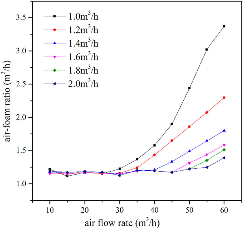
The relationship between airflow rate and air–foam ratio.
4.2 Effect of foaming liquid flow rate on foaming performance
As shown in Figure 6, the trend of foam amount varies with the liquid flow rate can be divided into three parts, depending on the airflow rate. When the airflow rate is ≤30 m3/h, the foam amount remains basically unchanged with the increase of the liquid flow rate. This is because the gas flow rate at this time cannot reach the minimum gas flow rate amount required for the liquid flow rate of 1 m3/h; therefore, the gas flow rate determines the foam amount. When the gas flow rate is fixed, the foam amount is basically kept constant. When gas flow rate is >30 m3/h and ≤50 m3/h, the foam amount increases first with the increase of the liquid flow rate and remains basically stable afterward. This is because the gas flow rate at this time has exceeded the optimal value required for the liquid flow rate of 1 m3/h. As the liquid flow rate increases, more foam will be produced. When the liquid flow rate increases until the airflow rate is its optimal value, the foam amount is basically stable. When the gas flow rate is ≥50 m3/h, the gas amount has exceeded the optimal gas flow rate of 2 m3/h. At this time, the foaming liquid flow rate determines the foam amount, and the foam amount gradually increases as the foaming liquid flow rate increases. The variation exhibited by the expansion ratio can be explained by the above theory.
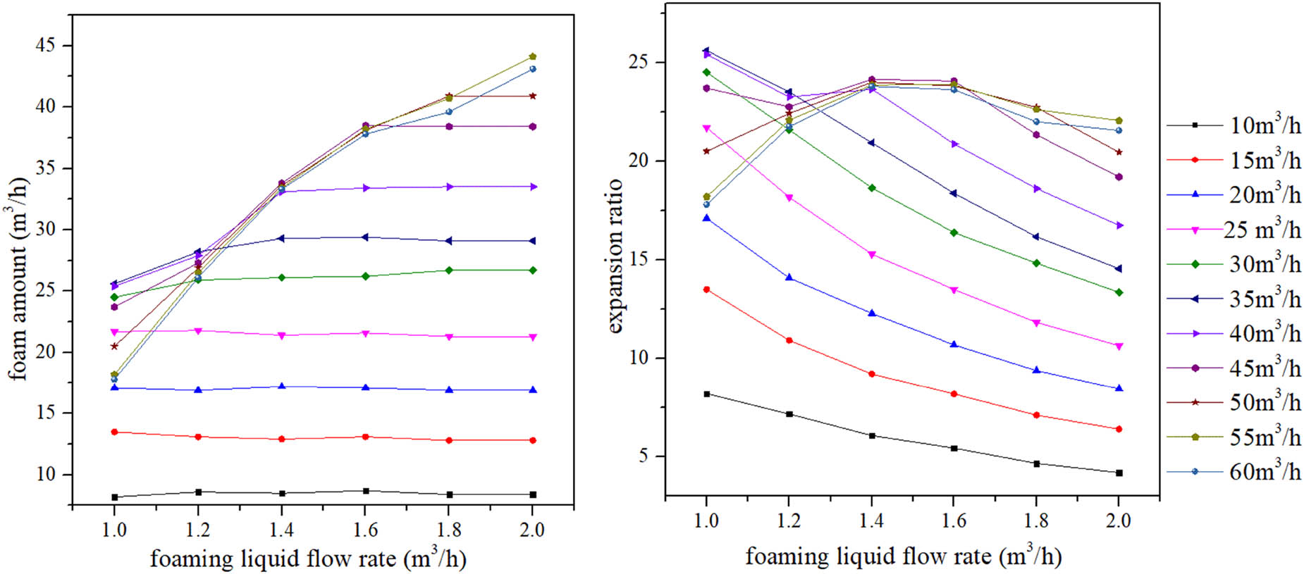
Relationship between the foam amount and expansion ratio of liquid flow rate.
4.3 Effect of foaming agent addition ratio on foam amount and expansion ratio
As shown in Figure 7, when the foam generator is in the optimal liquid and airflow rate, increasing the foaming agent addition ratio from 0.1% of the foaming liquid, we can find that the foam amount will increase first, then remain unchanged, and the optimal addition ratio is 0.4%. The reason is as follows. Surfactants can form foam because of the adsorption of molecules on the surface of the liquid film. When the number of surfactant molecules increases, the amount of adsorption on the liquid surface also increases, and the ability to form bubbles is enhanced. When the adsorption is saturated, the surfactant will no longer accumulate on the surface of the liquid film. At this time, the foaming ability is maximized. After the surfactant saturates the surface of the liquid, the molecules will form micelles in the solution. In the process of foam formation, the presence of micelles leads to the thickening of foam liquid film, and some foaming agents in the liquid film are not involved in the formation of foam. As a result, the carrying rate of foam increases, leading to the decrease of foaming efficiency.
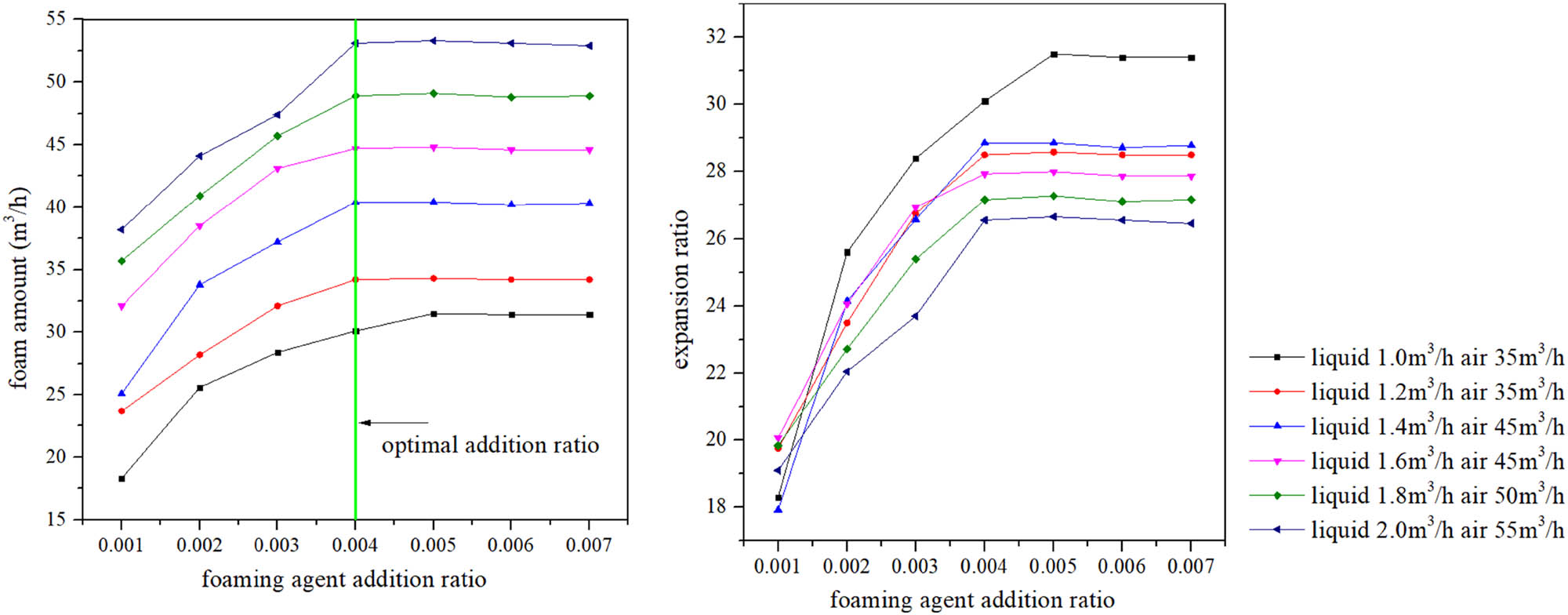
Relationship between foam amount and expansion ratio of different foaming agent addition ratio.
4.4 Effect of outlet pressure on air pressure and foam amount
Figure 8 shows that the air pressure increases linearly with the increase of outlet pressure. Therefore, the outlet pressure is mainly determined by the air pressure. The outlet pressure of the device can be increased effectively by increasing the air pressure. When the outlet pressure is below the critical value, the fluctuation of the pressure does not substantially affect the foam amount. When the critical value is exceeded, the increase of the pressure will cause severe foam breakage, and the foam amount drops linearly. The critical outlet pressure varies with the liquid and airflow rate. The larger the liquid and airflow rate, the greater the critical pressure. To ensure that there is sufficient foam amount for dust reduction, the outlet pressure must be below the critical outlet pressure during operation.
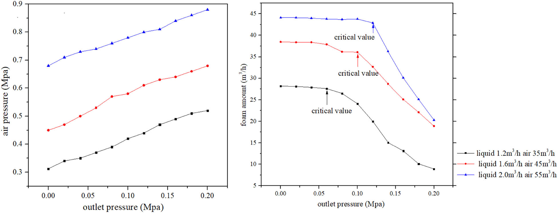
Relationship between air pressure and foam amount of outlet pressure.
5 Field test
As shown in Figure 9, a water mist-foam integrated preparation system was made by combining the new foam preparation device and water mist device. The water mist part of the system has been introduced in the related articles, this study focuses on the effect of foam dust removal.
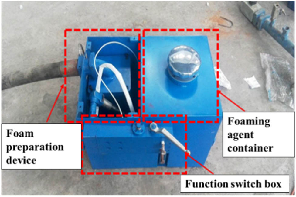
Water mist-foam integrated preparation system.
A roadway in Guizhou province was selected as the test site for foam dust removal. the foam preparation device is fixed on the body of the roadheader, and the downhole compressed air and pressure water are, respectively, connected to the device. The produced foam is distributed to the nozzle on the cutting arm of the roadheader through the distributor. The nozzle is mounted on a movable flexible support. After installation, adjust the air supply and water flow of the foam system to achieve the optimal value.
In this study, the dust removal effect of the foam technology was evaluated based on the safety industry standard AQ 1020-2006 “Technical specifications for integrated control of dust in underground coal mines.” During the tunneling of the roadheader, two dust measuring points were arranged at the driver’s position and the roadheader’s return wind side, which is 5 m away from the driver and 1.5 m away from the floor. Figure 10 shows the location of the dust measuring points.
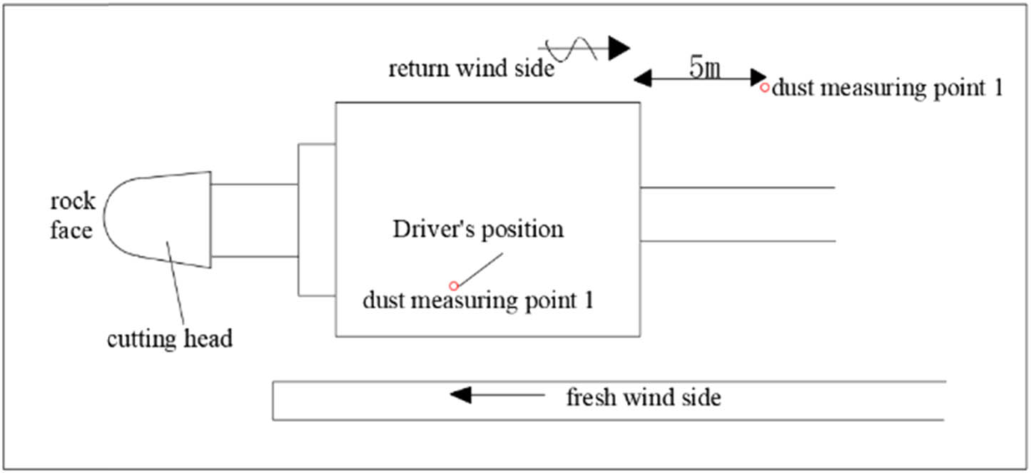
Location of dust point in fully mechanized mining face.
According to the test, as shown in Tables 1 and 2, the dust removal efficiencies of total dust and respirable dust at the driver’s side is 94 and 93%, respectively, and 92 and 93%, respectively, at the return wind side. Through the use of foam technology, the site environment has been significantly improved.
Dust concentration at the driver’s position
| The driver’s position | Without measures | Foam | ||
|---|---|---|---|---|
| Total dust | Respirable dust | Total dust | Respirable dust | |
| Measured data (mg/m3) | 1010.3 | 247.8 | 59.9 | 17.6 |
| 1012.1 | 250.1 | 61.2 | 17.3 | |
| 1012.1 | 248.4 | 61.0 | 17.3 | |
| Average concentration (mg/m3) | 1011.5 | 248.8 | 60.7 | 17.4 |
Dust concentration at the return wind side position
| The return wind side position | Without measures | Foam | ||
|---|---|---|---|---|
| Total dust | Respirable dust | Total dust | Respirable dust | |
| Measured data (mg/m3) | 725.0 | 165.0 | 52.5 | 12.5 |
| 722.5 | 167.5 | 60.0 | 10.0 | |
| 720.0 | 165.0 | 52.5 | 12.5 | |
| Average concentration (mg/m3) | 722.5 | 165.8 | 55.0 | 11.7 |
6 Conclusion
(1) The annular air supply vertical foam preparation device, which can produce pressure microfoam was proposed. The new foaming device adopts vertical design to avoid uneven distribution of foam caused by gravity. The spiral nozzle is used to spray foaming liquid, and the annular air supply can ensure even airflow and increase the contact area between foaming liquid and airflow.
(2) The working parameters of the foam preparation device were obtained by self-built experimental system. With the increase of the airflow rate, the foam amount tends to increase linearly and then becomes stable when the foaming liquid flow rate remains unchanged. As the airflow rate increases, the air–foam ratio remains unchanged first and then gradually increases. The airflow rate at the inflection point is substantially the same with the airflow rate corresponding to the maximum foam amount at the liquid flow rate. When the foam generator is in the optimal liquid and airflow rate, the optimal addition ratio is 0.4%. The outlet pressure is mainly determined by the air pressure, and the fluctuation of outlet pressure does not substantially affect the foam amount when the outlet pressure is below the critical value.
(3) The foaming device was tested on the spot. The existing pressure water and compressed air in the mine were used to prepare microfoam, and the foam was sprayed into the dust producing area of the roadheader in a directional way through the nozzle arranged near the cutting head, so as to suppress the dust production. The dust removal rate of the technology is more than 90%, significantly improving the site environment.
Acknowledgments
This study has been funded by the National Natural Science Foundation of China (51904158), China Postdoctoral Science Foundation (2020M671469), the Introduction of Talent Research Start-up Fund of Nanjing Tech University and Jiangsu Graduate Scientific Research Innovation Program (SJCX21_0440).
-
Conflict of interest: Authors state no conflict of interest.
References
[1] Wang QG, Wang DM, Han FW, Yang F, Sheng YX. Study and application on foam-water mist integrated dust control technology in fully mechanized excavation face. Process Saf Environ Prot. 2020;133:41–50.10.1016/j.psep.2019.11.008Suche in Google Scholar
[2] Wang QG, Wang DM, Wang HT, Xu CH. Influence of alkyl polyglucoside and fatty alcohol ether sulfate on the foaming and wetting properties of sodium dodecyl benzene sulfonate for mine dust control. Powder Technol. 2019;345:91–8.10.1016/j.powtec.2018.12.084Suche in Google Scholar
[3] Ren WX. Study on the theory and technology of foam dust removal in underground coal mine. Xuzhou: China University of Mining and Technology Press; 2009. p. 15–35.Suche in Google Scholar
[4] Wang HT, Wang DM, Ren WX. Application of foam to suppress rock dust in a large cross-section rock roadway driven with roadheader. Adv Powder Technol. 2014;24:257–62.10.1016/j.apt.2012.06.012Suche in Google Scholar
[5] Price FH. Dust suppression (pneumoconiosis) experiments at a Kent Colliery. Colliery Guardian. 1946;172:517–21.Suche in Google Scholar
[6] Mullins CR. Dust suppression in Yorkshire-Foam boring and wet boring in stone drifts. Iron Coal Trades Rev. 1950;160:1221–5.Suche in Google Scholar
[7] Horner A. Prevention of dust deposits from B coming Airborne, and the suppression of dust at the source of dormation. Proceedings of Meeting of Experts on the Prevention and Suppression of Dust in Mining. vol. III, 1952. p. 190–4.Suche in Google Scholar
[8] Cole HW. Microfoam for the control of source and fugitive dust emissions. Specialty Conference on fugitive dust issues in the coal use cycle; 1983. p. 167–81.Suche in Google Scholar
[9] Cole HW, Klemmer CR. Dust suppression in coal mines. Pittsburgh: USBM & DeTer Co., Inc.; 1972. p. 60–80.Suche in Google Scholar
[10] Chen DS. The whole rock roadheader’s foam extinguishes dust. Coal Mine Mech Electr. 1986;12:7–8.Suche in Google Scholar
[11] Seibel RJ. Dust control at a transfer point using foam and water sprays. Pittsburgh: USBM; 1976. p. 1–16.Suche in Google Scholar
[12] Hiltz RH. Underground application of foam for suppression of respirable coal dust. Pittsburgh: USBM & Monsanto Research Corp; 1974.Suche in Google Scholar
[13] Page SJ, Volkwein JC. Foams for dust control. Eng Min J. 1986;10:50–4.Suche in Google Scholar
[14] Wang HT, Wang DM, Ren WX. Research status and development trend for foam dust control technique in underground coal mines. Metal Mine. 2009;39:131–4.Suche in Google Scholar
[15] Jiang ZA, Jin LZ, Jin RY. Discussion on the number of similarity criterion in foam dust removal. J Liaoning Technical Univ Eng. 1999;18:445–7.Suche in Google Scholar
[16] Jiang ZA, Li HY. Research and application of foam dust removal technology. Chin J Saf Sci. 1997;7:53–7.Suche in Google Scholar
[17] Wang DM, Ren WX, Wang BB. The invention relates to a foam dedusting system for underground coal mine. China; 2009, Patent no. 2008100235783.Suche in Google Scholar
[18] Fushun Coal Research Institute. High expansion Foam extinguishing its application coal mine. Beijing: Coal Industry Press; 1980. p. 10–5.Suche in Google Scholar
[19] Mukherjee SK, Singh MM. Spraying foam helps control longwall dust. Coal Age. 1984;89:54–6.Suche in Google Scholar
[20] Laurito AW, Singh MM. Evaluation of air sprays and unique foam application methods for longwall dust control. Pittsburgh: Engineers International, Inc.& U.S. Bureau of Mines; 1987.Suche in Google Scholar
[21] Parrett FW. Foam suppressants-an alternative for dust control. Ind Miner. 1986;220:52–3.Suche in Google Scholar
[22] Shen RC. Review on the structure design of foam generator. Pet Machinery. 1983;21:52–5.Suche in Google Scholar
© 2022 Yonghe Li et al., published by De Gruyter
This work is licensed under the Creative Commons Attribution 4.0 International License.
Artikel in diesem Heft
- Regular Articles
- Experimental investigations of a novel pressure microfoam preparation device for dust removal
- Influence of hydrothermal aging on the mechanical performance of foam core sandwich panels subjected to low-velocity impact
- Experimental study on surface wrapping strengthening of EPS particles and its concrete performance
- Modification of mechanical properties of Shanghai clayey soil with expanded polystyrene
- A new EPS beads strengthening technology and its influences on axial compressive properties of concrete
- A novel superabsorbent material based on soybean straw: Synthesis and characterization
- Use of line laser scanning thermography for the defect detection and evaluation of composite material
- Research on back analysis of meso-parameters of hydraulic cemented sand and gravel based on Box-Behnken design response surface
- Hot deformation behavior and microstructure of a 0.5 wt% graphene nanoplatelet reinforced aluminum composite
- Analysis of electromagnetic characteristics of the proposed composite four-rail electromagnetic launcher
- Preparation and characterization of a graphene hybridizing polyurethane damping composite
- Effects of layup parameters and interference value on the performance of CFRP–metal interference fit joints
- Vibration and noise reduction of pipelines using shape memory alloy
- Finite element analysis of behavior and ultimate strength of composite column
- Dynamic response of functionally graded plate under harmonic load with variable gradient parameters
- Deformation behavior of rubber composite based on FEA and experimental verification
- Effects of Z-pin on moisture absorption property and damage mode under flexural load for carbon fiber composite
- Design and testing of a smart rubber stave for marine water-lubricated bearings
- Study of carbon nano-modifier of fly ash in cement concrete mixtures of civil engineering
- Analysis of multiple impact tests’ damage to three-dimensional four-directional braided composites
- Theoretical analysis of aluminum honeycomb sandwich panel supported by reinforced concrete wall under low-speed impact load
- Effects of local fiber discontinuity on the fatigue strength parameter at the fiber inclusion corner in fiber-reinforced composites
- Experimental investigation on compressive properties of three-dimensional five-directional braided composites in hygrothermal environment
- Failure process of steel–polypropylene hybrid fiber-reinforced concrete based on numerical simulations
- A simple method for measuring the monofilament diameter of continuous filament yarn with high bending stiffness via synthetic laser imaging
- Span length effect on flexural properties of composite laminate reinforced with a plain weave carbon fiber fabric in a polymer matrix
- Mechanical properties improving and microstructure characterization of inorganic artificial stone binder
- Effect of thermal treatment process on the structure of C/SiO2 composite aerogels
- Mechanical and corrosion resistance analysis of laser cladding layer
- Wear and corrosion mechanisms of Ni–WC coatings modified with different Y2O3 by laser cladding on AISI 4145H steel
- Damage and failure analysis of composite stiffened panels under low-velocity impact and compression after impact with damp-heat aging
- In-situ CT characterization of 2D woven SiCf/SiC composite loading under compression
- Effect of the manufacturing process on the equivalency qualification of glass fiber reinforced polymer
- Study of concrete properties based on crushed stone sand mixture and fiber of fly ash of thermal power plants
- Establishment of wear mechanism distribution diagram of ZTAp-reinforced iron matrix composites
- Calculation method of elastic modulus for carbon fiber-reinforced plastics considering inhomogeneous interphase
- An experimental study on the failure and enhancement mechanism of bolt-strengthening GFRP T-joint subjected to tensile loading
- The viability of cell that encapsulated in calcium alginate hydrogel beads
- Discussion of ceramic bar reinforced TWIP steel composite structure
- A theoretical framework underlying an accelerated testing method and its application to composites under constant strain rates and fatigue loading
- Theoretical analysis of interfacial design and thermal conductivity in graphite flakes/Al composites with various interfacial coatings
- Multiscale heat conduction and fractal oxidation behaviors of needle-punched carbon/carbon composites
- Numerical simulation of composite grid sandwich structure under low-velocity impact
- Wear properties of Al/TiO2 composites fabricated via combined compo-casting and APB process
- Review Articles
- Application of melanin as biological functional material in composite film field
- Review on research progress of cemented sand and gravel dam
- Communication
- Fabrications and microstructure analysis of cobalt-based coatings by an easy-coating and sintering process
- Letter to the Editor
- Investigation on mechanical and conductive behaviors of nano-graphite-based concrete