Design and static testing of wing structure of a composite four-seater electric aircraft
-
Kang Yang
 ,
Yi-lin Guo
,
Yi-lin Guo

Abstract
Because of its light weight, high strength, designable, composite materials are more and more widely used in the field of aerospace, especially in the field of general aviation. In this paper, the structural design and analysis of the composite wing (include wing beam, rib, skin, leading edge and trailing edge) of a four-seater electric aircraft were carried out. The finite element numerical analysis model of the composite wing was established, and the deformation and strain distribution of the composite wing under the limited load required by airworthiness regulations were calculated. Finally, the static test of the whole composite wing was carried out to verify the accuracy of the finite element results. The finite element analysis and testing results showed that the structural design of the composite wing of the electric aircraft meets the structural strength requirements specified in the airworthiness standard (part 23 of China civil aviation regulations: air-worthiness requirements for normal, practical, special effects and commuting aircraft: CCAR 23-R3)
1 Introduction
In recent years, Europe and other developed countries are calling for improving the environmental protection performance of aircraft and building green aviation. Many institutions are working to alleviate the impact of aviation on the environment. The emergence of new energy electric aircraft provides a bright technical way for the thorough greening of aviation [1, 2, 3, 4, 5, 6, 7, 8]. In addition, because of the more and more extensive application of composite materials in the field of aviation [1, 2, 3, 4, 5, 6, 7, 8], the design and manufacture of light-weight and high-strength composite structures has become one of the challenges faced by the development of electric aircraft [1]. Yang K et al. [12] conducted finite element analysis and static testing on composite wing of a two-seater electric aircraft. The stress distribution at the reference point and the wing tip deformation obtained from the testing and analysis results were in good agreement. At the same time, it was verified that the composite wing structure meets the requirements for aircraft structure strength in ASTM F2245-11 [13]. Du Chunzhi et al. [14] designed the composite structure of the wing of a low-speed aircraft in the way of layering and geometric modeling, and analyzed the strength and stiffness of the wing in different layering by ANSYS finite element software. The results showed that the composite wing had lighter weight, higher strength and greater stiffness than the traditional wing under the same working condition. Wang Tong and Wu Zhen [15] based on the wing model of aircraft which named x, established the wing model of half composite, all composite and all metal with the method of equal rigidity design, and carried out the finite element analysis under the same aerodynamic shape and load with ABAQUS software. The analysis results showed that the weight of half composite wing was about 35% less than that of all metal wing, and the weight of all composite wing was nearly 50% less than that of all metal wing. Smith, H. W. [16] studied the structural design, the static testing equipment and the testing method of hydrogen fuel light UAV. The test results were in good agreement with the previous analysis results. In order to meet the requirements of long-life, Zhang W et al. [17] carried out lightweight design for the structure of small ultra light solar UAV according to the mechanical characteristics of the structure, and the rationality of the structure was verified by the finite element analysis and static testing method. Finally, the finite element modal analysis was carried out, and then the finite element analysis results were modified according to the modal testing results. The agreement obtained was very good between the experimental results and the theoretical predictions. Simsiriwong j [18] has studied the static and vibration characteristics of the wing and fuselage structure of a full-size carbon fiber composite of the ultra light UAV, and designed a hydraulic system and a tail fixing device, obtained the static response, natural frequency, damping coefficient and vibration mode of the two structures under the simulated load. In the above research and other available literature, there were no research about the composite wing structure design and analysis of a four-seat electric aircraft.
In this paper, the structural design method of the composite wing of a four-seater electric aircraft was studied. Then, the structural model of the wing was numerically simulated by the finite element analysis software. Finally, the static testing and analysis results of the full-size composite wing were compared to verify whether the wing structure meets the CCAR 23-R3 [19] airworthiness clause, which showed the rationality of the wing structure design, and provided a certain reference for relevant researchers to carry out the structural design of the same level of aircraft.
2 Structural design of the composite wing
2.1 The structure and connection of wing
The overall dimensions and structural of the aircraft and wing were shown in Figure 1 and Figure 2. The span was 13500mm (the flap span was 3650mm, the aileron span was 2000mm), the maximum take-off weight was 1200Kg, and the maximum overload was +3.8g/−1.52g. The wing consisted of main wing, flap and aileron. The main wing was single beam structure, and the wing beam was I-beam structure of cross section, which was located at the maximum thickness of the wing (about 30% chord length).
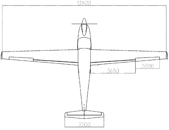
Outline dimension diagram of aircraft (/mm)
Mechanical property of materials
| mechanical properties | W-3021FF | SW110c-100a | UIN 23100 | H604PSC |
|---|---|---|---|---|
| E11/GPa | 59.0 | 26.8 | 136.0 | 0.0012 |
| E22/GPa | 59.0 | 26.8 | 0.037 | – |
| G12/GPa | 9.5 | 7.3 | 0.037 | – |
| V12 | 0.062 | 0.126 | 0.33 | 0.32 |
The wing and fuselage were connected by pins, which were fixed by four rib pins to transfer the wing shear and torque to the fuselage. The left and right wing beams were connected by two wing beam butt pins to realize the moment self-balance of the wing, as shown in Figure 3.
2.2 The materials and ply design of the wing
The wing was made of carbon fiber/glass fiber composite (manufacturer was Weihai Guang-wei composite material Co., Ltd.) and foam sandwich structure, materials and brand name: 3K carbon cloth (W-3021FF), carbon fiber unidirectional prepreg (UIN 23100), glass fiber cloth (SW110c-100a) and foam (H60 4 PSC). The mechanical properties of each material were shown in Table 1. The main parts of the wing (include skin, root rib, flange strip of wing beam, web, front/rear edge of wing) used hand lay-up method and were laid shown in Table 2.
Layout of wing main structure
| the main parts | quantity | orientation* |
|---|---|---|
| skin | 14 | s45/[t0]3/p/t0/s0 |
| front edge | 4 | [t0]2 |
| rear edge | 8 | t0/[t45]2/t0 |
| root rib | 28 | [t0/t45]2/[t0]10/[t0/t45]2 |
| flange strip | 40 | [u45]/[u(−45)]/[u0]29/[u(−45)]/[u45] |
| web | 44 | [t0]8/[p4]2/[t0]20/[t45]13/p |
Note: 45 indicated that the woven fabric was in ±45°orientation. 0 indicated the 0°/90°orientation of the woven fabric. s indicated the glass fiber cloth. t indicated 3K carbon cloth. u represents carbon fiber unidirectional prepreg. P represent foam.
3 Finite element analysis and wing static testing
3.1 Finite element analysis model
In the finite element analysis, HyperMesh software was used for mesh generation, boundary condition setting, other pre-processing and post-processing. Nx.nastran software was used for calculation. The finite element model used the triangle/quadrilateral shell, and the connection of the pin used the MPCs (a contact algorithm for shell) to associate the two components. The boundary constraint points were the root rib pin and the wing beam butt pin. The numbers of element were 86360 and the numbers of node were 192664, and the finite element model shown in Figure 7.
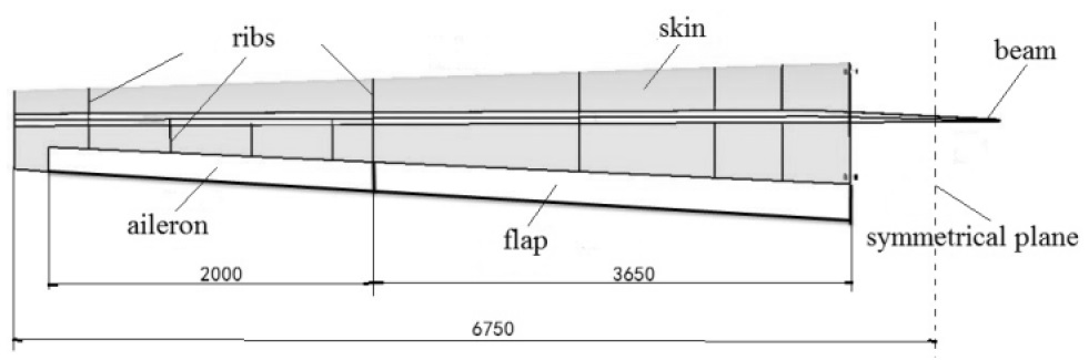
The wing structure (/mm)

Schematic diagram of wing-fuselage connection
3.2 Static testing of the wing
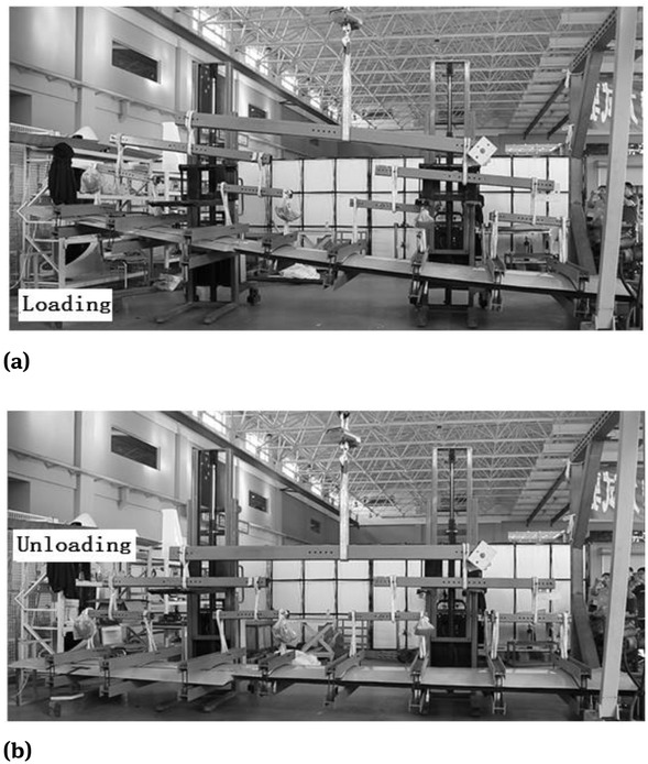
The static test of the wing was carried out by the combination of the clamp pallet and the lever system. The levers were divided into three levels. The restraint points of the test piece were the root rib pins and the wing beam butt pins, as shown in Figure 4(a). The loading equipment was electric portal jib crane, and tension was monitored by tension meter, as shown in Figure 4(b).

The loading system of wing
The wing was divided into 8 regions from the wing root to the wing tip, and the boundary of each region was between the two adjacent pallets. According to the principle of equivalent shear force and bending moment, all aerodynamic forces and inertia forces in this area were combined. Similarly, the location of each loading point in chord direction was determined according to the principle of equivalent shear force and bending moment.
According to the requirements of relevant provisions of CCAR 23-R3: for normal, practical and commuter aircrafts, symmetrical wing load test under the case A (in the flight envelope of the aircraft, the limited maneuvering load point of the aircraft) was required. In Table 3 and Figure 5, the location and load of the clamp pallets were shown. Due to the symmetrical loading of the left and right wings, so the left wing was selected for loading test, and loaded to the limit load which was 67% of the ultimate load.
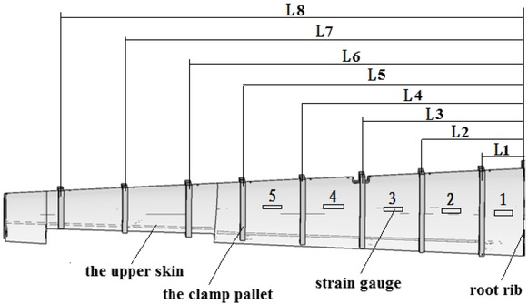
Position of strain gauge
Position and limit loads of wing clamp
| NO. | Distance from wing root/mm | The limit load/N |
|---|---|---|
| L1 | 501 | 2552 |
| L2 | 1215 | 1955.8 |
| L3 | 1925 | 2171 |
| L4 | 2635 | 1916.6 |
| L5 | 3349 | 1554 |
| L6 | 3993 | 1454 |
| L7 | 4753 | 1042.5 |
| L8 | 5513 | 1954 |
3.3 Testing project and equipments
Static testing measurement data included tip deformation and strain at reference point of the wing. The deformation of wing tip was recorded by placing a steel scale. For the strain measurement, pasted the strain gauge symmetrically on the upper/lower skin of the left wing at the middle between the clamp pallet, and between the clamp pallet and the root rib, along the direction of the main wing beam, as shown in Figure 5. Moreover, the strain collection system used Donghua-DH3820 high-speed strain gauge which made in China, the strain gauge model was BF350-5AA(11)N6-X and produced by CETCA. And all the above equipments were qualified after verification.
4 The static testing and finite element analysis results
After the testing was loaded to the limit load and kept for 30s shown in Figure 6. There were no abnormal sound and damage on the wing. At this time, the deformation of the wing tip was 772mm. And after unloading, the deformation of the wing tip was 16mm relative to the initial state. The preliminary analysis was caused by the assembly clearance of each component. The deformation was small and the wing does not have plastic deformation. Therefore, the strength of the wing structure met the requirements of CCAR 23-R3 airworthiness clause (clause 23.305 stipulates that the structure must be able to bear the limited load without harmful permanent deformation and under any load until the limited load, the deformation will not affect the safe operation).
The result of static testing
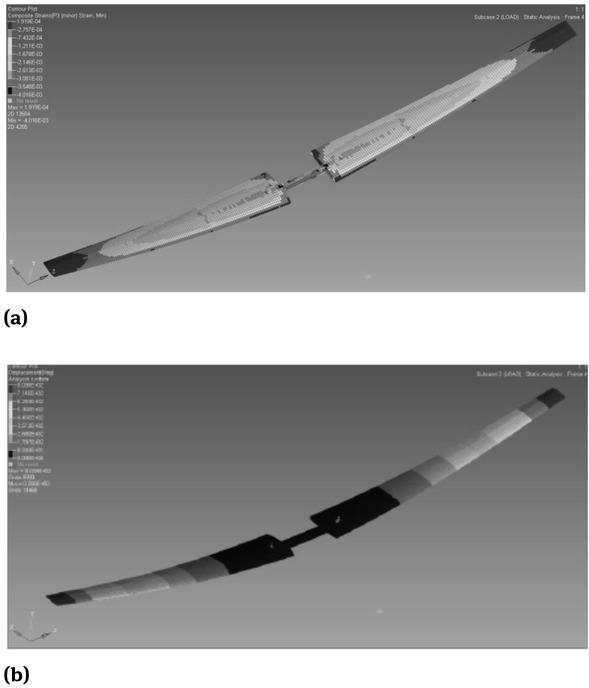
The result of finite element (FE) analysis, (a) is the strain distribution nephogram, (b) is the deformation distribution nephogram
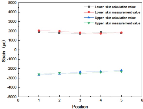
The result of strain measurement and FE analysis
For the strain measurement results, the maximum value of the upper wing skin was −2586με, and the lower wing skin was 2047με. According to the testing results and the finite element analysis results shown in Figures from 6 to 8, the maximum deformation calculation value of wing tip was 803mm, the maximum calculation value of upper wing skin strain was −2730με, and the maximum calculation value of lower wing skin was 1919με. The difference between the finite element analysis and the testing value was small. The wing tip deformation was shown in Table 4, so the strain measurement value and the wing tip deformation testing result were in good agreement with the corresponding finite element analysis calculation value. Therefore, the results of finite element analysis were accurate and reliable.
The deformation of measurement and FE analysis to the left wing tip
| Results | The deformation of wing tip /mm |
|---|---|
| measurement | 772 |
| FE analysis | 803 |
| relative error | 4.0% |
5 Conclusion
In this paper, the finite element method was used to analyze whether the structural design of the composite wing of a four-seater electric aircraft can meet the strength requirements of airworthiness regulations under limit load. The results were verified by full-scale wing static testing and the conclusions were as follows:
The force transfer route between wing and fuselage met the requirements of the aircraft structural strength.
Under the limit load, the wing structure had no plastic deformation and damage, and the structural strength met the requirements of CCAR 23-R3 air-worthiness regulations for normal, practical, special and commuter aircraft.
The results of the finite element analysis were in good agreement with the experimental results, which proved the applicability of the finite element analysis results.
The connection design of wing and fuselage had certain reference significance for relevant structural designers.
References
[1] HUANG Jun, YANG Fengtian. Development and challenges of electric aircraft with new energies. Acta Aeronautica et Astronautica Sinica. 2015; 37(1):57-68.Suche in Google Scholar
[2] LIN Z M. Making aviation green. Advance in Manufacturing. 2013; 1:42-49.10.1007/s40436-013-0008-3Suche in Google Scholar
[3] HYDER A K. A century of aerospace electrical power technology. Journal of propulsion and power. 2003; 19(6):1155-1179.10.2514/2.6949Suche in Google Scholar
[4] STEINER H, VRATNY PC, GOLOGANC, et al. Optimum number of engines for transport aircraft employing electrically powered distributed propulsion. CEAS Aeronautical Journal. 2015; 5(2):157-170.10.1007/s13272-013-0096-6Suche in Google Scholar
[5] SALANM A, EUNUS Z I. Recent green aviation technologies an overview. Journal of Modern Science and Technology. 2013; 1(1):61-75.Suche in Google Scholar
[6] TOMAZIZ T, PLEVNIK V, VEBLE G, et al. Pipistrel Taurus G4: On creation and evolution of the winning aero-plane of NASA green flight challenge 2011.Journal of Mechanical Engineering. 2011; 57(12):869-878.10.5545/sv-jme.2011.212Suche in Google Scholar
[7] BRUCE P G,FREUNBERGER S A,HARDWICK J J, et al. LiO2 and LIS batteries with high energy storage. Nature Materials. 2012; 11(1):19-29.10.1038/nmat3191Suche in Google Scholar PubMed
[8] SRILATHA A R. Design of a 4-seat general aviation electric aircraft. San Jose: San Jose State University; 2012.Suche in Google Scholar
[9] Tang Jianmao. Review of studies of carbon fiber resin matrix composites. SPACECRAFT ENVIRONMENT ENGINEERING. 2010; 27(3): 269-280.Suche in Google Scholar
[10] Zhang Xianhua, Gao Yanqiu, et al. Development and applications of carbon nanotubes and continuous carbon fiber reinforced composites. Aeronautical Manufacturing Technology. 2014; 459(15):71-73.Suche in Google Scholar
[11] BAO Jianwen, JIANG Shicai, ZHANG Daijun. Current status and trends of aeronautical resin matrix composites reinforced by carbon fiber. Science & Technology Review. 2018; 36(19): 52-63.Suche in Google Scholar
[12] Kang Yang, Liguo Zhang, Shude Ji, Yumei Yue, Wang Ji. Static testing and analysis of composite wing of a two-seater aircraft powered by Li-ion battery electric propulsion. Advanced Composites Letters. 2016; 25(6):127-131.10.1177/096369351602500601Suche in Google Scholar
[13] ASTM F2245-11, Standard Specification for Design and Performance of a Light Sport Airplane.Suche in Google Scholar
[14] DU Chunzhi, FU Boyu, QIU Zhihao. Design and finite element analysis of composite wing for a low speed aircraft. JOURNAL OF MACHINE DESIGN. 2019; 36(S2):55-58.Suche in Google Scholar
[15] Wang Tong, Wu Zhen. Finite element analysis for simulate composite wing of X model aircraft. Journal of Shenyang Aerospace University. 2011; 28(05):48-51.Suche in Google Scholar
[16] SMITH, Howard W. Static test of an ultralight airplane. Journal of Aircraft. 1988; 25(1):37-40.10.2514/6.1986-2600Suche in Google Scholar
[17] Zhang W, Yao L J, Tong X Y. Structural Design and Testing of Small Ultralight Solar-Powered Unmanned Aerial Vehicle. Advanced Materials Research. 2011; 317-319:227-230.10.4028/www.scientific.net/AMR.317-319.227Suche in Google Scholar
[18] Simsiriwong J. Structural testing of an ultralight UAV composite wing and fuselage. Dissertations & Theses Grad-works; 2009.Suche in Google Scholar
[19] CAAC. Part 23 of China civil aviation regulations: airworthiness requirements for normal, practical, special effects and commuting aircraft: CCAR 23-R3. Beijing: CAAC.Suche in Google Scholar
© 2020 K. Yang et al., published by De Gruyter
This work is licensed under the Creative Commons Attribution 4.0 International License.
Artikel in diesem Heft
- Regular Articles
- Microstructure and compressive behavior of lamellar Al2O3p/Al composite prepared by freeze-drying and mechanical-pressure infiltration method
- Al3Ti/ADC12 Composite Synthesized by Ultrasonic Chemistry in Situ Reaction
- Microstructure and photocatalytic performance of micro arc oxidation coatings after heat treatment
- The effect of carbon nanotubes on the mechanical and damping properties of macro-defect-free cements
- Toughening Mechanism of the Bone — Enlightenment from the Microstructure of Goat Tibia
- Characterization of PVC/MWCNTs Nanocomposite: Solvent Blend
- Study on Macroscopic and Mesoscopic Mechanical Behavior of CSG based on Inversion of Mesoscopic Material Parameters
- Bearing properties and influence laws of concrete-filled steel tubular arches for underground mining roadway support
- Comparing Test Methods for the Intra-ply Shear Properties of Uncured Prepreg Tapes
- Investigation of Microstructural, Mechanical and Corrosion Properties of AA7010-TiB2 in-situ Metal Matrix Composite
- A Comparative Study of Structural Changes in Conventional and Unconventional Machining and Mechanical Properties Evaluation of Polypropylene Based Self Reinforced Composites
- Research on Influence mechanism of composite interlaminar shear strength under normal stress
- Mechanical properties of geopolymer foam at high temperature
- Synthesis and mechanical properties of nano-Sb2O3/BPS-PP composites
- Multiscale acoustic emission of C/SiC mini-composites and damage identification using pattern recognition
- Modifying mechanical properties of Shanghai clayey soil with construction waste and pulverized lime
- Relationship between Al2O3 Content and Wear Behavior of Al+2% Graphite Matrix Composites
- Static mechanical properties and mechanism of C200 ultra-high performance concrete (UHPC) containing coarse aggregates
- A Parametric Study on the Elliptical hole Effects of Laminate Composite Plates under Thermal Buckling Load
- Morphology and crystallization kinetics of Rubber-modified Nylon 6 Prepared by Anionic In-situ Polymerization
- Effects of Elliptical Hole on the Correlation of Natural Frequency with Buckling Load of Basalt Laminates Composite Plates
- Effect of interphase parameters on elastic modulus prediction for cellulose nanocrystal fiber reinforced polymer composite
- Mixed Matrix Membranes prepared from polysulfone and Linde Type A zeolite
- Fabrication and low-velocity impact response of pyramidal lattice stitched foam sandwich composites
- Design and static testing of wing structure of a composite four-seater electric aircraft
- CSG Elastic Modulus Model Prediction Considering Meso-components and its Effect
- Optimization of spinning parameters of 20/316L bimetal composite tube based on orthogonal test
- Chloride-induced corrosion behavior of reinforced cement mortar with MWCNTs
- Statistical Law and Predictive Analysis of Compressive Strength of Cemented Sand and Gravel
- Young’s modulus and Poisson’s ratio of the deformable cement adhesives
- Reverse localization on composite laminates using attenuated strain wave
- Impact of reinforcement on shrinkage in the concrete floors of a residential building
- Novel multi-zone self-heated composites tool for out-of-autoclave aerospace components manufacturing
- Effect of notch on static and fatigue properties of T800 fabric reinforced composites
- Electrochemical Discharge Grinding of Metal Matrix Composites Using Shaped Abrasive Tools Formed by Sintered Bronze/diamond
- Fabrication and performance of PNN-PZT piezoelectric ceramics obtained by low-temperature sintering
- The extension of thixotropy of cement paste under vibration: a shear-vibration equivalent theory
- Conventional and unconventional materials used in the production of brake pads – review
- Inverse Analysis of Concrete Meso-constitutive Model Parameters Considering Aggregate Size Effect
- Finite element model of laminate construction element with multi-phase microstructure
- Effect of Cooling Rate and Austenite Deformation on Hardness and Microstructure of 960MPa High Strength Steel
- Study on microcrystalline cellulose/chitosan blend foam gel material
- Investigating the influence of multi-walled carbon nanotubes on the mechanical and damping properties of ultra-high performance concrete
- Preparation and properties of metal textured polypropylene composites with low odor and low VOC
- Calculation Model for the Mixing Amount of Internal Curing Materials in High-strength Concrete based on Modified MULTIMOORA
- Electric degradation in PZT piezoelectric ceramics under a DC bias
- Cushioning energy absorption of regular polygonal paper corrugation tubes under axial drop impact
- Erratum
- Study on Macroscopic and Mesoscopic Mechanical Behavior of CSG based on Inversion of Mesoscopic Material Parameters
- Effect of interphase parameters on elastic modulus prediction for cellulose nanocrystal fiber reinforced polymer composite
- Statistical Law and Predictive Analysis of Compressive Strength of Cemented Sand and Gravel
- Retraction
- Assessment of nano-TiO2 and class F fly ash effects on flexural fracture and microstructure of binary blended concrete