Toughening Mechanism of the Bone — Enlightenment from the Microstructure of Goat Tibia
-
Xiaohan Wang
 ,
Dongxu Li
,
Dongxu Li

Abstract
With the continuous advancement of space exploration missions, the mechanical environment for planetary detectors is becoming increasingly severe. As a result, fatigue, fracture, large deformation and other forms of failures are more likely to occur at the load-bearing structures. As a critical part of the load-bearing structure of a goat, goat tibia has remarkable toughness because of its unique microstructures. In this investigation, firstly, the cortical bone of goat tibia was observed by SEM, and the characteristic microstructures in different regions were identified. Secondly, the cross section of cortical bone was loaded by long-term inplane stress, then the toughness of cortical bone in different regions are obtained and compared based on the orientation and distribution of cracks after the load. Thirdly, a simplified FEM model mimicking typical microstructure of the cortical bone is proposed using cohesive modeling, and then the toughening mechanism of the typical microstructure is validated with numerical simulation. Finally, the toughening mechanisms of cortical bone were discussed according to the SEM observation as well as the numerical simulation. This study of the toughening mechanism of cortical bone can be helpful for the biomimetic design of high-toughness structures.
1 Introduction
With the development of lunar exploration mission and Mars exploration project, detectors, such as lunar rover and Mars rover, must have novel load-bearing structures that can maintain excellent mechanical properties under complex mechanical environment. When structures subjected to a load for a long time, even if the load is far less than the rated load, tiny cracks may still occur and continue to grow [1]. These tiny cracks can lead to structure fatigue, and reduce the strength of the structures. In severe cases, they even cause damaging deformation failure or fracture failure of the structure. "Toughness" reflects the ability of the structure to resist the generation and propagation of tiny cracks [2]. Therefore, it is urgent to design and develop novel load-bearing structures with high toughness.
Bone is a composite composed mainly of protein and hydroxyapatite. As the main supporting and load-bearing structure in land-living animals, bone has excellent mechanical properties [3, 4]. Goat tibia is a good example, which is tough enough to ensure that the large-scale structural deformation, fatigue or fracture would not happen under everyday long-time running and frequently jumping of a healthy adult goat. The outstanding toughness of bone is closely related to its microstructure [5, 6].
There are two main types of bone: cortical bone and trabecular bone. The cortical bone forms a dense, hard outer shell that mostly contributes to bone strength and toughness [3]. Therefore, this investigation takes the cortical bone as a research object. The basic unit of cortical bone is a lamella of a few microns thick [7, 8]. By different arrangements, lamellae form into different microstructures in cortical bone, such as: osteon, layered lamellae and interstitial bone. Cortical bone can be divided into outer, middle and inner regions from outside to inside, featuring different microstructures.
In recent years, a large number of theoritical, numerical and experimental researches on cortical bone have been carried out. Jäger and Fratzl [9] proposed a staggered arrangement of platelets in a collagen matrix to form the mineralized collagen fibril, and employed a shear-lag model to assess the effective elastic modulus and strength of this geometric system. This staggered geometry became the basis for many analytical and computational models of bone that followed. Najafi, A. R. et al. [10] used the linear elastic failure theory to analyze the effects of osteon and cement lines on crack propagation under tension and compression loads, respectively.
Cohesive modelling is one of the most used numerical methods to handle fracture and toughness mechanics problems. Ural, A et al. [11, 12] established the cohesive finite element model of the middle region of cortical bone, and simulated the process of crack generation and propagation, and the toughening mechanisms of osteon and cement line were discussed especially. Siegmund et al. [13, 14] used a two-dimensional cohesive FEM model with a traction-separation law to study the role of interfaces and collagen cross-linking on the stiffness and strength of a mineralized collagen fibril. Luo et al. [15] also used a two-dimensional cohesive FEM model to investigate the effect of mineral–collagen interfacial behaviour on the micro damage progression in bone by considering three different types of interfaces. Abdelwahed et al. [16], developed a three-dimensional FEM model to study the relationship between the hierarchical structure and the properties of the mineralized collagen microfibrils and to investigate their equivalent nanomechanical properties.
The extended finite-element method (XFEM) has also been used to study the crack generation and propagation in cortical bone. Li, S et al. [17], with X-FEM method, simulate the process of crack propagation in the middle region, and analyzed the comprehensive effects of osteon and cement line in preventing the crack growth. Using XFEM, Budyn et al. [18, 19, 20] performed extensive studies on cortical bone and investigated the effects of different parameters on stress and strain distributions, failure, and fracture of bone. They modelled a multiple crack growth in human cortical bone under tension in order to create a constitutive law at the macroscopic level and investigate the influence of microstructure morphology on bone failure.
For experimental studies, Rho, J. Y. [3] observed and provided microscopic images of osteon and interstitial bone at different scales. Georgiadis M. et al. [21] made further observation on the lamella and its fibrous structure. S. Mohsin et al. [2] and Katsamenis, O. L. [22], at different scales, observed the propagation process of cracks in the middle region under one-direction load, and discussed the interaction between crack and osteon and cement line. Reznikov, N. et al. [23] made three-dimensional observation and component analysis of the outer region of the cortical bone, and studied its mechanical properties.
We find that most researchers focused on the middle region of the cortical bone, where the representative microstructure is osteon. However, the formation of the Haversian canal in the center of an osteon, is mostly due to the need of connecting of biological tissue, such as vascular. Faingold A et al. found that for cracks with enough energy to grow across the osteon, the Haversian canal can promote the propagation [24]. This means the osteon in the middle region of the cortical bone can reduce the toughness under the particular circumstances.
In this paper, we studied the relationship between the toughness and microstructure of the middle region as well as the outer region of the cortical bone, from a healthy adult male goat’s tibia. Firstly, the microstructures in different regions were observed by scanning electron microscopy (SEM). Secondly, a long-term inplane load was added to the specimens. In order to obtain the toughness properties of cortical bone in different regions, we compared and analysed the distribution and orientation of cracks in different regions. And then We established a FEM model on ABAQUS to verify the crack generation and propagation within the cortical bone, where the cohesive element was used to simulate mineral–collagen interactions. Finally, the toughening mechanisms of different regions within the cortical bone were discussed according to the SEM observation and the FEM simulation.
2 Materials and Methods
2.1 Specimen preparation and pre-treatment
The cortical bone sample for the experiment were taken from the tibia of a 36-week healthy black goat. Firstly, muscle and tissue were removed from the fresh tibia, shown in Figure 1(a). Secondly, 1-2cmbone segments were sectioned along the direction of bone growth and dehydrated; then in order to maintain the microstructure of cortical bone and facilitate the following operation, the segments were embedded with low-viscosity epoxy resin (by EXAKT520, Germany), shown in Figure 1(b). Thirdly, about 1 mmthick slices were sectioned parallel to the cross section of the embedded cortical bone segment (by EXAKT300CP, Germany), such as Figure 1(c). Finally, the thin slices were degummed and then sprayed, shown in Figure 1(d), in order to obtain better observation results and eliminate the interference of embedding agent. And we got the well processed specimens reflecting the microstructure of cortical bone without loading.

Specimens preparation and pre-treatment. (a) Fresh goat tibia; (b) 1-2 cm cortical bone segment after embedding; (c) 1-2 mm thin specimen transversely sliced from the embedded segment; (d) specimen without loading treated by degumming; (e) embedded segment after two steps of polishing; (f) specimen after loading treated by degumming.
2.2 Applying load
Polishing process is a common engineering treatment method making the polishing medium to interact with the sample surface to obtain a flat surface. Based on this mechanism, we applied a long-term inplane load on the cross section of the embedded segments by a high precision two-axis polishing machine (LC-ZP820). Subsequently, we obtained the cortical bone specimens with tiny cracks under a long-term inplane load.
The loading process was conducted in two steps. Firstly, polish the cross section of the embedded cortical bone segments with polyurethane polishing pad and cerium oxide polishing powder of 3-micron and ensure the cross section of the segments reach 10-5-meter level smoothness. Secondly, the pre-polished cross section was precisely polished for 8 more hours with nylon cloth polishing pad and 50-nanometer silica polishing powder. After these two steps of polishing, segments after loading were obtained, as shown in Figure 1(e).
The polishing strategy was two-axle uncertain eccentricity plane trajectory. During the second polishing step the nano-scale polishing powder could be considered uniformly distributed on the whole cross section. Therefore, a long-term inplane load was applied to the segment by the entire polishing powder particles, and from the whole time scale the direction of this load was uncertain.
The segment after loading was sectioned to 1-mm thick slice by tissue microtome. Because only the surface after polishing could reflect the cross section of cortical bone after omni-direction uniform surface load, it should be the only observation surface of the specimen after loading. Moreover, for the same reason as the treatment of the specimen without loading, the slice after loading was degummed and sprayed before observation, as shown in Figure 1(f). Finally, we got the well-processed specimens of cortical bone after long-term inplane load.
3 SEM Observation
Scanning electron microscopy (Pro-2017, Phenom-World, Eindhoven, Netherlands) was selected as the observation equipment. The resolution of SEM is beyond 1nm, which can clearly distinguish the micron-scale microstructures in different regions of the cortical bone. In this observation experiment, the SEM was set at 20kV with second electron mode.
Observe the microstructures of the middle region and the outer region of the cortical bone before applying the load. Moreover, after the long-term inplane load was applied to the segment, observe the crack generation and propagation properties at the middle region and the outer region of the cortical bone.
3.1 Observation of the middle region
3.1.1 Typical microstructures in the middle region
The SEM image of the middle region of unloaded cortical bone was shown in Figure 2(a). It can be clearly seen that 5-7 layers of Haversian lamellae surround the Haversian canal in the form of concentric circles, forming "osteon" with diameters ranging from tens to hundreds of microns. The osteons are located in irregular “interstitial bone”, and separated from each other by the “cement line”. The interstitial bone is regarded as aging osteon [3], which is composed of closely arranged but randomly oriented interstitial lamellae arrays. The cement line is 1-2 micron thick containing little protein, and its strength is lower than other microstructures in cortical bone [3]. Figure 2(b) shows a more specific image within an osteon, where the Haversian lamellae are arranged in parallel and tightly bonded.

The SEM images of the middle region of unloaded cortical bone. (a) The white dotted circle shows an osteon, the red dotted line covers part of the cement line, and the irregular interstitial bone distributes between the osteon indicated by a white arrow; (b) The red dotted arrows show the orientation of three adjacent Haversian lamellae.
3.1.2 The characteristics of the cracks after loading in the middle region
Figure 3 is the SEM image of the middle region after loading. We mainly focused on the cracks with the length over 10 microns and studied their distribution and orientation. Firstly, it can be found that after loading, the osteons were rarely destroyed, which means the integrity of the microstructure was basically maintained. Secondly, the characteristics of cracks distribution are summarized as follows: cracks seldom distributed within the osteon, but mostly distributed in the interstitial bone and at the junction of interstitial bone and osteon. Thirdly, the characteristics of cracks orientation are summarized as follows: under the long-term inplane random-direction load, the cracks were likely to grow in random directions within the interstitial bone at the beginning. When contacted with the cement line as well as the osteon, the cracks would be influenced by the microstructures and their growth direction would be changed.

The SEM image of the middle region of cortical bone after loading. The white arrow 1 indicates the phenomenon “cracks captured by the cement line”, the white arrow 2 indicates the phenomenon “cracks deflected by the osteon”, and the white arrow 3 indicates the phenomenon “cracks absorbed by the osteon”.
The tiny cracks were likely to generate in the interstitial bone and grew with the energy provided by the load. The 3 white arrows in Figure 4, specifically indicate 3 different interactions between the growing cracks and the microstructures in the middle region. Case 1, The crack with relatively small energy would stop growing when contacting the cement line between the interstitial bone and osteon, which is defined as “cracks captured by the cement line”. Case 2: The crack with more energy would change their original growth direction and continue to grow along the cement line,which is defined as “cracks deflected by the osteon”. Case 3: With the further increase of contained energy, a crack would break through the cement line and penetrate several layers of Haversian lamellae in an osteon, which is defined as “cracks absorbed by the osteon”

A deflected crack in the interstitial bone of the middle region of the loaded cortical bone.
As an aging osteon, the interstitial bone is stiffer and brittler than osteon [4]. This is a reason for most cracks distributed in the interstitial bone. However, the interstitial bone can also inhibit the growth and expansion of cracks with its unique structure, which is closely arranged but randomly oriented interstitial lamellae arrays. A deflected crack in the interstitial bone was shown in Figure 4. The width of the crack decreased gradually with the crack deflecting. Finally, the right end of the crack penetrated into a micro-pore in the interstitial bone and stopped growing, while the left end intersected with another crack in different directions and stopped growing.
While a crack growing in the interstitial bone, two interstitial lamellae separated from each other. Figure 5 is the magnified image of the interstitial lamella on both sides of a crack. It can be seen that the interstitial lamella is a splint structure formed by braiding arrangement of mineralized fibers. This internal microstructure of the lamella also deeply affects the growth of cracks. Case 1: a short mineralized fiber bundle was torn and raised, which was braided to one side of the lamella originally; this phenomenon is defined as “fibers pull-out”. Case 2: fibers still connected the separated interstitial lamellae, like a bridge; this phenomenon is defined as “fibers bridging”. Case 3: accompanied with Case 1 and the further development of Case 2, the fibers would break in the middle or at one end; this phenomenon is defined as “fibers breaking”.

Two interstitial lamellae separated from each other by a crack. The white arrow 1 indicates the phenomenon “fibers pullout”, the white arrow 2 indicates the phenomenon “fibers bridging”, and the white arrow 3 indicates the phenomenon “fibers breaking”.
3.2 Observation of the outer region
3.2.1 Typical microstructures in the outer region
The SEM images of the outer region of cortical bone before loading were shown in Figure 6. There are no Haversian canals or other large canal tissues in the outer region. On both sides of the small blood vessels, “layered lamellae” are formed by several tightly bonded parallel straight lamellae. Unlike osteon in the middle region, there is no cement line boundary for the layered lamellae, hence the layered lamellae are adjacent to the interstitial bone directly. Figure 6(b) shows a more specific image of the layered lamellae.

The SEM images of the outer region of cortical bone without loading. (a) The red dotted rectangles show parts of the layered lamellae, and the interstitial bone is between the red dotted rectangles; (b) The red dotted arrows show the orientation of three adjacent lamellae in the layered lamellae.
3.2.2 The characteristics of the cracks after loading in the outer region
FEM images of the outer region of cortical bone after loading were shown in Figure 7. Focusing on cracks larger than 10 microns in length, it can be found that the distribution of cracks in the outer region was similar to that in the middle region, but the orientation of cracks was entirely different. For the distribution: there are few cracks in the layered lamellae, while most cracks distributed in the interstitial bone and at the junction of interstitial bone and layered lamellae, as shown in Figure 7(b).

The SEM image of the outer region of cortical bone after loading. (a) The white arrow 1 indicates the large crack at the interface between the layered lamellae and the interstitial bone the white arrow 2 indicates large crack from the expansion and connection of the lacunas in the center of the layered lamellae; (b) in the white dotted rectangle, two tiny cracks deflected at small angles after pierced through a micro-pore in the interstitial bone.
The characteristics of cracks orientation are summarized as follow: Firstly, few cracks changed their direction of growth in large angles. However, when the tiny cracks pierced through the micro-pores in the interstitial bone, they could be deflected at small angles, as shown in the white dotted rectangle in Figure 7(b). Secondly, the cracks parallel to the layered lamellae was less than those perpendicular to the layered lamellae, but the average length of parallel ones was much longer than that of perpendicular ones. Finally, two typical types of “large cracks” with the length of more than 100 microns were observed, both of which grew parallel to the lamina, indicated by the white arrows in Figure 7(a). One type generated and grow at the interface between the layered lamellae and the interstitial bone; and the other one were from the expansion and connection of the lacunas in the center of the layered lamellae and the micro-pores in the interstitial bone.
Figure 8 is the magnified image of the interface between the layered lamellae and the interstitial bone. It was found that cracks parallel to the layered lamellae tended to interconnect with each other and form a large crack. On the contrary, the cracks perpendicular to the layered lamellae were mostly short. Because some of the perpendicular cracks were stopped by the interface of the layered lamellae and the interstitial bone, while some others were stopped by the large cracks parallel to the lamellar layer. In addition, it was also found that some tiny cracks contacted with a micro-pore but did not pierced through the micro-pore, which means those tiny cracks were captured by the micro-pore.

The SEM image of the interface between the layered lamellae and the interstitial bone of cortical bone after loading. The white arrow 1 indicates that cracks parallel to the layered lamellae, tended to interconnect with each other and form a large crack; the white arrow 2 indicates a tiny crack captured by the micro-pore.
4 FEM Simulation
We established two typical finite element models respectively, of the middle region and the outer region of the cortical bone on ABAQUS/CAE. Then, using cohesive modelling,we simulated the crack generation and propagation in these two different models under one direction steady-state static load, and compared the simulation results with the SEM observation results.
4.1 Simulation preparation
Based on the SEM image Figure 3, we established the 2D FEM model of the middle region of the cortical bone, as shown in Figure 9. In this 2D FEM model the interstitial bone (coloured to grey) and the 8 osteons (coloured to yellow) were meshed with CPE3 elements; the interstitial bone and the osteons were separated with cement line which was mesh with cohesive elements COH2D4. To simulate the crack generation and propagation under load, we then insert zero thickness cohesive elements COH2D4 to the interface of CPE3 elements. As shown in Figure 9, the uniform-speed displacement load is applied equally to the left edge and right edge, and 3 pre-cracking was set at the upper edge and 2 pre-cracking was set at the lower edge. The properties used for this simulation are listed in Table 1.

The 2D FEM model of the middle region of the cortical bone. The interstitial bone is colored to gray, the osteons is colored to yellow, the red circles represent the cement line around the osteon, and the blue line marked out the pre-cracking.
Properties used for middle region simulation.
| Elastic modulus (pa) | Failure stress (pa) | Fracture energy (N/mm) | |
|---|---|---|---|
| Interstitial bone | 2.5×10⁹ | 5×10⁶ | 2×10⁻² |
| Osteon | 5×10⁹ | 8×10⁶ | 6×10⁻² |
| Cement line | 1.5×10⁹ | 4×10⁶ | 1×10⁻² |
| layered lamellae | 5×10⁹ | 6×10⁶ | 4×10⁻² |
Based on the SEM image Figure 7, we established the 2D FEM model of the outer region of the cortical bone, as shown in Figure 10. In this 2D FEM model the interstitial bone (coloured to grey) and the 6 layered lamellae (coloured to green) were meshed with CPE4R elements; there is no cement line at the interface of the interstitial bone and the layered lamellae. To simulate the crack generation and propagation under load, zero thickness cohesive elements COH2D4 were inserted to the interface of CPE4R elements. As shown in Figure 10, the uniform-speed displacement load is applied equally to the left edge and right edge, and 3 pre-cracking were set, respectively, at the upper edge, at the lower edge and at the middle of the interstitial bone. The properties used for this region simulation also listed in Table 1.

The 2D FEM model of the outer region of the cortical bone. The interstitial bone is coloured to gray, the lamellae is coloured to yellow, and the blue line marked out the pre-cracking.
4.2 Cracking simulation in the middle region
Figure 11 displays the simulation result of the cracking process in the middle region. The left and right column of Figure 11 shows, respectively, the displacement contour figures and stress contour figures within the middle region while cracking. In Figure 11(a) and (b), the pre-cracking started growing under load. In Figure 11(c) and (d), the crack growing at the up and right corner reached an osteon, then it deflected to direction along the cement line, which coincides well with the “cracks deflected by the osteon” phenomenon shown in Figure 3; and the crack growing at the down and right corner deflected within the interstitial bone, which coincides well with the deflected crack in the interstitial bone shown in Figure 4. In Figure 11(c) and (d), both the up right crack and the middle right crack were capture by the middle right osteon, which coincides well with the phenomenon “cracks captured by the cement line” shown in Figure 3.
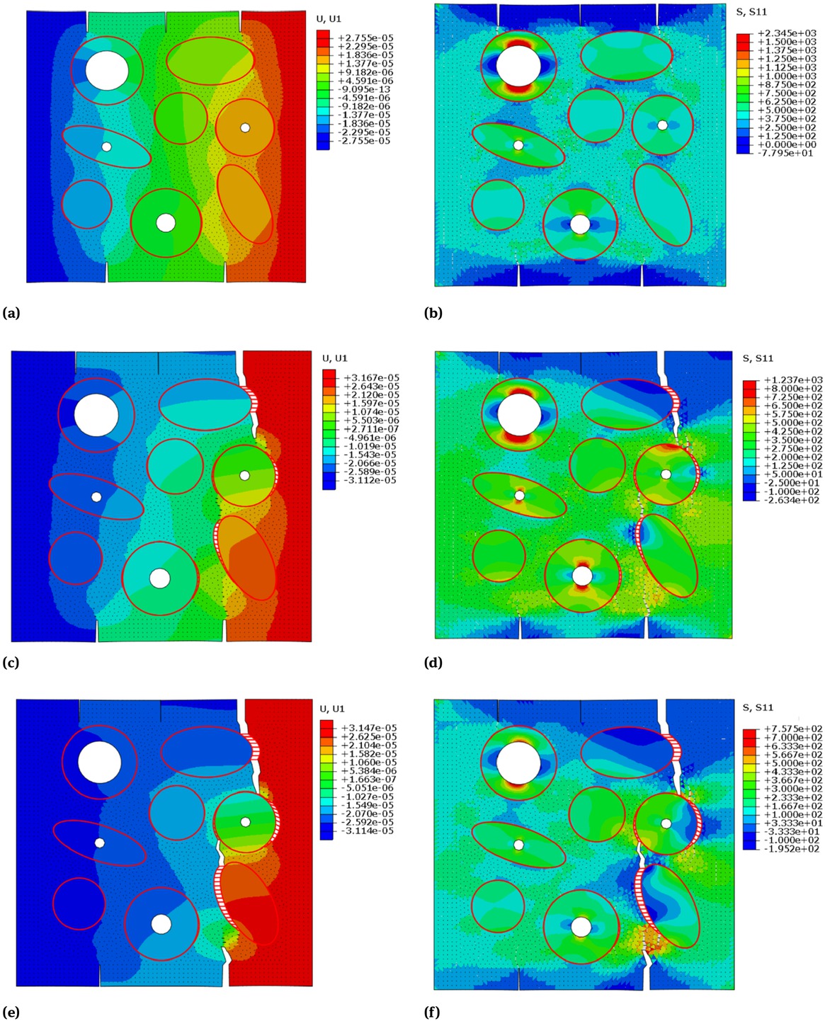
(a) (c) (e) displacement and (b) (d) (f) stress contour figures of the middle region of the cortical bone, in the cohesive FEM cracking simulation under uniform-speed displacement tension load along U1 direction.
4.3 Cracking simulation in the outer region
Figure 12 displays the simulation results of the cracking process in the outer region. Figure 12(a), (c) and (e) are displacement contour figures, and Figure 12(b), (d) and (f) are stress contour figures within the outer region while cracking. In Figure 12(a) and (b), the pre-cracking start growing under load; and a new crack generated at the interface of the interstitial bone and the layered lamellae, which coincides with “the cracks are easily to generate at the interface” shown in Figure 7(a). In Figure 12(c) and (d), when the upper pre-crack grew and reached the new crack they connected and formed a large crack, which coincides with “the micro-cracks growing in the same direction are likely to interconnect with each other” shown in Figure 8; and the lower pre-crack also showed the phenomenon that the in the interstitial bone a crack could change its growing direction, when interconnect with micro-pores or other cracks as shown in Figure 7(b). In Figure 12(e) and (f), the lower crack stopped growing when it reached a layered lamella, which coincides well with the phenomenon “cracks captured by the layered lamella” shown in Figure 8.

(a) (c) (e) displacement and (b) (d) (f) stress contour figures of the outer region of the cortical bone, in the cohesive FEM cracking simulation under uniform-speed displacement tension load along U1 direction.
5 Discussion
In this study, a long-term inplane load was applied to the cross-section of a cortical bone. Subsequently, the SEM images of different regions of the cortical bone before and after loading were observed. Based on the orientation and distribution of the cracks, the toughness of different regions was revealed. Furthermore, we established the FEM model of the middle region as well as the outer region, and using cohesive element simulated the crack generation and propagation, and compared the SEM observation and simulation result. Finally, by analysing the interaction between the cracks and the microstructures, the toughening mechanism of the cortical bone can be revealed.
5.1 Toughness of different regions
In the middle region of cortical bone, the osteons distributed evenly and randomly in the interstitial bone, with the cement line as a boundary. The cracks were mostly distributed in the interstitial bone or at the interface of the interstitial bone and the osteon along the cement line. As for the orientation of cracks, the cracks began growing in random directions, but seldom kept a straight growth. Because under the influence of the osteon, the cement line and the interstitial bone, cracks tended to change their growth directions. Based on the above phenomena, the authors concluded that the toughness of the middle region of the cortical bone is mostly the same in all directions.
In the outer region of cortical bone, the layered lamellae arranged in parallel with each other and distributed orderly in the interstitial bone. The cracks were mostly distributed in the interstitial bone, at the interface of the interstitial bone and the layered lamellae, or along the lacunas in the center of the layered lamellae. As for the orientation of cracks, few cracks changed their direction of growth in large angles. The cracks perpendicular to the layered lamellae were large in quantity but short in length, while the cracks parallel to the layered lamellae were small in quantity but long in length. In addition, the cracks with length more than 100 microns only appeared parallel to the layered lamellae. Based on the above phenomena, the authors concluded that the outer region of the cortical bone has an anisotropic toughness, besides the toughness parallel to the layered lamellae was much higher than that perpendicular to the layered lamellae.
The authors compared the toughness of the middle region and that of the outer region, with a comparative analysis of Figure 3 and Figure 7(a). Based on the fact that in the middle region, cracks longer than 100 microns appeared in all directions; while in the outer region, such cracks only appeared in the direction parallel to the layered lamellae. However, the number of over-100-micron cracks with the direction parallel to the layered lamellae in the outer region, is much larger than the whole number of over-100-micron cracks in the middle region. The authors concluded that the toughness of the outer region perpendicular to the layered lamellae, excels the average toughness of the middle region while the average toughness of the middle region excels the toughness of the outer region parallel to the layered lamellae.
5.2 Toughening mechanism of cortical bone
Through the observation of the typical microstructures in different regions and the discussion of the toughness in different regions, it is not difficult to draw a conclusion that the microstructures of cortical bone affects its toughness. The toughening mechanism of typical microstructures in cortical bone such as interstitial bone, osteon, cement lines, layered lamellae and micro-pore is discussed here.
5.2.1 Interstitial bone
Interstitial bone, form by closely arranged but randomly oriented interstitial lamellae arrays, is the main distribution area of cracks in both middle and outer regions. However, according to Figure 4, Figure 5, Figure 11 and Figure 12 the interstitial bone also has unique toughening mechanisms, which would be discussed from two perspectives.
5.2.1.1 Change of crack growth direction
Firstly, when a crack changing the growing direction, as shown in Figure 11 and Figure 4, the current stress field at the crack tip would change. The process of stress field changing would reduce the stress intensity factor and increase the structure resistance to crack growth.
Secondly, when the crack deflected, the phenomenon of "bone plate fracture" could occur, as shown in Figure 4 at the left end of the crack. A segment of the tightly arranged lamellae array break with the deflection of the crack, which not only has to overcome the cohesive forces between the interstitial lamellae, but also has to structurally destroy layers of the interstitial lamellae. Thus the energy consumption is a lot more compared with a straight crack.
5.2.1.2 Internal microstructure of the interstitial lamellae
The interstitial lamella is a splint structure formed by braiding arrangement of mineralized fibers. When a crack grew in the interstitial lamellae array, the phenomena of “fibers pull-out”, “fibers bridging”, and “fibers breaking” would happen, as shown in Figure 5. The fibers that make up the interstitial lamellae are tightly bonded. All these phenomena would consume the energy of crack and effectively inhibit the expansion and growth of the crack.
5.2.2 Osteon and cement line
Osteons, always surrounded by the cement line, are the representative microstructures of the middle region of cortical bone. The toughness of the cement line is less than that of the interstitial bone and osteon. Therefore, when a crack growing and contacting the cement line, it would have a tendency to grow along the cement line, in which direction the stress intensity factor is minimum. Since the cement line is rarely straight, the crack would keep changing the growth direction, leading to a greatly increased the energy consumption. Thus, although the cement line is less tough than the interstitial bone and the osteon, it can still improve the overall toughness of cortical bone.
When a crack was absorbed by an osteon, it passed through the interface between the cement line and the osteon, and pierced across several layers of Haversian lamellae. Accompanied with the structurally broken of these Haversian lamellae, the crack would consume a lot of energy in a very short growth distance within the osteon. This is an omni-direction toughening mechanism of the osteon.
5.2.3 Layered lamellae
Layered lamellae is the representative microstructure in the outer region of cortical bone, which is arranged parallel with each other and distributed in the interstitial bone. The layered lamellae has major influence on the anisotropic toughness of the outer region. Therefore, the toughening mechanisms of the layered lamellae are analyzed in different directions, respectively.
5.2.3.1 Toughening mechanism in the direction parallel to load
When subjected to loads parallel to the layered lamellae, cracks perpendicular to the layered lamellae would generate and grow. these cracks would pierce through several layers of the closely arranged lamellae. The structurally broken of every single lamella is accompanied with high energy consumption. Therefore, the layered lamellae have remarkable toughing effect in the direction parallel to load.
5.2.3.2 Toughening mechanism in the direction perpendicular to load
Under the load perpendicular to the layered lamellae, cracks parallel to the layered lamellae would generate and grow, always at the interface between layered lamellae and interstitial bone. The main toughening mechanisms at the interface is crack deflection. However, the arc of the interface is usually small. Therefore, the cracks have no trend of deflecting continually or deflecting to a large angle. In addition, "fibers pull out", "fibers bridging" and "fibers breaking" phenomena will also happen at the interface, which can help with the structure toughening to some extent. It can be seen that the toughening effect of layered lamellae perpendicular to load is far less than that parallel to load
5.2.4 The micro-pore
The micro-pore, with a size of about 10 microns, is widely distributed in cortical bone, functioning mainly in biological aspects, such as providing channels for blood vessels and accommodating osteocytes. In this study, we found the micro-pores could also influence the toughness.
The toughness of the interface between the micro-pore and its surrounding is much lower than that of other microstructures in cortical bone. When a crack is approaching the micro-pore, it would tend to enter the micro-pore, and redistribute energy at the micro-pore inner interface. Therefore, with high energy micro cracks could develop into large cracks by continuously penetrating and connecting several micro-pores in the same direction, as indicated by the white arrow 2 in Figure 7 (a). From this point, the micro-pore reduces the toughness of the cortical bone.
However, because of the irregular shape of the micropore and the changing of ambient microstructures, the toughness along the interface varies. Thus, as shown in the white dotted line frame in Figure 7 (b), the crack may change its growth direction after penetrating the micropore, which will consume additional energy for the crack propagation. In addition, if the energy is not enough for the micro crack to destroy the micro-pore boundary after the redistribution, the micro crack would be captured by the micro-pore, as indicated by the white arrow 2 in Figure 8. Under these circumstances, the micro-pores exert a positive influence on the toughness.
In a word, the micro-pore will exert complex influence on the toughness of the cortical bone, which is closely related to the size and distribution of the micro-pore, as well as the loading on the structure.
6 Conclusions
In this study, the cross section of cortical bone from a goat tibia was subjected to a long-term inplane load, applied by a polishing machine. The microstructures in different regions before loading, and the properties of cracks in different regions after loading were observed with SEM. Then, using cohesive FEM modelling the crack generation and propagation in different region of the cortical bone were simulated on ABAQUS. Therefore, the main toughening mechanisms in cortical bone were determined by studying the interaction between cracks and the typical microstructures.
The authors conclude that in the middle region of the cortical bone, the cortical bone is effectively toughened in all directions, mainly by the microstructure of onston and cement line. While in the outer region of the cortical bone, the toughness in the direction parallel to the layered lamellae far excels that perpendicular to the layered lamellae,which mainly due to the toughening mechanism of the layered lamellae. And from the comparison of the cohesive FEM simulation results and the SEM observation, the authors numerically verified parts of those toughening mechanism, and also proved the cohesive FEM modelling could be a powerful tool for the biological materials or structures design.
To recapitulate, the toughness mechanism of the cortical bone is revealed, verified and connected with typical micro-structural characteristics. These provide references for the design of bionic materials or structures with outstanding toughness.
Acknowledgement
The authors gratefully acknowledge the SEM supports for this work from the Institute of Light Alloy at Central South University. We also thank Kangqi Sun (Jibo Biotechnology Company) and Yongxiang Shen (Advanced optical manufacturing laboratory of National University of Defense Technology) for their considerable assistance in sample preparation and treatment.
References
[1] Bažant, Z.P.; Chen, E. Scaling of Structural Failure. Advances in Mechanics 1999, 50, 593-627.10.1115/1.3101672Search in Google Scholar
[2] Mohsin, S.; O’Brien, F.J.; Lee, T.C. Osteonal crack barriers in ovine compact bone. J ANAT 2010, 208, 81-89.10.1111/j.1469-7580.2006.00509.xSearch in Google Scholar
[3] Rho, J.Y.; Kuhnspearing, L.; Zioupos, P. Mechanical properties and the hierarchical structure of bone. MED ENG PHYS 1998, 20, 92.10.1016/S1350-4533(98)00007-1Search in Google Scholar
[4] Meyers, M.A.; Chen, P.Y. Structural biological materials: critical mechanics-materials connections. SCIENCE 2013, 339, 773-779.10.1126/science.1220854Search in Google Scholar
[5] O Brien, F.J.; Taylor, D.; Lee, T.C. The effect of bone microstructure on the initiation and growth of microcracks.. J ORTHOP RES 2005, 23, 475-480.10.1016/j.orthres.2004.08.005Search in Google Scholar
[6] Sabet, F.A.; Raeisi, N.A.; Hamed, E.; Jasiuk, I. Modelling of bone fracture and strength at different length scales: a review. INTERFACE FOCUS 2016, 6, 20150055.10.1098/rsfs.2015.0055Search in Google Scholar
[7] Ji, B.; Gao, H. Mechanical properties of nanostructure of biological materials. Journal of the Mechanics & Physics of Solids 2004, 52, 1963-1990.10.1016/j.jmps.2004.03.006Search in Google Scholar
[8] Gao, H. Mechanical Principles of a Self-Similar Hierarchical Structure. INT J SOLIDS STRUCT 2007, 44, 8177-8193.10.1557/PROC-1188-LL01-01Search in Google Scholar
[9] Jäger I, Fratzl P. Mineralized collagen fibrils: a mechanical model with a staggered arrangement of mineral particles. Biophys. J. 2000, 79, 1737–1746.10.1016/S0006-3495(00)76426-5Search in Google Scholar
[10] Najafi, A.R.; Arshi, A.R.; Eslami, M.R.; Fariborz, S.; Moeinzadeh, M.H. Micromechanics fracture in osteonal cortical bone: A study of the interactions between microcrack propagation, microstructure and the material properties. J BIOMECH 2007, 40, 2788-2795.10.1016/j.jbiomech.2007.01.017Search in Google Scholar PubMed
[11] Ural, A. Cohesive modeling of bone fracture at multiple scales. Procedia Engineering 2011, 10, 2827-2832.10.1016/j.proeng.2011.04.470Search in Google Scholar
[12] Ural, A.; Mischinski, S. Multiscale modeling of bone fracture using cohesive finite elements. ENG FRACT MECH 2013, 103, 141-152.10.1016/j.engfracmech.2012.05.008Search in Google Scholar
[13] Siegmund T, Allen MR, Burr DB. Failure of mineralized collagen fibrils: Modeling the role of collagen cross-linking. J. Biomech. 2008, 41, 1427–1435.10.1016/j.jbiomech.2008.02.017Search in Google Scholar PubMed
[14] Siegmund T, Allen MR, Burr DB. Modeling of bone failure by cohesive zone models. In Proc. 22nd Int. Congress of Theoretical and Applied Mechanics, Adelaide, Australia, 24–29 August 2008, pp. 217–230. Dordrecht, The Netherlands: Springer10.1007/978-94-007-5968-8_14Search in Google Scholar
[15] Luo Q, Nakade R, Dong X, Rong Q. Effect of mineral–collagen interfacial behavior on the microdamage progression in bone using a probabilistic cohesive finite element model. J. Orthop. 2011, Res. 4, 943–952.10.1016/j.jmbbm.2011.02.003Search in Google Scholar PubMed
[16] Barkaoui A , Hambli R . Nanomechanical properties of mineralised collagen microfibrils based on finite elements method: biomechanical role of cross-links[J]. Computer Methods in Biomechanics and Biomedical Engineering, 2014, 17(14):1590-1601.10.1080/10255842.2012.758255Search in Google Scholar PubMed
[17] Li, S.; Abdel-Wahab, A.; Demirci, E.; Silberschmidt, V.V. Fracture process in cortical bone: X-FEM analysis of microstructured models. INT J FRACTURE 2013, 184, 43-55.10.1007/978-3-319-04397-5_5Search in Google Scholar
[18] Budyn E, Hoc T. Multiscale modeling of human cortical bone: aging and failure studies. Mater. Res. Soc. Symp. Proc. 2006, 975, 27–32.10.1557/PROC-975-0975-DD02-06Search in Google Scholar
[19] Budyn E, Hoc T, Jonvaux J. Fracture strength assessment and aging signs detection in human cortical bone using an X-FEM multiple scale approach. Comput. Mech. 2008, 42, 579–591.10.1007/s00466-008-0283-1Search in Google Scholar
[20] Budyn E’, Jonvaux J, Funfschilling C, Hoc T. Bovine cortical bone stiffness and local strain are affected by mineralization and morphology. J. Appl. Mech. 2012, 79, 011008.10.1115/1.4004644Search in Google Scholar
[21] Georgiadis, M.; Müller, R.; Schneider, P. Techniques to assess bone ultrastructure organization: orientation and arrangement of mineralized collagen fibrils. J R SOC INTERFACE 2016, 13, 20160088.10.1098/rsif.2016.0088Search in Google Scholar PubMed PubMed Central
[22] Katsamenis, O.L.; Jenkins, T.; Thurner, P.J. Toughness and damage susceptibility in human cortical bone is proportional to mechanical inhomogeneity at the osteonal-level. BONE 2015, 76, 158-168.10.1016/j.bone.2015.03.020Search in Google Scholar PubMed
[23] Barkaoui, A.; Hambli, R.; Tavares, J.M. Effect of material and structural factors on fracture behaviour of mineralised collagen microfibril using finite element simulation. Comput Methods Biomech Biomed Engin 2015, 18 1181-1190.10.1080/10255842.2014.883601Search in Google Scholar PubMed
[24] Faingold, A.; Cohen, S.R.; Reznikov, N.; Wagner, H.D. Osteonal lamellae elementary units: lamellar microstructure, curvature and mechanical properties. ACTA BIOMATER 2013, 9, 5956-5962.10.1016/j.actbio.2012.11.032Search in Google Scholar PubMed
© 2020 X. Wang et al., published by De Gruyter
This work is licensed under the Creative Commons Attribution 4.0 International License.
Articles in the same Issue
- Regular Articles
- Microstructure and compressive behavior of lamellar Al2O3p/Al composite prepared by freeze-drying and mechanical-pressure infiltration method
- Al3Ti/ADC12 Composite Synthesized by Ultrasonic Chemistry in Situ Reaction
- Microstructure and photocatalytic performance of micro arc oxidation coatings after heat treatment
- The effect of carbon nanotubes on the mechanical and damping properties of macro-defect-free cements
- Toughening Mechanism of the Bone — Enlightenment from the Microstructure of Goat Tibia
- Characterization of PVC/MWCNTs Nanocomposite: Solvent Blend
- Study on Macroscopic and Mesoscopic Mechanical Behavior of CSG based on Inversion of Mesoscopic Material Parameters
- Bearing properties and influence laws of concrete-filled steel tubular arches for underground mining roadway support
- Comparing Test Methods for the Intra-ply Shear Properties of Uncured Prepreg Tapes
- Investigation of Microstructural, Mechanical and Corrosion Properties of AA7010-TiB2 in-situ Metal Matrix Composite
- A Comparative Study of Structural Changes in Conventional and Unconventional Machining and Mechanical Properties Evaluation of Polypropylene Based Self Reinforced Composites
- Research on Influence mechanism of composite interlaminar shear strength under normal stress
- Mechanical properties of geopolymer foam at high temperature
- Synthesis and mechanical properties of nano-Sb2O3/BPS-PP composites
- Multiscale acoustic emission of C/SiC mini-composites and damage identification using pattern recognition
- Modifying mechanical properties of Shanghai clayey soil with construction waste and pulverized lime
- Relationship between Al2O3 Content and Wear Behavior of Al+2% Graphite Matrix Composites
- Static mechanical properties and mechanism of C200 ultra-high performance concrete (UHPC) containing coarse aggregates
- A Parametric Study on the Elliptical hole Effects of Laminate Composite Plates under Thermal Buckling Load
- Morphology and crystallization kinetics of Rubber-modified Nylon 6 Prepared by Anionic In-situ Polymerization
- Effects of Elliptical Hole on the Correlation of Natural Frequency with Buckling Load of Basalt Laminates Composite Plates
- Effect of interphase parameters on elastic modulus prediction for cellulose nanocrystal fiber reinforced polymer composite
- Mixed Matrix Membranes prepared from polysulfone and Linde Type A zeolite
- Fabrication and low-velocity impact response of pyramidal lattice stitched foam sandwich composites
- Design and static testing of wing structure of a composite four-seater electric aircraft
- CSG Elastic Modulus Model Prediction Considering Meso-components and its Effect
- Optimization of spinning parameters of 20/316L bimetal composite tube based on orthogonal test
- Chloride-induced corrosion behavior of reinforced cement mortar with MWCNTs
- Statistical Law and Predictive Analysis of Compressive Strength of Cemented Sand and Gravel
- Young’s modulus and Poisson’s ratio of the deformable cement adhesives
- Reverse localization on composite laminates using attenuated strain wave
- Impact of reinforcement on shrinkage in the concrete floors of a residential building
- Novel multi-zone self-heated composites tool for out-of-autoclave aerospace components manufacturing
- Effect of notch on static and fatigue properties of T800 fabric reinforced composites
- Electrochemical Discharge Grinding of Metal Matrix Composites Using Shaped Abrasive Tools Formed by Sintered Bronze/diamond
- Fabrication and performance of PNN-PZT piezoelectric ceramics obtained by low-temperature sintering
- The extension of thixotropy of cement paste under vibration: a shear-vibration equivalent theory
- Conventional and unconventional materials used in the production of brake pads – review
- Inverse Analysis of Concrete Meso-constitutive Model Parameters Considering Aggregate Size Effect
- Finite element model of laminate construction element with multi-phase microstructure
- Effect of Cooling Rate and Austenite Deformation on Hardness and Microstructure of 960MPa High Strength Steel
- Study on microcrystalline cellulose/chitosan blend foam gel material
- Investigating the influence of multi-walled carbon nanotubes on the mechanical and damping properties of ultra-high performance concrete
- Preparation and properties of metal textured polypropylene composites with low odor and low VOC
- Calculation Model for the Mixing Amount of Internal Curing Materials in High-strength Concrete based on Modified MULTIMOORA
- Electric degradation in PZT piezoelectric ceramics under a DC bias
- Cushioning energy absorption of regular polygonal paper corrugation tubes under axial drop impact
- Erratum
- Study on Macroscopic and Mesoscopic Mechanical Behavior of CSG based on Inversion of Mesoscopic Material Parameters
- Effect of interphase parameters on elastic modulus prediction for cellulose nanocrystal fiber reinforced polymer composite
- Statistical Law and Predictive Analysis of Compressive Strength of Cemented Sand and Gravel
- Retraction
- Assessment of nano-TiO2 and class F fly ash effects on flexural fracture and microstructure of binary blended concrete