
Efficiency of CFRP torsional strengthening technique for L-shaped spandrel reinforced concrete beams
-
Noor Ayaad


Abstract
The present study aims to get experimentally a deeper understanding of the efficiency of carbon fiber-reinforced polymer (CFRP) sheets applied to improve the torsional behavior of L-shaped reinforced concrete spandrel beams in which their ledges were loaded in two stages under monotonic loading. An experimental program was conducted on spandrel beams considering different key parameters including the cross-sectional aspect ratio (i.e., web height/web thickness), and the availability of the CFRP strengthening system. The ledge of the spandrel beams was exposed during testing to a very high eccentric load, which was transferred to the web of the spandrel beam causing high shear, torsion, and bending moments. Consequently, the applied load resulted in in-plane and out-of-plane deformations of the web accompanied by flexural and shear cracks. This article demonstrates the advantage of using CFRP sheets to strengthen the mentioned members. The applied CFRP sheets increased the failure torsional load by about 37% compared to the identical L-spandrels without strengthening. The outcomes indicate that using CFRP sheets show improvement in restricting the deflections and rotation of L-spandrels due to increasing spandrel stiffness. The reduction in the degree of rotation attained more than 33% in comparison to the spandrel beams without strengthening. The experimental program confirmed the applicability of the proposed strengthening technique for compacted and slender L-shaped spandrel-reinforced concrete beams.
1 Introduction
L-shaped spandrel members are often subjected to a series of vertical eccentric loadings when used in parking structures and abutments of bridges to transfer heavy loads from double-tee decks to columns, see Figure 1 [1]. The mentioned loads developed torsion in these structural members at the end regions. Designs commonly require perpendicular closed stirrups terminated by 135° standard hooks ACI 318-19 [2]. The required reinforcement for spandrel members, as required by international codes [2,3] is generally designed according to a general procedure originally proposed by Zia and McGee [4] and later modified by Zia and Hsu [5].
![Figure 1
L-shaped slender spandrel [1].](/document/doi/10.1515/jmbm-2022-0243/asset/graphic/j_jmbm-2022-0243_fig_001.jpg)
L-shaped slender spandrel [1].
Ali [6] investigated the influence of the amounts of longitudinal steel reinforcement, transverse steel reinforcement, and the concrete strength on 18 floor-spandrel beam assembly to determine the ultimate flexural load, torsional, and deformation capacities. The torsional resistance prior to cracking is affected by the ratio of bending moment to twisting moment, section geometry, and the concrete tensile strength. The ultimate torsional strength based on the skew bending theory is dependent on the concrete and steel stress–strain relationships, the ratio of the bending moment to twisting moment, section properties, and the amount of steel provided. When shear is present the torsional strength in addition to the above factors is also influenced by the shear to torsion ratio. Observations of spandrel members in the laboratory and the field by Raths [7], Klein [8], and Logan [9] detected that the failure planes of the compact and slender spandrels were the same, with out-of-plane bending causing web diagonal cracking growing upward from its end regions.
Salom et al. [10] studied both experimental and analytical programs of six L-shaped beams. Two beams were considered as control specimens, the other four specimens were strengthened with carbon fiber-reinforced polymer (CFRP) laminate. This study focused on the effect of strengthening on the torsional and shear capacity of beams when the ends of the specimen are exposed to pure twisting force. This study showed that the CFRP laminates could increase the torsional capacity of beams by more than 70%. A good agreement between experimental and analytical results was found. Hassan et al. [11] and Walter [12] investigated full-scale slender L-shaped spandrel precast concrete beams. Their study confirmed experimentally and numerically by finite element analysis that the open web stirrups could be used safely and effectively. Lucier et al. [1,13] developed rational design guidelines for L-shaped spandrel precast concrete beams depending on experimental testing and finite element analysis. These guidelines assumed the torque could be analyzed into two orthogonal components acting on an angle of 45° failure plane (Figure 2). The plate-bending component
![Figure 2
Torsion components on a cross-section [13].](/document/doi/10.1515/jmbm-2022-0243/asset/graphic/j_jmbm-2022-0243_fig_002.jpg)
Torsion components on a cross-section [13].
Although several studies on L-shaped spandrel beams have been conducted in the past decades, studies on the spandrel beams strengthening loaded under two stages are uncommon. In terms of the influence of the externally bonded CFRP sheets on the torsional behavior of spandrel beams, no studies have been conducted yet. Therefore, this study aims to get experimentally a deeper understanding of the efficiency of CFRP sheets applied to improve the torsional behavior of L-shaped reinforced concrete spandrel beams in which their ledges were loaded in two stages under monotonic loading.
2 Experimental program
The experimental program consists of testing four simply supported L-shaped reinforced concrete beams under eccentric single load at ledge mid-span to study various limit state behaviors, including two stages of loadings. In stage 1, the load was applied up to the level corresponding to 60% of yielding stress in the vertical steel stirrup at the web mid-span section followed by an unloading process up to zero level. In other words, the strengthening installation on already cracked and laterally deflected spandrel beams that are within the serviceability limits will be evaluated in this stage. In stage 2, the test specimen was exposed to reloading up to the failure level. Two beams were tested as control specimens without strengthening, while the others were retrofitted with CFRP sheets.
2.1 Test matrix of spandrel beams
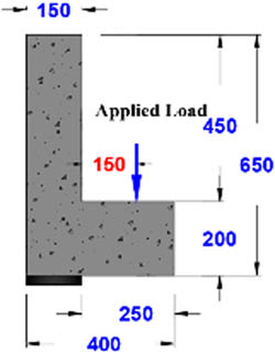
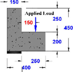
The aspect ratio of the spandrel beam is defined as the ratio of the web height to web thickness (h/t). In the present study, two aspect ratios were adopted to be investigated for the designed spandrel beams, mainly 4.3 and 3.0, which represent slender and compact sections, respectively. The identical cross-sections of the slender and compact beams had web dimensions of 650 mm × 150 mm and 450 mm × 150 mm, respectively, with ledge dimensions of 250 mm × 200 mm. All tested beams had a span of 1,500 mm. While the ledge was cut back for 150 mm on either end of the spandrel to simulate an idealistic field conditions detail that allows the typical web to be connected to supporting columns. Each side of the web was provided with two holes over through the thickness to achieve connection with the vertical rigid frame assembly with high-strength threaded rods, as idealistic field conditions. The concrete strength of each spandrel was based on the average strength of three cylinders (150 mm × 300 mm) tested in conformity with ASTM C39 [17]. Three samples of each steel bar with 500 mm length and diameters of ∅ 10, ∅ 12, and ∅ 16 mm were tested. The ASTM A370-19 [18] was used to evaluate the yield tensile strength and ultimate tensile strength of steel bars. Table 1 summarizes the properties of spandrel beams, while the results of reinforcing steel bars are listed in Table 2.
Properties of spandrel beams
| Group | Spandrels designation | Aspect ratio | Strengthening status | Cylinder concrete strength (MPa) | Cross-sectional configuration |
|---|---|---|---|---|---|
| I | SB1-US-S | 4.3 | Unstrengthen | 43.2 |
|
| SB1-CS-S | 4.3 | Strengthened | 44.0 | ||
| II | SB2-US-S | 3.0 | Unstrengthen | 45.0 |
|
| SB2-CS-S | 3.0 | Strengthened | 41.6 |
Mechanical properties of steel reinforcement
| Nominal diameter (mm) |
|
|
Elongation (%) |
|---|---|---|---|
| Ø 10 | 575.00 | 670.67 | 9.34 |
| Ø 12 | 605.05 | 698.00 | 9.42 |
| Ø 16 | 612.67 | 707.00 | 11.18 |
2.2 Reinforcement details
The modified design procedure remained unchanged in PCA Notes on ACI 318-11 [19]. It should be noted that there were no updates on the PCA notes for ACI 318-14 and ACI 318-19. Therefore, all spandrel beams in this study were fabricated according to PCA Notes on ACI 318-11 and the eighth edition of the PCI Design Handbook assuming that the outer branches of closed vertical stirrups are resisting torsion stress and acting as a hanger for the ledge. Thus, all spandrels were designed to resist shear–torsion distress, and twist loadings according to the latest revision of the ACI 318 code. In this investigation, to assure end-region failures, additional flexural and ledge reinforcement was provided. Also, the ledge punching shear (localized failures) must be considered and prevented to transfer the load from the ledge to the spandrel web by using extra reinforcement. The spandrels had one configuration of shear and torsion reinforcement, which was available in the frontal and back web faces. Conventional deformed steel reinforcement was used to resist the bending, shear, and torsion combination that was induced in each spandrel. Figure 3 shows the reinforcement configurations used to test spandrels SB1-US-S and SB1-CS-S.
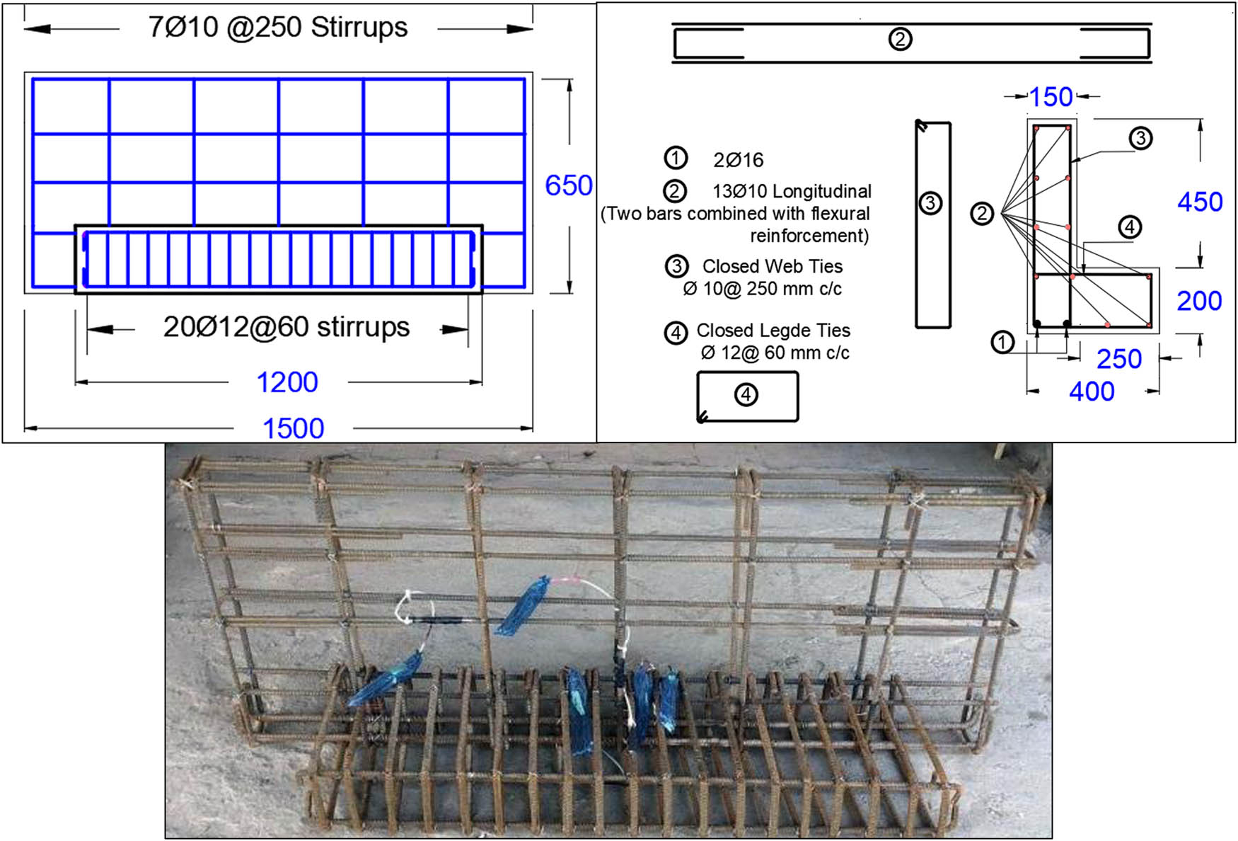
Reinforcement details for tested spandrels of group I (all dimensions are in mm).
2.3 Test setup
The loading frame used to test both slender and compact spandrel beams was the same, which applied a single point loading at the mid-span section of the ledge with a distance of 150 mm from the frontal face of the web. The supporting system was designed to include specially built assemblies to transfer the spandrel beam end reactions to the loading frame and, consequently, to the rigid floor with minimal support yielding and to prevent spandrel overturning or sliding during testing. These spandrel beams were tested in a simply supported scheme at the ends over an effective span of 1,300 mm and were rested on steel plates of 100 mm × 150 mm dimensions, centered relative to the spandrel web, through which the vertical components of reactions were transferred.
Two load cells with a capacity of 500 kN were used to determine the vertical component of the reaction, one per end located at the center of the web. Two main advantages of these load cells, mainly were monitor and record the value of the reaction at the position of influence; and determine how the influence point of the reaction was shifted relative to the web of the spandrel during the process of testing. Each spandrel was supported laterally by the restraining of the web at both ends. Vertical rigid assemblies were provided at the back of the web using stiff steel channels attached to the back face of the spandrel’s web with two heavy threaded rods, at each end, inserted over through the created web holes that were accurately positioned during casting. The vertical rigid assembly was used to restrain the movement of the test specimen and to provide torsional restraint at the web ends. To capture the lateral forces in the threaded rod, other load cells were placed at the top of the web’s frontal face and the bottom of the web’s back face. Figure 4 shows a profile of the test setup while the photograph of the completed test setups is shown in Figure 5.
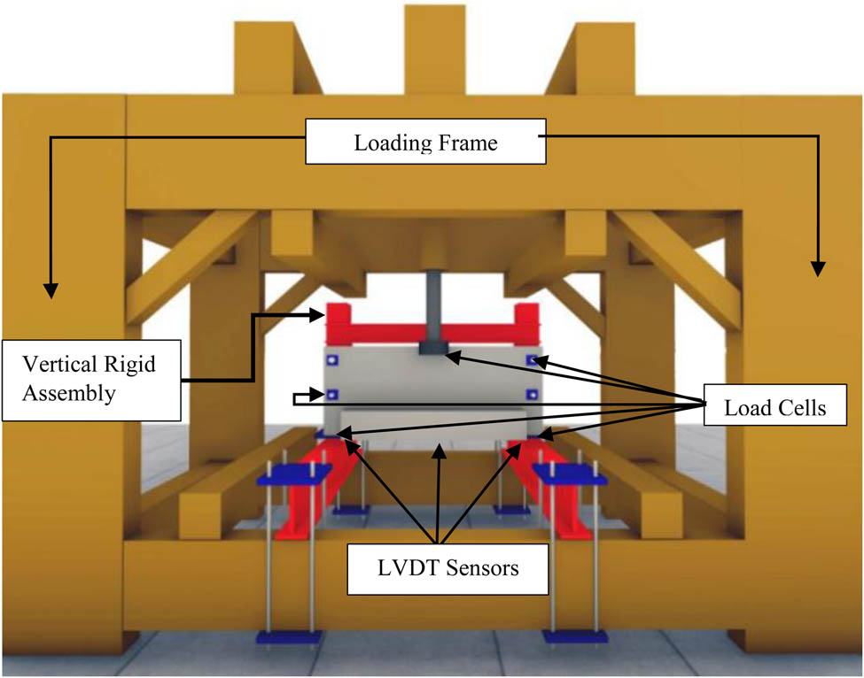
Profile of the test setup.
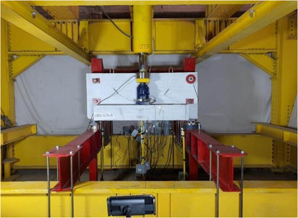
Typical test setup.
2.4 Loading sequence and strengthening implementation
The control spandrel beam (unstrengthened) was exposed to monotonic static loading in steps up to the level that achieved stress in the vertical steel stirrup at the web’s mid-span section of 60%
The scenario of testing the strengthened spandrel beams was the same as for the control beam during stages 1 and 2 except that, before starting the reloading stage, the spandrel beam was strengthened with externally bonded CFRP sheets which were applied to the frontal and back faces of the web and on the soffit of the tested beams.
CFRP schemes were calculated according to the requirements of the ACI 440.2R-08 code [20]. Individual CFRP strips of 150 mm width were implemented which wrapped the beam cross-section and distributed along the beam span. The CFRP ‘wet lay-up’ system consisting of a primer, CFRP sheet, and resin used applied for strengthening in this study. The primer increases the bond between the composite and the concrete substrate and it consists of two parts.
The CFRP sheets are high-performance carbon fiber supplied in unidirectional tow sheets of 500 mm in width.
The fiber thickness was reported to be 0.167 mm and its dry density was 1.8 g/cm3 with 230 GPa modulus of elasticity in tension and dry fiber tensile strength of 4,900 MPa. The installation procedure includes the following steps: (i) sandblast the bonding surfaces to remove thin layers of cement laitance adhering to the concrete surface and expose coarse aggregates to improve the connection between the CFRP strips and the concrete substrate, (ii) apply primer to the exposed concrete substrate to fill cracks and pores, (iii) cut CFRP sheet strips to 150 mm wide and 1,950 mm long for SB1-CS-S or 1,550 mm for SB2-CS-S, (iv) impregnate CFRP sheet strips with resin and place them on top of the primer, and (v) leave specimens to cure at room temperature for 7 days. After completing the CFRP fabrication and epoxy resin curing, on the eighth day, the spandrel beam was reloaded in steps to failure. Figure 6 shows the application process of the CFRP fabric while Figure 7 illustrates the loading sequence for a typical test.
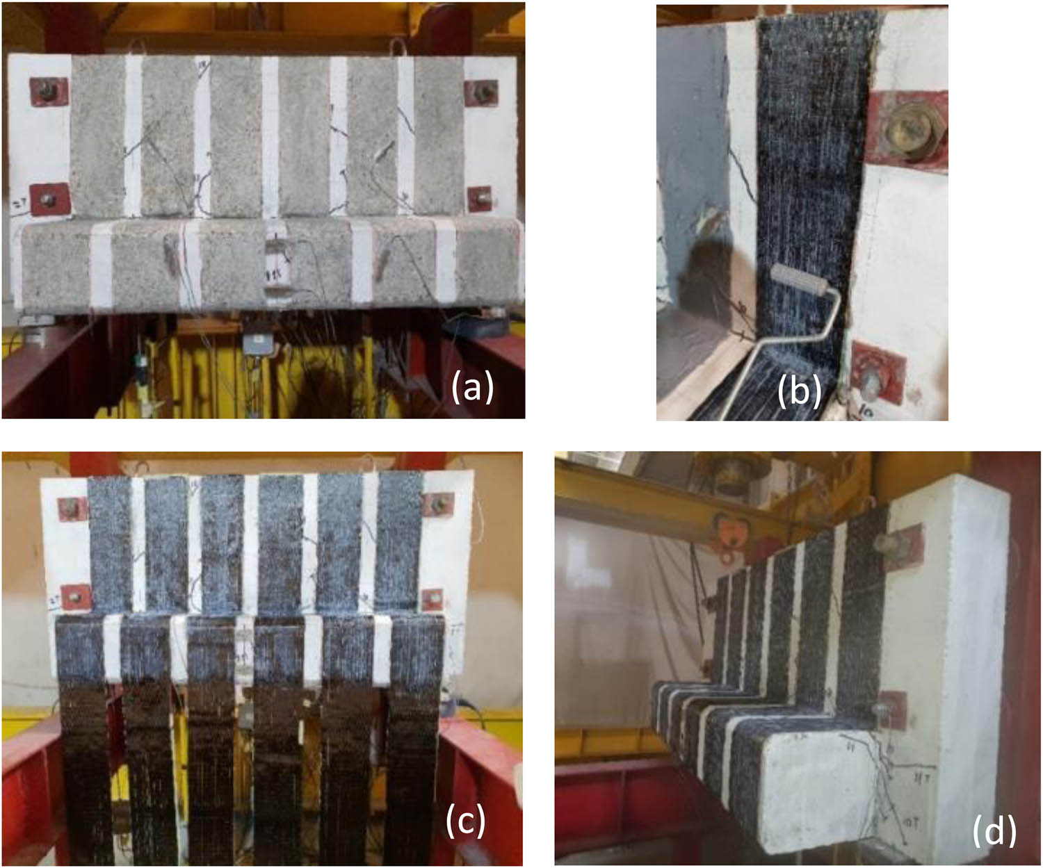
Strengthening procedure: (a) grinding of concrete, (b) application of CFRP and epoxy, (c) front face after application of CFRP, and (d) final form after the application of CFRP.
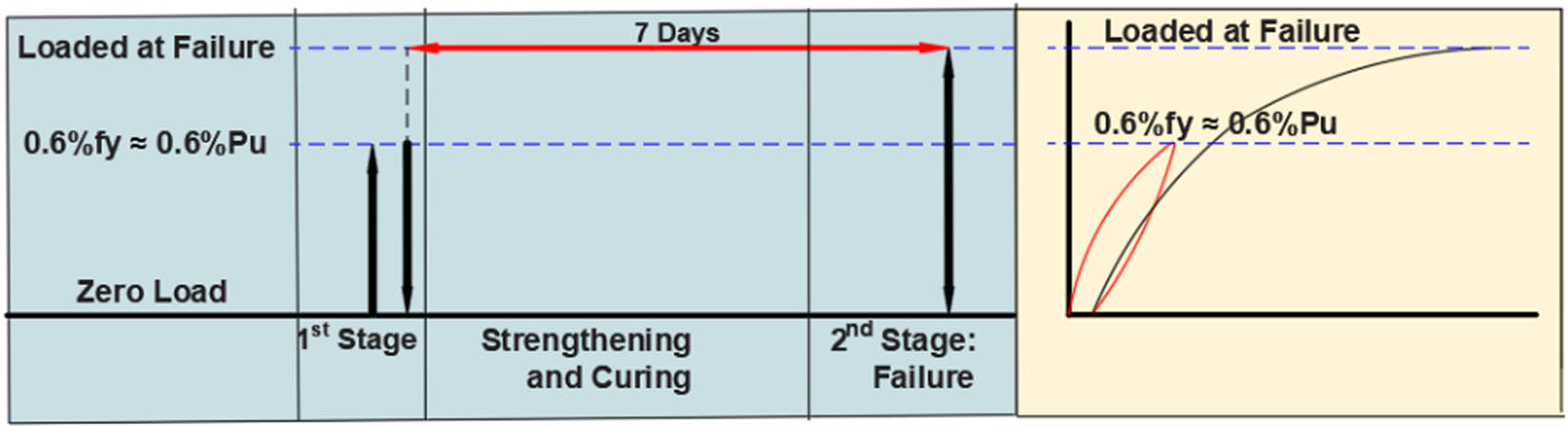
Typical loading sequence.
2.5 Instrumentation
Three types of instrumentation were used to monitor and record the applied load, reactions, strains, deflections, and rotations for all spandrels. Five load cells recorded the applied load, vertical reactions, and lateral reactions. Linear variable displacement transducers were used for recording vertical deflections and lateral deflections at various locations. Measurements of the vertical deflection were selected at the intersection line of the ledge and the web of spandrel at the mid-span section. Also, the deflections near the web ends were recorded to monitor support vertical settlement. Lateral deflections at the mid-span section were observed at the top and bottom centerline of the web’s back face to determine the rotation. Fourteen electrical resistance pre-wired strain gauges were used to measure strains in concrete, steel reinforcement, and CFRP strips. Two strain gauges were glued on the top and bottom concrete fibers of the ledge at the mid-span section (SG-8 and SG-9) and four strain gauges on the concrete fibers of the ledge and web frontal (inner) face (SG-10 to SG-13). Seven strain gauges were used to measure steel reinforcement strains at different locations in the mid-span section and the section located at 300 mm from the left edge of the ledge on the main longitudinal bars (SG-6 and SG-7), skin longitudinal bars (SG-4 and SG-5), top horizontal leg of the transverse reinforcement of the ledge (SG-1), and on vertical legs of the transverse reinforcement of the web (SG-2 and SG-3). One strain gauge served to monitor strain in CFRP sheets (SG-14). All instrumentation was connected to a computerized (NI) data acquisition device to record data automatically. The strain gauge resistances were 120 ± 0.5, 118.5 ± 0.5, and 119.5 ± 0.5 Ω for concrete, rebar, and CFRP sheet, respectively. Strain gauges type (PL-60-11-3LJC-F) with base length 60 mm, type FLAB-6-11-3LJC-F with base length 6 mm, and type BFLAB-5-3-3LJC-F with base length 5 mm were used for concrete, steel rebars, and CFRP sheets, respectively. Figure 8 illustrates the strain gauge locations.
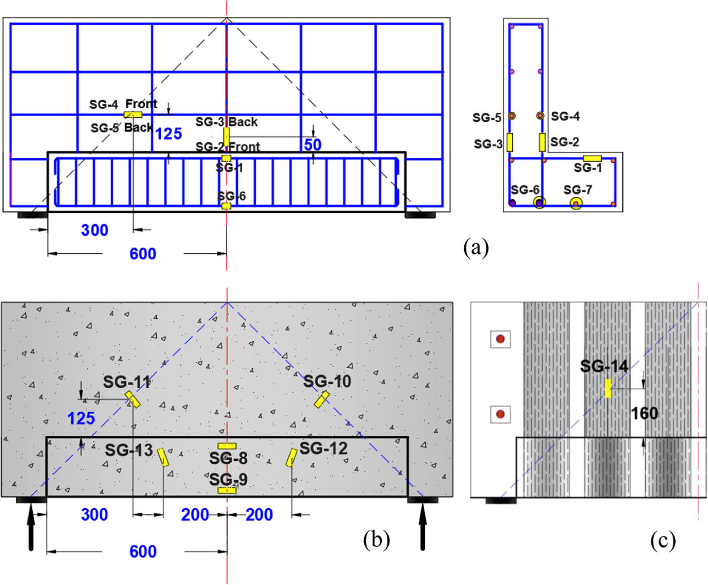
Strain gauges location on (a) rebars, (b) concrete, and (c) CFRP sheet.
3 Results and discussion
Strengthening spandrel beams were reloaded to failure after CFRP installation and completing the curing time of the epoxy resin. Table 3 summarizes the applied load at the mid-span section, vertical reactions, lateral reactions, measured deflections at failure, and degrees of rotation.
Test results of load and displacement at failure
| Specimen ID | Total applied load at mid-span (kN) | Increase of applied load (%) | Maximum vertical reactions (kN) | Maximum lateral reactions (kN) | Mid-span vertical deflection (mm) | Rotation (deg.) | ||
|---|---|---|---|---|---|---|---|---|
| Left | Right | Bottom left | Top right | |||||
| SB1-US-S | 190 | Control | 94.5 | 93.8 | 34.2 | 33.4 | 28.90 | 1.5 |
| SB1-CS-S | 260 | 37 | 127.3 | 125.5 | 46.1 | 45.6 | 25.41 | 1.0 |
| SB2-US-S | 200 | Control | 97.9 | 99.3 | 85.6 | 79.9 | 30.61 | 4.4 |
| SB2-CS-S | 276 | 38 | 135.3 | 130.5 | 123.5 | 119.3 | 28.88 | 2.8 |
3.1 Cracking pattern
During stage 1 of loading, all the tested spandrel beams showed cracks of different orientations. Commonly, light skewed cracks have appeared on the web’s frontal face of the spandrel beam while minimal flexural cracking appeared on the web’s back (outer) face near the mid-span section. Some of these cracks were closed during unloading. During stage 2 of loading, the cracking propagation was also investigated as the load increases to failure. The cracking pattern for all tested spandrels was similar.
It was noticed that the crack pattern was consistent for all specimens and agreed with what would typically be observed by Raths [7], Klein [8], and Logan [9]. The combination of shear and torsion stresses led to such a cracking pattern in a spandrel beam. It is important to note that the shear stresses and torsional distress act in the same direction in the frontal face of the web, which led to making a high traditional diagonal tension in the web’s end regions. In the web’s back face, the interaction between the principal tensile shear and torsional distress tends to negate each other. Thus, the diagonal tension on the web’s back face was reduced and could even be opposite to that on the frontal face depending on the magnitudes of the shear and torsional stresses. Diagonal cracks on the frontal face of the web were initiated from the outer corners of the ledge and propagated upward with an initial angle of approximately 45°. Moving away from the spandrel ends to the mid-span section, the crack’s angle progressively decreased and the crack changed its orientation that became parallel to the line of interaction between the web and the ledge. Vertical flexural cracks were propagated with loading upward from the soffit of the ledge around the region of the mid-span section.
At the failure stage, it was noticed that the crack width in the end regions of the control spandrels SB1-US-S and SB2-US-S was larger than that of the strengthened beams SB1-CS-S and SB2-CS-S, even though the strengthened spandrels were subjected to higher applied loading. Also, in all tested spandrels, some diagonal cracks excessively propagated on the web’s frontal face continuing their inclined growth and intersecting the top surface of the web forming skew cracks that reflected the torsion effect, see Figure 9.
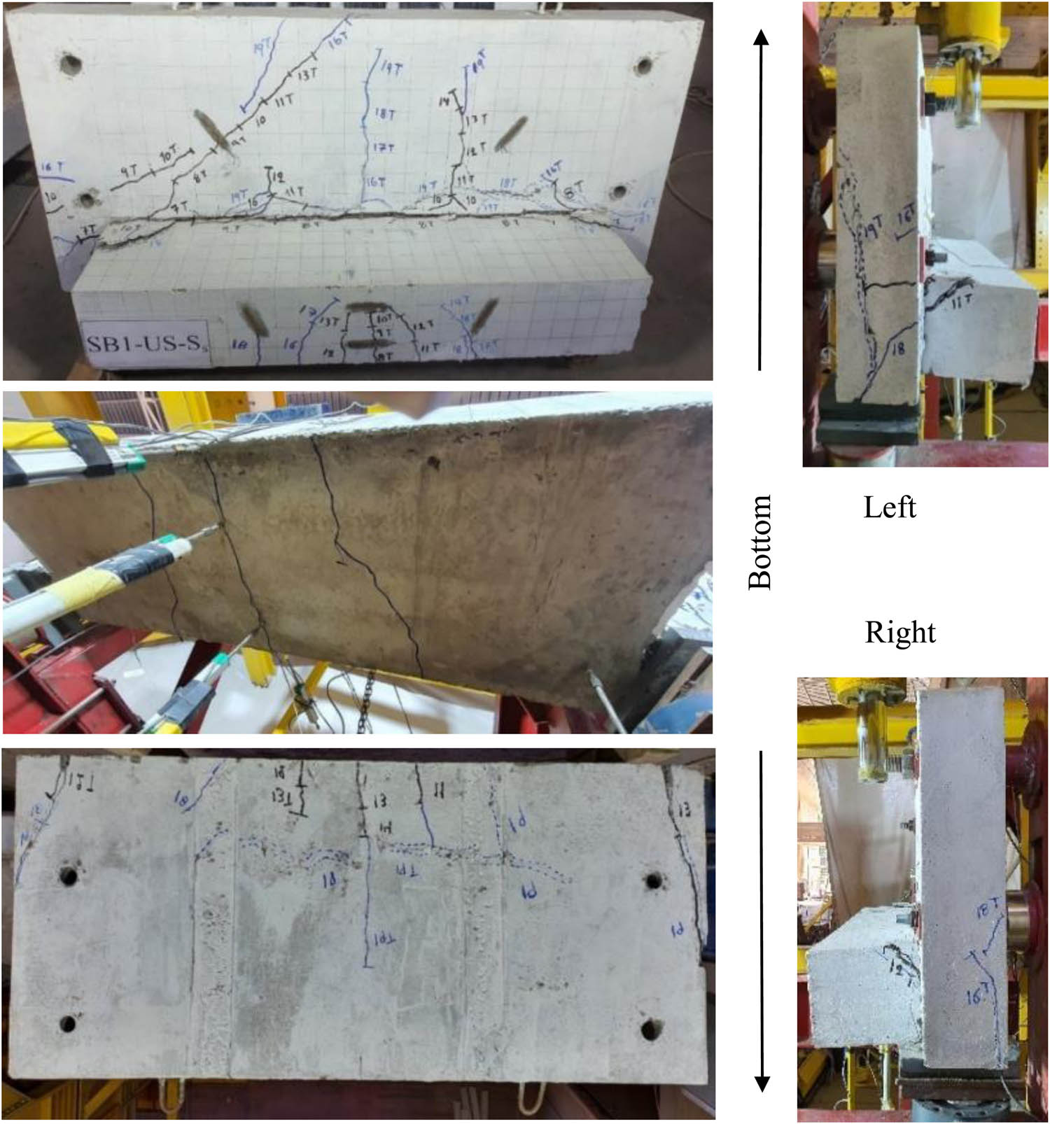
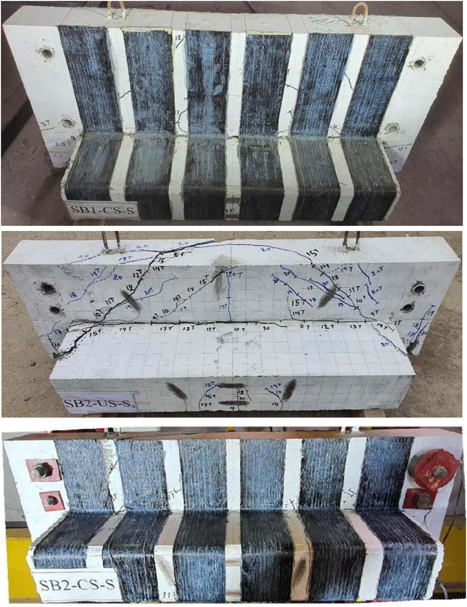
Cracking pattern and failure mechanism of L-spandrel beams.
Also, there was inclined severe cracking at 45° on the web’s inner face near the support, resulting from the out-of-plane bending induced by the end lateral couple force needed to prevent the spandrel from moving toward the applied load in response to eccentric vertical load.
The propagation of critical diagonal cracks and the cracks skewed across the top edge of the web depends on the implementation of the strengthening scheme. It was observed that the strengthened L-spandrels SB1-CS-S and SB2-CS-S had little skewed cracks across the top edge of the web in comparison to the unstrengthened L-spandrels SB1-US-S and SB2-US-S.
It was monitored that the vertical flexural cracks were dominant near the mid-span section of the L-spandrels, which initiated at the soffit of the ledge and propagated upward across the ledge’s depth. These cracks were wrapped under the soffit of the web and also linked to the flexural cracks on the back (outer) face of the web (Figure 9). Between the ends of the L-spandrel and the mid-span section, many inclined cracks were observed, reflecting the shear effect in these regions. Increasing the applied load to higher levels, the symptoms of severe spiral cracking would become evident in the control spandrels SB1-US-S and SB2-US-S end regions of the web’s faces accompanied by face–shell concrete spalling as their surfaces warp and deform under the effects of torsion distress. As would be expected, the L-spandrels SB1-CS-S and SB2-CS-S showed the efficiency of the CFRP strengthening system, especially at the ends of the interaction line between the web and the ledge, which led to preventing the spalling of concrete and limiting the overall deformation.
3.2 Failure modes
Failure modes of end-regions are shown in Figure 9 for all tested L-spandrel beams. It is important to remember that spandrels were designed in such a way to prevent premature ledge localized failure or flexure failure by providing extra ledge reinforcement and web flexural reinforcement. All the four L-spandrels showed the same failure mode including moderate diagonal cracking on the web’s frontal face and moderate flexural cracking on the web’s back face at the first stage. At the failure stage, the spandrel’s failure modes began to differ depending on the availability of the CFRP strips.
As would be planned, localized failures did not occur during the testing of all spandrel beams. Both of the spandrels SB1-US-S and SB2-US-S failed in their end regions due to a global skew-bending mechanism in combination with vertical shear. These spandrels failed along an inclined-diagonal crack expanding upward from the bottom corners of the web and showed extensive diagonal cracking on their inner faces along with extensive flexural cracking on their outer faces with virtually identical modes at end regions. The skew-crack plane intersected the bottom edge of control spandrels and intersected the top edge of that spandrels. For the strengthened spandrels (SB1-CS-S and SB2-CS-S), the skewed failure plane not attained the extreme top concrete fibers of the web, also, the spandrel section was exposed to limited concrete spalling, see Figure 9.
3.3 Linear and rotational displacement of tested beams
The vertical and horizontal displacements were measured at the mid-span section. The deformational behavior of the four spandrels was almost identical in loading stage 1. It was observed that during loading, L-spandrel rotated toward the applied load achieving at mid-span section a bottom surface outward movement (i.e., away from the applied load) and a top surface inward movement (i.e., toward the applied load), more so the bottom surface moved more than the top surface. Figure 10 shows the load–vertical mid-span deflection curve, while Figure 11 illustrates the load–mid-span rotational displacement curves for all tested L-spandrel beams. These figures depicted the residual linear and rotational displacements that were attained by the end of the unloading process during stage 1. In comparison to unstrengthened beams, the strengthened L-spandrels showed stiffer performance due to the application of CFRP strips which achieved an efficient restrainer for the widening of the existing cracks and an active controller for limiting the creation of new ones. In addition, the maximum rotation values of spandrels SB1-US-S and SB2-US-S were exceeding the rotation values of spandrels SB1-CS-S and SB2-CS-S, see Table 3. CFRP strips around the web’s faces led to reducing the rotation in the strengthened spandrels due to the increase of the restraining effect induced by the CFRP strips attached externally to the structural member.
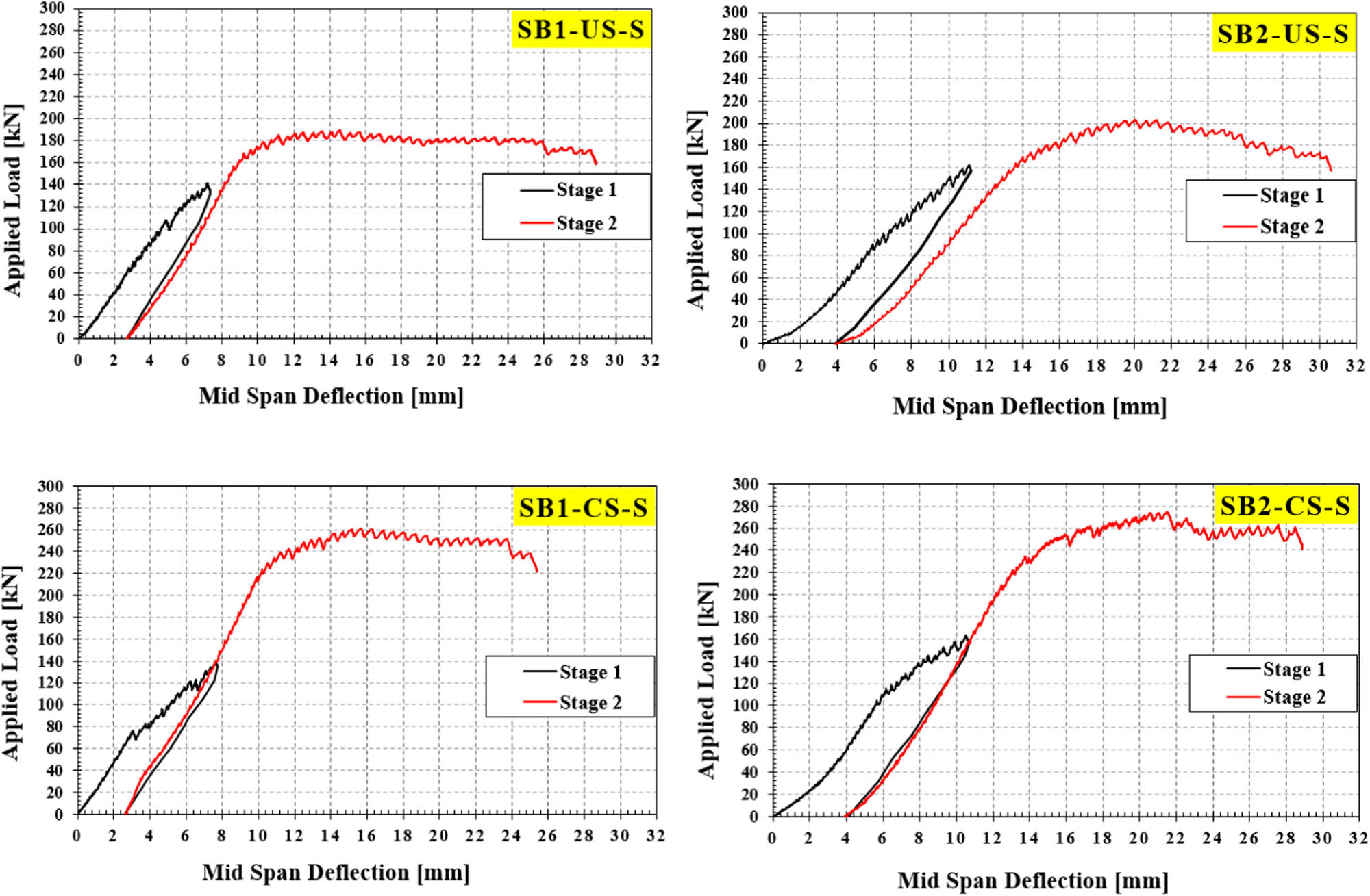
Load–vertical deflection curve at mid-span section for tested spandrel beams.
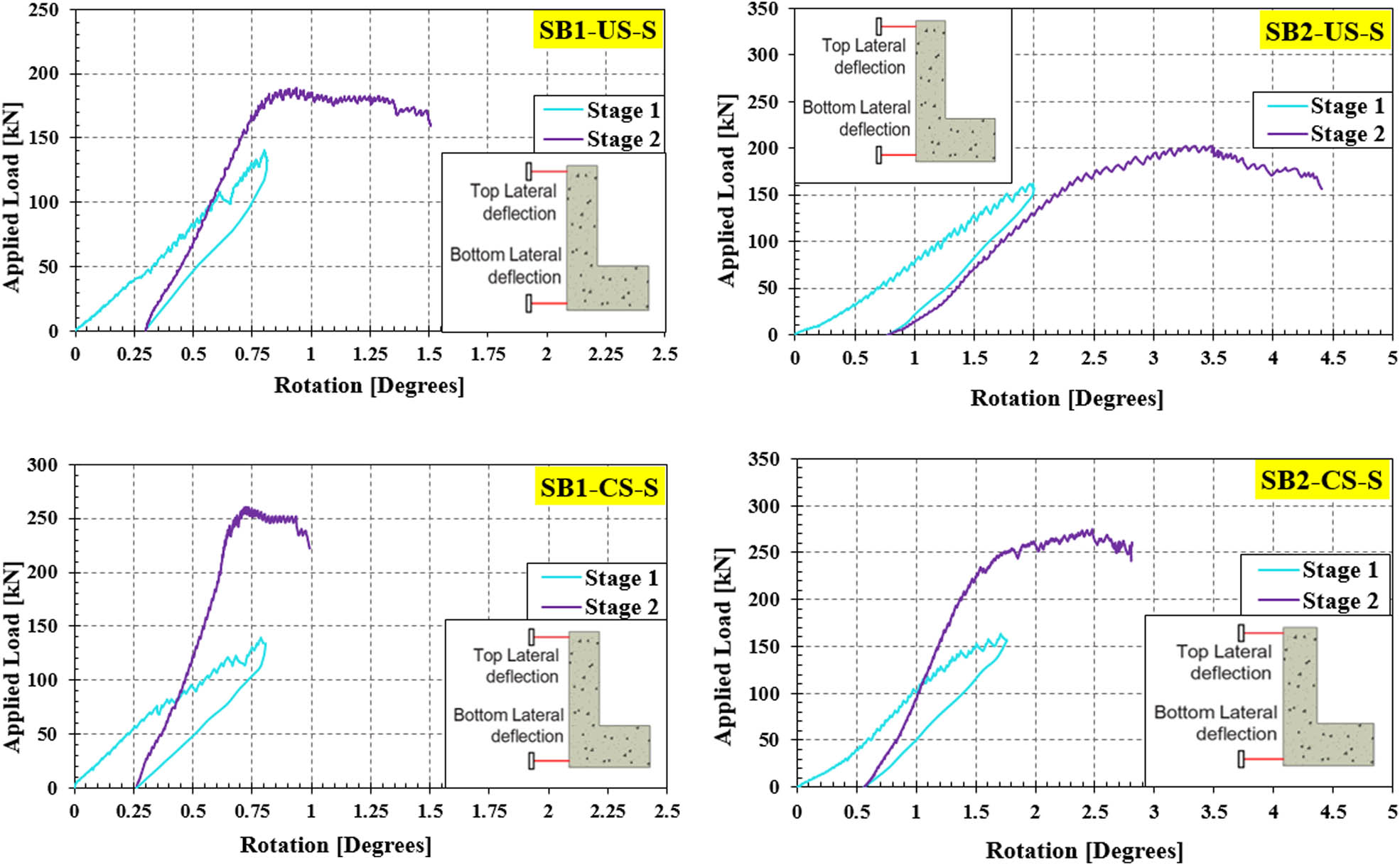
Load–rotation curves at mid-span section for tested spandrel beams.
3.4 Strain of different reinforcing steel and CFRP strips
Different strain gauges were glued on longitudinal and transverse steel reinforcement and CFRP sheets to monitor the strain evolution during loading for each specimen. Among the 14 electrical resistance strain gauges which were used, four of them in this section were selected to demonstrate the load–strain response, mainly SG-2 (on the vertical leg of the transverse reinforcement of the web), SG-4 (on the web’s skin longitudinal bar), SG-7 (on the main longitudinal bar of the ledge), and SG-14 (on CFRP strip), see Figure 8.
The load–strain relationships are illustrated in Figure 12. As mentioned above, the tested spandrel beams were first exposed to incremental concentrated load up to the load that achieved a strain in the web’s vertical steel stirrup at the mid-span section of
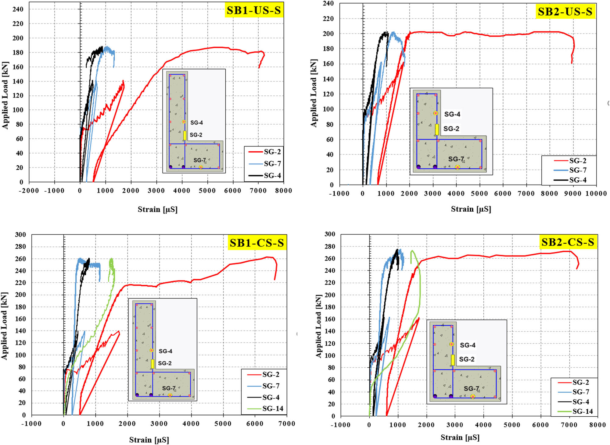
Load–strain curves in steel reinforcement and CFRP strips at different loading stages.
The spandrel beams were unloaded in one step. On the other hand, at the unloading stage, the strain (SG-2) is gradually decreased where the residual value ranged between 503 and 630
Finally, at the second stage (i.e., the reloading stage) the strain in SG-2 was progressively increased in all specimens and exceeded the yielding strain of
It is interesting to note that the strain value in CFRP strips (SG-14) attained
4 Conclusions
This article investigated the performance of a realistic strengthening that includes flexure, shear, and torsion capacities of spandrel beams under a one-point eccentric static load. The article focuses on monitoring the failure mode and recording the torsional capacity. Depending on the outcomes of this study, the following conclusions were drawn:
The behavior of all spandrel beams was similar at the load level corresponding to a stress level in the web’s transverse steel bars of 0.6
Diagonal shear cracks on the end regions of the web’s frontal face were initiated from the outer corners of the ledge and extended up with an initial angle of approximately 45°. The increasing eccentric vertical load caused the inclined cracks to change their orientation and became flattened out toward mid-span, which reflected the shear and torsion effect.
The propagation of critical diagonal cracks and the cracks skewed across the top surface of the web depends on the implementation of the strengthening scheme. The benefits provided by CFRP strips include minimizing the propagation of critical diagonal cracks and the cracks skewed across the top web surface. The strengthened L-spandrels SB1-CS-S and SB2-CS-S had little skewed cracks across the top surface of the web in comparison to the unstrengthened L-spandrels SB1-US-S and SB2-US-S.
The strengthened L-spandrels had control of crack widths with minimal spalling or crushing of concrete, which was attributed to the confinement effect provided by CFRP continuous strips. During the tests, debonding or rupture of CFRP was not apparent.
Eccentric vertical loads concentrated on spandrel ledge induced torsional distress and reduce a spandrel load-bearing capacity. Using CFRP strip wrapping is efficient in providing additional torsional capacity. In this experimental study, the torsional strength of the spandrel SB1-CS-S exceeded that of the traditional spandrel SB1-US-S by up to 37%, while the increase in SB2-CS-S was about 38% when compared to its counterpart spandrel SB2-US-S. These results confirmed that the performance of strengthening spandrels was satisfactory and will increase the torsional strength of reinforced concrete spandrel beams. Strengthening spandrels could avoid torsion brittle failure.
All four L-spandrels showed the same failure mode including moderate diagonal cracking on the web’s inner face and moderate flexural cracking on the web’s outer face at the stage 1 of loading. At the stage 2 of loading, the spandrel s failure modes began to differ depending on the availability of the CFRP strips. The failure mode of the spandrel beams was combined shear and torsion along a skewed diagonal plane.
The results indicate that using CFRP strips show improvement in restricting the deflections and rotation of spandrel beams. The reduction in rotation degree of the spandrel SB1-CS-S when compared to the unstrengthened spandrel SB1-US-S was 33%, while the reduction in SB2-CS-S was about 36% when compared to its counterpart spandrel beam SB2-US-S, which indicates an increase in spandrels stiffness.
Acknowledgments
The authors are very grateful to the Civil Engineering Department at the University of Baghdad for providing the lab equipment for testing.
-
Funding information: The authors state no funding involved.
-
Author contributions: All authors have accepted responsibility for the entire content of this manuscript and approved its submission.
-
Conflict of interest: The authors state no conflict of interest.
References
[1] Lucier GW, Walter C, Rizkalla SH, Zia PZ, Klein GJ. Development of a rational design methodology for precast slender spandrel beams: part 1, experimental results. PCI J. 2011a;56(2):88–112.10.15554/pcij.03012011.88.112Suche in Google Scholar
[2] ACI 318-19. Building code requirements for structural concrete and commentary. Farmington Hills (MI), USA: American Concrete Institute; 2019.Suche in Google Scholar
[3] Precast/Prestressed Concrete Institute. PCI design handbook: precast and prestressed concrete. 8th ed. Chicago (IL), USA: PCI; 2017.Suche in Google Scholar
[4] Zia PZ, McGee WD. Torsion design of prestressed concrete. PCI J. 1974;19(2):46–65.10.15554/pcij.03011974.46.65Suche in Google Scholar
[5] Zia PZ, Hsu TT. Design for torsion and shear in prestressed concrete flexural members. PCI J. 2004;49(3):34–42.10.15554/pcij.05012004.34.42Suche in Google Scholar
[6] Ali M. Strength and behaviour of reinforced concrete spandrel beams [dissertation]. Edinburgh: The University of Edinburgh; 1983.Suche in Google Scholar
[7] Raths CH. Spandrel beam behavior and design. PCI J. 1984;29(2):62–131.10.15554/pcij.03011984.62.131Suche in Google Scholar
[8] Klein GJ. Design of spandrel beams. PCI J. 1986;31(5):76–124.10.15554/pcij.09011986.76.124Suche in Google Scholar
[9] Logan DR. L-spandrels: can torsional distress be induced by eccentric vertical loading? PCI J. 2007;52(2):46–61.10.15554/pcij.03012007.46.61Suche in Google Scholar
[10] Salom PR, Gergely J, Young DT. Torsional strengthening of spandrel beams with CFRP laminates. J Compos Constr. 2004;8(2):157–62.10.1061/(ASCE)1090-0268(2004)8:2(157)Suche in Google Scholar
[11] Hassan TK, Lucier GW, Rizkalla SH, Zia PZ. Modeling of L-shaped, precast, prestressed concrete spandrels. PCI J. 2007;52(2):78–92.10.15554/pcij.03012007.78.92Suche in Google Scholar
[12] Walter CA. Behavior of slender, precast L-shaped spandrel beams [dissertation]. Raleigh: North Carolina State University; 2008.Suche in Google Scholar
[13] Lucier GW, Walter C, Rizkalla SH, Zia PZ, Klein GJ. Development of a rational design methodology for precast slender spandrel beams: Part 2, analysis and design guidelines. PCI J. 2011b;56(4):106–33.10.15554/pcij.09012011.106.133Suche in Google Scholar
[14] Nafadi MK, Lucier GW, Rizkalla SH, Zia PZ, Klein GJ. Ledge behavior and strength of long-span L-shaped beams. PCI J. 2018;63(2):50–66.10.15554/pcij63.2-01Suche in Google Scholar
[15] Hariharan V, Lucier GW, Rizkalla SH, Zia PZ, Klein GJ, Gleich H. Behavior of compact L-shaped spandrel beams with alternative web reinforcement. PCI J. 2019;64(2):39–54.10.15554/pcij64.2-04Suche in Google Scholar
[16] Abbas RM, Fadala WA. Numerical investigation of the flexure behavior of reinforced concrete spandrel beams with distributed tension reinforcement. J Eng. 2022;28(3):14–31.10.31026/j.eng.2022.03.02Suche in Google Scholar
[17] ASTM C 39-05. Standard test method for compressive strength of cylindrical concrete specimens. West Conshohocken (PA), USA: ASTM International; 2005.Suche in Google Scholar
[18] ASTM A370-19. Standard test methods and definitions for mechanical testing of steel products. American society for testing and materials. West Conshohocken (PA), USA: ASTM International; 2019.Suche in Google Scholar
[19] Kamara ME, Novak LC, editors. PCA Notes on ACI 318-11. Building code requirements for structural concrete with design applications. Skokie (IL), USA: Portland Cement Association; 2013.Suche in Google Scholar
[20] ACI 440.2R-08. Guide for the design and construction of externally bonded FRP systems for strengthening concrete structures. Farmington Hills (MI), USA: American Concrete Institute; 2008.Suche in Google Scholar
© 2023 the author(s), published by De Gruyter
This work is licensed under the Creative Commons Attribution 4.0 International License.
Artikel in diesem Heft
- Research Articles
- The mechanical properties of lightweight (volcanic pumice) concrete containing fibers with exposure to high temperatures
- Experimental investigation on the influence of partially stabilised nano-ZrO2 on the properties of prepared clay-based refractory mortar
- Investigation of cycloaliphatic amine-cured bisphenol-A epoxy resin under quenching treatment and the effect on its carbon fiber composite lamination strength
- Influence on compressive and tensile strength properties of fiber-reinforced concrete using polypropylene, jute, and coir fiber
- Estimation of uniaxial compressive and indirect tensile strengths of intact rock from Schmidt hammer rebound number
- Effect of calcined diatomaceous earth, polypropylene fiber, and glass fiber on the mechanical properties of ultra-high-performance fiber-reinforced concrete
- Analysis of the tensile and bending strengths of the joints of “Gigantochloa apus” bamboo composite laminated boards with epoxy resin matrix
- Performance analysis of subgrade in asphaltic rail track design and Indonesia’s existing ballasted track
- Utilization of hybrid fibers in different types of concrete and their activity
- Validated three-dimensional finite element modeling for static behavior of RC tapered columns
- Mechanical properties and durability of ultra-high-performance concrete with calcined diatomaceous earth as cement replacement
- Characterization of rutting resistance of warm-modified asphalt mixtures tested in a dynamic shear rheometer
- Microstructural characteristics and mechanical properties of rotary friction-welded dissimilar AISI 431 steel/AISI 1018 steel joints
- Wear performance analysis of B4C and graphene particles reinforced Al–Cu alloy based composites using Taguchi method
- Connective and magnetic effects in a curved wavy channel with nanoparticles under different waveforms
- Development of AHP-embedded Deng’s hybrid MCDM model in micro-EDM using carbon-coated electrode
- Characterization of wear and fatigue behavior of aluminum piston alloy using alumina nanoparticles
- Evaluation of mechanical properties of fiber-reinforced syntactic foam thermoset composites: A robust artificial intelligence modeling approach for improved accuracy with little datasets
- Assessment of the beam configuration effects on designed beam–column connection structures using FE methodology based on experimental benchmarking
- Influence of graphene coating in electrical discharge machining with an aluminum electrode
- A novel fiberglass-reinforced polyurethane elastomer as the core sandwich material of the ship–plate system
- Seismic monitoring of strength in stabilized foundations by P-wave reflection and downhole geophysical logging for drill borehole core
- Blood flow analysis in narrow channel with activation energy and nonlinear thermal radiation
- Investigation of machining characterization of solar material on WEDM process through response surface methodology
- High-temperature oxidation and hot corrosion behavior of the Inconel 738LC coating with and without Al2O3-CNTs
- Influence of flexoelectric effect on the bending rigidity of a Timoshenko graphene-reinforced nanorod
- An analysis of longitudinal residual stresses in EN AW-5083 alloy strips as a function of cold-rolling process parameters
- Assessment of the OTEC cold water pipe design under bending loading: A benchmarking and parametric study using finite element approach
- A theoretical study of mechanical source in a hygrothermoelastic medium with an overlying non-viscous fluid
- An atomistic study on the strain rate and temperature dependences of the plastic deformation Cu–Au core–shell nanowires: On the role of dislocations
- Effect of lightweight expanded clay aggregate as partial replacement of coarse aggregate on the mechanical properties of fire-exposed concrete
- Utilization of nanoparticles and waste materials in cement mortars
- Investigation of the ability of steel plate shear walls against designed cyclic loadings: Benchmarking and parametric study
- Effect of truck and train loading on permanent deformation and fatigue cracking behavior of asphalt concrete in flexible pavement highway and asphaltic overlayment track
- The impact of zirconia nanoparticles on the mechanical characteristics of 7075 aluminum alloy
- Investigation of the performance of integrated intelligent models to predict the roughness of Ti6Al4V end-milled surface with uncoated cutting tool
- Low-temperature relaxation of various samarium phosphate glasses
- Disposal of demolished waste as partial fine aggregate replacement in roller-compacted concrete
- Review Articles
- Assessment of eggshell-based material as a green-composite filler: Project milestones and future potential as an engineering material
- Effect of post-processing treatments on mechanical performance of cold spray coating – an overview
- Internal curing of ultra-high-performance concrete: A comprehensive overview
- Special Issue: Sustainability and Development in Civil Engineering - Part II
- Behavior of circular skirted footing on gypseous soil subjected to water infiltration
- Numerical analysis of slopes treated by nano-materials
- Soil–water characteristic curve of unsaturated collapsible soils
- A new sand raining technique to reconstitute large sand specimens
- Groundwater flow modeling and hydraulic assessment of Al-Ruhbah region, Iraq
- Proposing an inflatable rubber dam on the Tidal Shatt Al-Arab River, Southern Iraq
- Sustainable high-strength lightweight concrete with pumice stone and sugar molasses
- Transient response and performance of prestressed concrete deep T-beams with large web openings under impact loading
- Shear transfer strength estimation of concrete elements using generalized artificial neural network models
- Simulation and assessment of water supply network for specified districts at Najaf Governorate
- Comparison between cement and chemically improved sandy soil by column models using low-pressure injection laboratory setup
- Alteration of physicochemical properties of tap water passing through different intensities of magnetic field
- Numerical analysis of reinforced concrete beams subjected to impact loads
- The peristaltic flow for Carreau fluid through an elastic channel
- Efficiency of CFRP torsional strengthening technique for L-shaped spandrel reinforced concrete beams
- Numerical modeling of connected piled raft foundation under seismic loading in layered soils
- Predicting the performance of retaining structure under seismic loads by PLAXIS software
- Effect of surcharge load location on the behavior of cantilever retaining wall
- Shear strength behavior of organic soils treated with fly ash and fly ash-based geopolymer
- Dynamic response of a two-story steel structure subjected to earthquake excitation by using deterministic and nondeterministic approaches
- Nonlinear-finite-element analysis of reactive powder concrete columns subjected to eccentric compressive load
- An experimental study of the effect of lateral static load on cyclic response of pile group in sandy soil