Electrochemical Discharge Grinding of Metal Matrix Composites Using Shaped Abrasive Tools Formed by Sintered Bronze/diamond
-
Jiangwen Liu
 und
Xiaolei Chen
und
Xiaolei Chen

Abstract
Electrochemical discharge machining (ECDM) is a well-known process for machining of particulate reinforced metal matrix composites (MMCs). However, ECDM process suffers several drawbacks such as the lower material removal rate (MRR), high risks of tool wear rate (TWR) and relatively poor surface quality, etc. This study proposes a kind of electrochemical discharge grinding machining (ECDGM) method which employs a special shaped tool electrode. During the process, not only the can the hybrid action of electrochemical dissolution, spark erosion, and abrasive grinding improve the performance of machining MMCs, but also the special shaped of the tool electrode can be used to discharge the machined debris. And thus a higher machining efficiency and lower TWR can be obtained. The performance of developed process was conducted on machining of SiC particulate reinforced aluminum workpiece. The role of peak curre+nt, pulse duration, duty cycle, rotary speed and abrasive grit size has been investigated on MMR and TWR using the nonabrasive round electrode, abrasive round electrode, and abrasive shaped electrode respectively. The experimental results showed that using the shaped abrasive electrode for machining MMCs can achieve a higher MRR and lower TWR, as compared to the non-abrasive round electrode, abrasive round electrode. Besides, the orthogonal method was employed to analyze the relative importance of the machining parameters on MRR and TWR, it has been observed that MRR is affected by the processing parameters following the order of rotary speed > peak current > duty cycle > pulse duration, and TWR is following the order of peak current > duty cycle > pulse duration > rotary speed.
1 Introduction
The metal matrix composites (MMCs) are composite material with two or more phases. This study mainly focuses on an important type of MMC materials, SiC particle reinforced Al-alloy composites [1]. This SiC particle reinforced aluminum-silicon carbide (Al/SiC) metal matrix composites (MMCs) have superior performance in such a way that is unmatched by most other existing materials, such as high specific strength, high specific stiffness, excellent wear resistance, heat resistance [2, 3, 4], toughness, corrosion resistance [5], low thermal expansion coefficient [6], etc., which have broad application prospects in aerospace, automotive, electronics and other fields [4, 5, 7].
Although MMCs have excellent physical and chemical properties, at the same time, it is also a typical high hardness, high strength, difficult-to-machine material, moreover, the processing becomes more difficult as the volume fraction and the size of silicon carbide increases. In particular, the applications o fMMCs in industries are limited due to the difficulty of secondary processing. Over the years, the secondary processing of MMCs has been extensively studied by researchers. However, the research results show that the existing processing methods are difficult to meet the requirements of metal matrix composites when taking high efficiency, high surface quality, and high precision machining into consideration.
With the traditional mechanical machining methods, the problematic machining characteristics are mainly reflected in the high risk of tool wear [8], high cost, and low surface quality [9]. Due to the drawbacks of the traditional processing methods mentioned above, many experts and scholars have begun to turn their attention to the field of unconventional machining processes, using unconventional machining methods to process metal matrix composites materials, for instance, using abrasive water jet processing [10], laser beam processing [11], electrochemical processing [12], Electrical discharge machining [13] and other special processing methods [14]. However, there is no risk of tool wear; they have been found unsuitable for processing these materials effectively at low cost due to their own limitations. Because of the particularity of aluminum-silicon carbide metal matrix composites, they still have not overcome such a problem that the surface quality is so poor. The processing accuracy is not high, and it is challenging to meet the needs of industrial applications.
Generally, as for MMCs, although the efficiency of EDM is relatively low, EDM and WEDM have higher processing precision, what’s more, it can be used to process complex geometries [15, 16]. At the same time, researchers have conducted many experimental investigations and optimizations on EDM of MMCs [17, 18]. Even though there are still many problems coming into existence, it is difficult to remove the form of vaporization or melting during the processing due to the high melting point of the silicon carbide. As the processing moves on, the high-melting silicon carbide will continue to accumulate on the machined surface, causing abnormal arc discharge and electrode tool wear. It is also difficult to meet the actual needs due to the poor surface quality of the machined workpiece [4, 7].
As for ECM, machining efficiency and surface finishing are two critical problems that need to be resolved [19], while electrochemical discharge machining (ECDM) is an efficient processing method [20]. In the process of ECDM machining of MMCs, it can not only obtain a higher MRR compared to EDM [21], but also the electrochemical effect in the process can promote the detachment of the silicon carbide phase and prevent it from accumulating on the machined surface. Hence, it can effectively reduce the occurrence of abnormal arc discharge phenomenon. However, due to the electrical spark discharge effect, the wear of the tool electrode during the process is still hard to avoid. Furthermore, its machining precision accuracy and surface quality have not been substantially improved compared to EDM [22].
In machining of MMCs, although there is very little research on this aspect, the grinding effect of abrasive grits has been proven to obtain a non-damaged machined surface and high dimensional accuracy [23, 24]. To further improve the surface quality and processing efficiency, the authors proposed the grinding-aided electrochemical discharge machining (ECDGM) to machine MMCs using an abrasive round electrode. The hybrid method combining the whole advantages of the grinding and ECDM technologies, it was found that the grinding process can effectively remove the recast material, and the processing efficiency and the surface quality were higher than that of the ECDM [25]. However, although good surface quality can be obtained by grinding, the processing efficiency is relatively low.
This study proposes a method toward synchronous electrochemical discharge grinding machining (ECDGM) with a hybrid action of electrochemical dissolution, spark erosion, and abrasive grinding in the machining of MMCs employs a special shaped abrasive tool electrode. The purpose of combining the different machining process is to obtain the better performance compared to separate machining processes by exploiting the advantages and avoiding the disadvantages of EDM, ECM, and grinding process in the machining of MMCs. This paper mainly studied the MRR and TWR, the MRR mechanism and the surface quality of the machined workpiece will be studied in another paper.
2 Materials and methods
This work developed a hybrid process that combines EDM, ECM, and grinding action synchronously on a unique electrode tool, aiming to improve the material removal rate and reduce TWR. The experiments conducted on aluminum-silicon carbide MMCs, whose reinforced SiC have an average particle size of 20 with 20vol%, the micrograph of the composite as shown in Figure 1. The electrolyte applied for the experimental study is 0.75wt% NaNO3 solution.
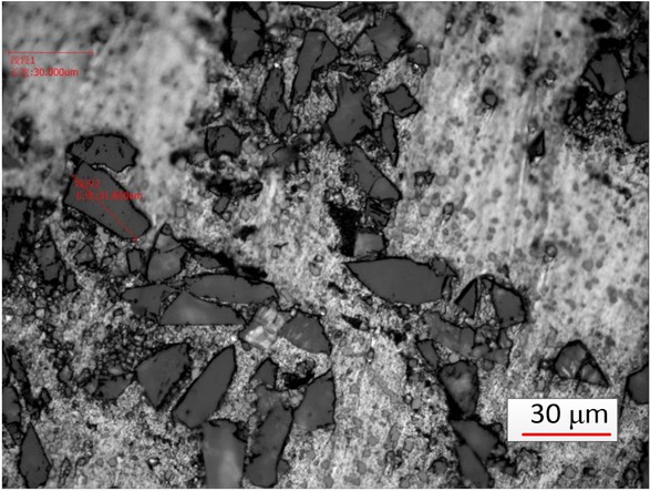
SEM micrograph of the composite.
The principle of the ECDGM is shown in Figure 2 and Figure 3. In the process of the ECDGM, the material removal phenomenon can be divided into three phases: electrochemical dissolution, spark erosion, and abrasive grinding, which is shown in Figure 3(b) in detail. The electrode tool consists of a conductive metal substrate and an insulated diamond formed by sintering, the diamond is partially exposed and serves as grinding abrasive. In the first phase, the role of ECM action is not just to remove materials, what most importantly is, more hydrogen bubbles come into being, which is more conducive to the formation of electrical spark breakdown conditions, besides, it can increase the spark discharge gap of the EDM, which make the debris easier to discharge. When it comes to the second phase, the electro-spark erosion occurs, the conductive metal substrate serves as an electrode performing discharges to remove workpiece materials and simultaneously forming the hot recast layer. In the third phase, abrasive grinding begins to work, and the exposed diamond makes contact with the recast layer and softened workpiece during the abrasive grinding process. The three processes are carried out simultaneously. Due to this, a much higher MRR has been obtained, now, to improve debris evacuation efficiency, a shaped abrasive tool has been designed, increasing the debris removal gap by adding a flute on the electrode tool is shown in Figure 3(a).
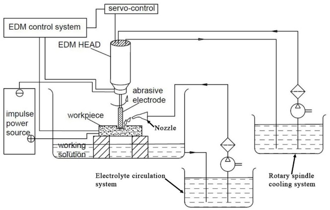
The principle of synchronous hybrid ECDGM with shaped abrasive electrode.
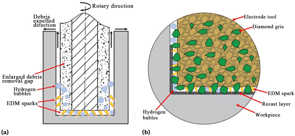
Schematic diagram of synchronous hybrid ECDGM: (a) debris discharge using shaped abrasive electrode; (b) partial enlargement diagram of the ECDGM.
Self-assembled experimental equipment is employed for experimental study, which is shown in Figure 4, which consists of a spindle, servo control system, frequency converter, and a high-frequency pulse power supply. A rotary spindle with a max 24000 rpm is fixed to the Z-axis, where the electrode is held. In machining, the current flows through the electric transmission system placed in insulated polyoxymethylene (POM), which is supplied by the high-frequency pulse power supply. A servo control system maintains the gap between the tool electrode and workpiece. It is using external flushing to experiment. To improve debris evacuation efficiency, a shaped abrasive tool has been designed. For the ECDM discharge gap is about tens of micros, this tool electrode has a volume fraction of 45%of diamond grits of nominal size 120 μm,which exposing height is about tens of micros. The schematic diagram of the shape abrasive electrode’s preparation is shown in Figure 5 (a), which can be divided into three steps. In the first step, it is sintered at 700∘C, an abrasive round electrode has been obtained, which was provided by Hangzhou Huhao Technology Co., Ltd. The second step uses a mold copper electrode with a structure complementary to the target electrode as the anode and the abrasive round electrode as the cathode, and then, the mold copper electrode feeds toward the abrasive round electrode while performing spark discharge. In the last step, finally, after the feed is completed, an efficient shaped abrasive electrode has been obtained. Figure 5(b) shows the actual photo of the abrasive electrode. What’s more, in order to clearly observe the abrasive electrode’s surface morphology, SEM photographs of the abrasive electrode have been obtained, which is shown in Figure 6.
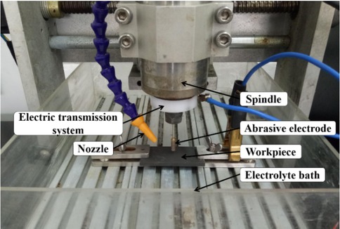
The actual experimental setup.
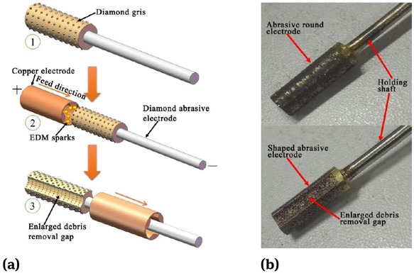
(a) Schematic diagram of preparation of shaped abrasive electrode; (b) Actual photo of the abrasive electrode.
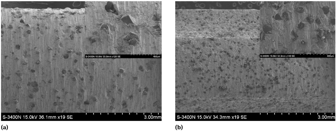
SEM photographs of the abrasive electrode: (a) Abrasive round electrode; (b) Abrasive shaped electrode.
The role of peak current, pulse duration, duty cycle, rotary speed, and abrasive grit size has been investigated on material removal rate (MMR) and tool wear rate (TWR) using the non-abrasive round electrode, abrasive round electrode, and abrasive shaped electrode respectively. The MRR is obtained by dividing the mass difference of the removed workpiece by the machining time, which is given by:
Where M1 is the mass of workpiece before machining, M2 is the mass of workpiece after machining, t is the machining time.
Vtool is tool electrode wear rate and the Vtool is obtained by dividing the mass difference of the before and after tool electrode by the machining time, which is given by:
Where m1 is the mass of tool electrode before machining, m2 is the mass of tool electrode after machining, t is the machining time.
The TWR is given by:
To study the influence of the input parameters on MRR and TWR, the role of peak current, pulse duration, duty cycle, rotary speed and abrasive grit size has been investigated by using the non-abrasive round electrode, abrasive round electrode, and shaped abrasive electrode respectively. Each experiment was repeatedly carried out three times in random order, whose average value was used to analyze. The range of input parameters was determined after the pilot experiment. Table 1 shows the machining and input parameters condition. An electronic micro-weighing balance has been employed to measuring the weight of workpiece and tool electrode, before measuring it, an ultrasonic vibration cleaning machine was used to clean each specimen for 180 s.
The machining and input parameters condition.
| Machining conditions | Values |
|---|---|
| Workpiece | Aluminum-silicon carbide |
| Polarity | Electrode (negative); Workpiece (positive) |
| Electrolyte | 0.75 wt% NaNO3 |
| Machining time (min) | 3 |
| Applied voltage (V) | 120 |
| Peak current (A) | 15, 20, 25, 30, 35 |
| Pulse duration (μs) | 24, 48, 72, 96, 120 |
| Duty cycle | 1:3,1:4, 1:5, 1:6, 1:7, 1:8 |
| Rotary speed (rpm) | 600, 1200, 1800, 2400, 3000 |
| Abrasive grit size (M) | 100, 170, 320 |
3 Results and discussion
3.1 Influence of abrasive grit size on MRR and TWR
In the ECDGM process, to find out which sizes of abrasive grits can achieve higher MRR, experiments of different size of abrasive grits (M100, M170, M320) have been investigated, the smaller the value, the larger the size of the abrasive grits.
Figure 7 shows the influence of abrasive grits size on MRR and TWR for three different sizes of abrasive grits during ECDGM of MMCs respectively, while the input parameters such as applied voltage = 120 V, pulse duration = 120 μs, duty cycle = 1:5 , rotary speed = 2400 rpm. It has been clearly observed (Figure 7 (a)) that the MRR sharply increase with increase in current from15A to 20A, and then the rate of rise in MRR begins to slow down with an increase in current from 20A to 35A. What’s more, the grits of M100 has much higher MRR than the other two under the same experimental conditions. Furthermore, according to the result of Figure 7(b), the grits of M100 have much lower TWR than the other two with increasing of the current. When the abrasive grits are larger, the distance between the workpiece and metal phase of the electrode (i.e. the machining gap) will be large accordingly.Whenthe machining gap is larger than the discharge gap, it is difficult to form a stable EDM process. Therefore, by using large-size abrasive electrodes, the grinding effect is dominant, and the impact of Electrical discharge machining gets weakened. Besides, the composite material contains SiC particles as a component, which is a typical difficult-to-process material. Therefore, the processing efficiency of the M170 and M320 grits is lower than M100, and the grits of M100 have much lower TWR than M170 and M320. Hence, the grits of M100 is selected to use to carry out the following experiments.
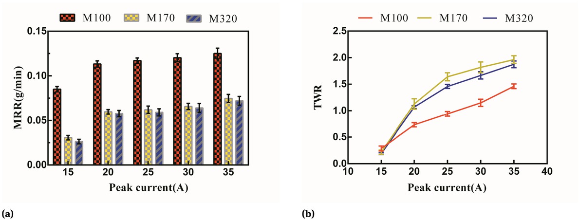
Influence of abrasive grits size on MRR and TWR (applied voltage = 120 V, pulse duration = 120 μs, duty cycle = 1:5, rotary speed = 2400 rpm).
3.2 Influence of peak current on MRR and TWR
Figure 8 shows the influence of peak current on MRR and TWR for three different tool electrodes during machining of MMCs, respectively, while the input parameters such as applied voltage = 120 V pulse duration , duty cycle = 1:5, rotary speed = 2400 rpm. It has been found out in Figure 8(a) that the MRR of the abrasive shaped electrode was higher (about three times) than that of the non-abrasive round electrode, and the MRR of the abrasive round electrode was also higher (about 2.4 times) than that of the non-abrasive round electrode. As for non-abrasive round electrode in ECDM of MMCs, the MRR increases very slowly with increase in peak current from 15A to 35A, that’s because not only the EDM action enhanced but also the ECM action enhanced with the increase of peak current, leading to more material removal per unit of time, however, the debris evacuation becomes difficult due to the limited machining gap, that’s why the MRR increases with increase in peak current from 15A to 25A, and the MRR even decreases with increase in peak current from 25A to 35A. The abrasive round electrode has shown a similar tendency in ECDM of MMCs, namely as ECDGM. Compared to the nonabrasive round electrode during ECDM of MMCs, the workpiece is removed by the ECDM and grinding action separately with the abrasive round electrode; hence, a higher MRR can be obtained. Unfortunately, when peak current increases (more than 20A), a greater energy heat is generated resulting in removing a larger volume of workpiece debris as well as the detached grinding grits of the electrode, the machining gap is so narrow that it is difficult to evacuate the debris, until the workpiece debris and the detached grinding grits are melted to smaller one and finally are evacuated out, which reduce the MRR. The abrasive-shaped electrode can discharge a larger volume of workpiece debris and detached grinding grits with increasing peak current due to the enlarged debris removal gap of tool electrode. Consequently, a much higher MRR has been obtained.
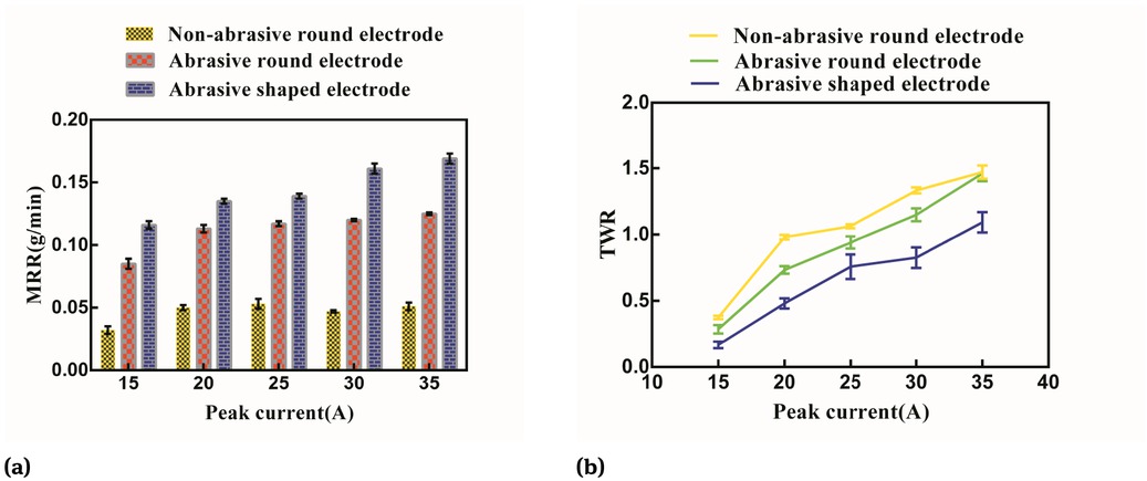
Influence of peak current on MRR and TWR (applied voltage = 120 V, pulse duration = 120 μs, duty cycle = 1:5, rotary speed = 2400 rpm).
It has been observed from Figure 8(b) that abrasive shaped electrode has much lower TWR compared to the other two, an average of 32% lower than a round electrode, and an average of 27% lower than that of the abrasive round electrode. This can account for debris evacuation. When the abrasive-shaped electrode is used, the debris efficiently exhausts the machining gap, and the discharge process is relatively stable. When the debris is difficult to remove and accumulates in the machining gap, it is easy to form abnormal discharge conditions, so the electrode wear is significant. According to the experimental results above, we can conclude that a much higher MRR and a much lower TWR can be obtained with the abrasive shaped electrode.
3.3 Influence of pulse duration on MRR and TWR
Figure 9 shows the influence of pulse duration on MRR and TWR for three different tool electrodes during machining of MMCs, respectively, while the input parameters such as applied voltage = 120 V, peak current = 25 A, duty cycle = 1:5, rotary speed = 2400 rpm. It can be observed from Figure 8 that the three different electrodes have the similar tendency in MRR and TWR during machining of MMCs with increasing of the pulse duration, the MRR and TWR for three different electrode increases as the pulse duration increase, that’s because a rise in pulse duration means more extended time for effective discharge resulting in more materials to be removed. And the non-abrasive round electrode has the lowest MRR and the highest TWR among them. Figure 9 shows us that the abrasive shaped electrode has the highest MRR, whose average removal rate is about three times higher than that of the non-abrasive round electrode, and the lowest TWR among them (about an average of 29% lower than that of the non-abrasive round electrode), and the MRR and TWR of the abrasive round electrode just between the other two. Besides, it can be seen from Figure 9(a) that the MRR for abrasive round electrode is higher than that of the abrasive shaped electrode at a relatively lower pulse duration (less than 48 μs). On the contrary (more than 48 μs), on the one hand, that’s because small volume of materials has been removed at lower pulse duration The effective machining area for abrasive round electrode is more significant than that of abrasive shaped electrode resulting in its MRR increase, on the other hand, a relatively larger volume of materials has been removed at higher pulse duration (more than 48 μs), and the debris evacuation become difficult due to the limited machining gap of abrasive round electrode resulting in its MRR decrease. So we can conclude that it is suitable to use abrasive round electrode for machining at lower pulse duration and use abrasive shaped electrode for machining at higher pulse duration (more than 48 μs).
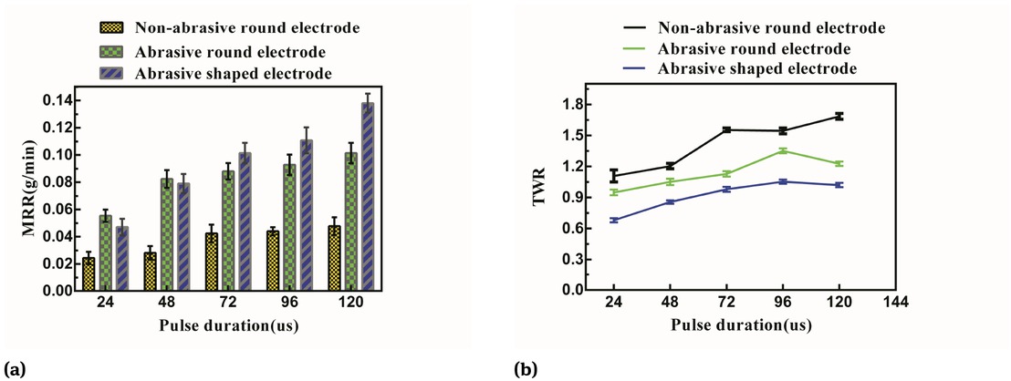
Influence of pulse duration on MRR and TWR (applied voltage = 120 V, peak current = 25 A, duty cycle = 1:5, rotary speed = 2400 rpm).
3.4 Influence of duty cycle on MRR and TWR
Figure 10 shows the influence of duty cycle on MRR and TWR for three different tool electrodes during machining of MMCs, respectively, while the input parameters such as applied voltage = 120V, peak current = 25 A, pulse duration = 120 μs, rotary speed = 2400 rpm. It has been observed from Figure 10 that the duty cycle has no apparent influence on MRR and has a significant impact on TWR for non-abrasive round electrode, and the two abrasive electrodes have a similar tendency in MRR and TWR during machining of MMCs with decreasing of the duty cycle. Furthermore, the MRR and TWR for abrasive round electrode and the abrasive shaped electrode are decreasing as the duty cycle reduces, for the reason that the smaller duty cycle means less EDM energy and ECM action during single pulse period resulting in less volume of materials to be removed. Consequently, MRR and TWR decrease.
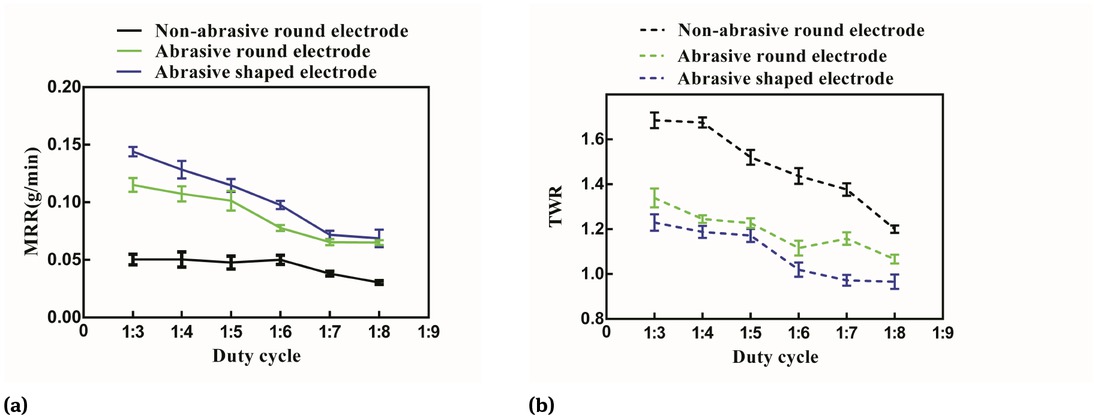
Influence of duty cycle on MRR and TWR (applied voltage = 120V, peak current = 25 A, pulse duration = 120 μs, rotary speed = 2400 rpm).
3.5 Influence of rotary speed on MRR and TWR
Figure 11 shows the influence of rotary speed on MRR and TWR for different tool electrodes during machining of MMCs, respectively, while the input parameters such as applied voltage = 120V, peak current = 25 A, pulse duration = 120 μs, duty cycle = 1:5 and the rotary speed varied from 600 r/min to 3000r/min. It can be observed from Figure 11 that the rotary speed for the non-abrasive round electrode on MRR is not significant, but having a substantial effect on its TWR, the MRR for the non-abrasive round electrode is increasing slowly as the rotary speed increase. Owing to the rotation speed increases, the debris between the electrodes is more likely to exhaust the machining gap. Therefore, the machining efficiency increases with the increasing of the rotation speed. Besides, greater grinding action can be obtained under a higher rotation speed condition. Therefore, the machining efficiency of the abrasive electrode is higher than that of the non-abrasive round electrode. Figure 11 shows us that the MRR and TWR for the two abrasive electrodes have the same trend in the machining of MMCs, the MRR for the two abrasive electrodes is increasing drastically with the rotary speed increasing. The TWR for the two abrasive electrodes is increasing from 600r/min to 1200r/min. After that, the TWR for the two abrasive electrodes has a downward trend, which means the abrasive electrode is suitable for machining at higher rotary speed. Hence, a much higher MRR and lower TWR at higher rotary speed can be obtained. For the reason that the chip force increase for an abrasive electrode as the rotary speed increase, which means the materials removed by the grinding action increases.
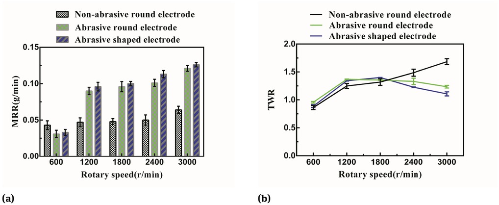
Influence of rotary speed on MRR and TWR (applied voltage = 120V, peak current= 25 A, pulse duration = 120 μs, duty cycle = 1:5).
3.6 Orthogonal experimental study on MRR and TWR
To optimize the processing parameters, and L9 (34) orthogonal analysis on MRR and TWR for abrasive shaped electrode has been investigated, the factors and levels for the orthogonal experimental study has been shown in Table 2
Factors and levels for the orthogonal experimental study.
| Levels | Factors | A (peak current) | B (pulse duration) | C (duty cycle) | D (rotary speed) |
|---|---|---|---|---|---|
| 1 | 15 | 72 | 1:3 | 1000 | |
| 2 | 25 | 96 | 1:5 | 2000 | |
| 3 | 35 | 120 | 1:7 | 3000 |
Table 3 shows the results of the orthogonal analysis on MRR for the abrasive shaped electrode of ECDGM, according to the analysis results, the relative importance of the machining parameters on MRR follow the order as: rotary speed > peak current > duty cycle > pulse duration, which means that to obtain a higher MRR, the rotary speed and peak current play an essential role in MRR for ECDGM of MMCs. While the rotary speed is 3000 r/min, the peak current is 35A, the pulse duration is 96 μs, the duty cycle is 1:3, a maximum MRR can be obtained, the results of the orthogonal analysis are in good agreement with the results of single-factor experiments.
Results of the orthogonal analysis on MRR of ECDGM.
| Series no | Factors | A (peak current) | B (pulse duration) | C (duty cycle) | D (rotary speed) | MMR (g/min) |
|---|---|---|---|---|---|---|
| 1 | 1 | 1 | 1 | 1 | 0.036 | |
| 2 | 1 | 2 | 2 | 2 | 0.059 | |
| 3 | 1 | 3 | 3 | 3 | 0.078 | |
| 4 | 2 | 1 | 2 | 3 | 0.092 | |
| 5 | 2 | 2 | 3 | 1 | 0.052 | |
| 6 | 2 | 3 | 1 | 2 | 0.111 | |
| 7 | 3 | 1 | 3 | 2 | 0.097 | |
| 8 | 3 | 2 | 1 | 3 | 0.145 | |
| 9 | 3 | 3 | 2 | 1 | 0.042 | |
| Ij | 0.173 | 0.225 | 0.292 | 0.130 | Ij = Sum | |
| (level=1) | ||||||
| II j | 0.255 | 0.256 | 0.193 | 0.267 | IIj = Sum | |
| (level=2) | ||||||
| IIIj | 0.284 | 0.231 | 0.227 | 0.315 | IIIj = Sum | |
| (level=3) | ||||||
| Ij /3 | 0.058 | 0.075 | 0.097 | 0.043 | ||
| IIj/3 | 0.085 | 0.085 | 0.064 | 0.089 | ||
| IIIj/3 | 0.095 | 0.077 | 0.076 | 0.105 | ||
| R | 0.037 | 0.010 | 0.033 | 0.062 |
Table 4 shows the results of the orthogonal analysis on TWR for the abrasive shaped electrode of ECDGM, according to the analysis results, the relative importance of the machining parameters on TWR follow the order as: peak current > duty cycle > pulse duration > rotary speed, which means that, to obtain a lower TWR, the peak current and pulse duration play a critical part in TWR for ECDGM of MMCs. While the peak current is 15A, the pulse duration is 72 μs the rotary speed is 3000 r/min, the duty cycle is 1:7, a minimum TWR can be obtained, which is in good agreement with the results of the single-factor experiments. Besides, the orthogonal analysis results on MRR and TWR of ECDGM; the higher the rotary speed, the higher the MRR and the lower the TWR.
Results of the orthogonal analysis on TWR of ECDGM.
| Series no | Factors | A (peak current) | B (pulse duration) | C (duty cycle) | D (rotary speed) | TWR |
|---|---|---|---|---|---|---|
| 1 | 1 | 1 | 1 | 1 | 0.294 | |
| 2 | 1 | 2 | 2 | 2 | 0.341 | |
| 3 | 1 | 3 | 3 | 3 | 0.162 | |
| 4 | 2 | 1 | 2 | 3 | 0.718 | |
| 5 | 2 | 2 | 3 | 1 | 0.942 | |
| 6 | 2 | 3 | 1 | 2 | 1.290 | |
| 7 | 3 | 1 | 3 | 2 | 0.949 | |
| 8 | 3 | 2 | 1 | 3 | 1.489 | |
| 9 | 3 | 3 | 2 | 1 | 1.833 | |
| Ij | 0.797 | 1.961 | 3.073 | 3.069 | Ij = Sum | |
| (level=1) | ||||||
| IIj | 2.950 | 2.772 | 2.679 | 2.580 | IIj = Sum | |
| (level=2) | ||||||
| IIIj | 4.271 | 3.283 | 2.053 | 2.369 | IIIj = Sum | |
| (level=3) | ||||||
| Ij/3 | 0.266 | 0.654 | 1.024 | 1.023 | ||
| IIj/3 | 0.983 | 0.924 | 0.893 | 0.860 | ||
| IIIj/3 | 1.424 | 1.094 | 0.684 | 0.789 | ||
| R | 1.158 | 0.440 | 0.520 | 0.234 |
3.7 SEM photographs of machined debris and surface
The SEM photographs of machined debris and are shown in Figure 12, while the input parameters such as applied voltage = 120V, peak current = 30A, pulse duration = 120 μs, duty cycle = 1:4, it has been clearly observed from Figure 12 that most of the machined debris produced by the abrasive shaped electrode (Figure 12(c)) are greater than that of the abrasive round electrode (Figure 12(b)) as well as a non-abrasive round electrode (Figure 12(a)), which indirectly proves that why the MRR for the abrasive shaped electrode in the machining of MMCs is higher than that of the other two electrodes, for the reason that the enlarged debris machining gap of the abrasive shaped electrode can discharge greater volume of workpiece debris out.
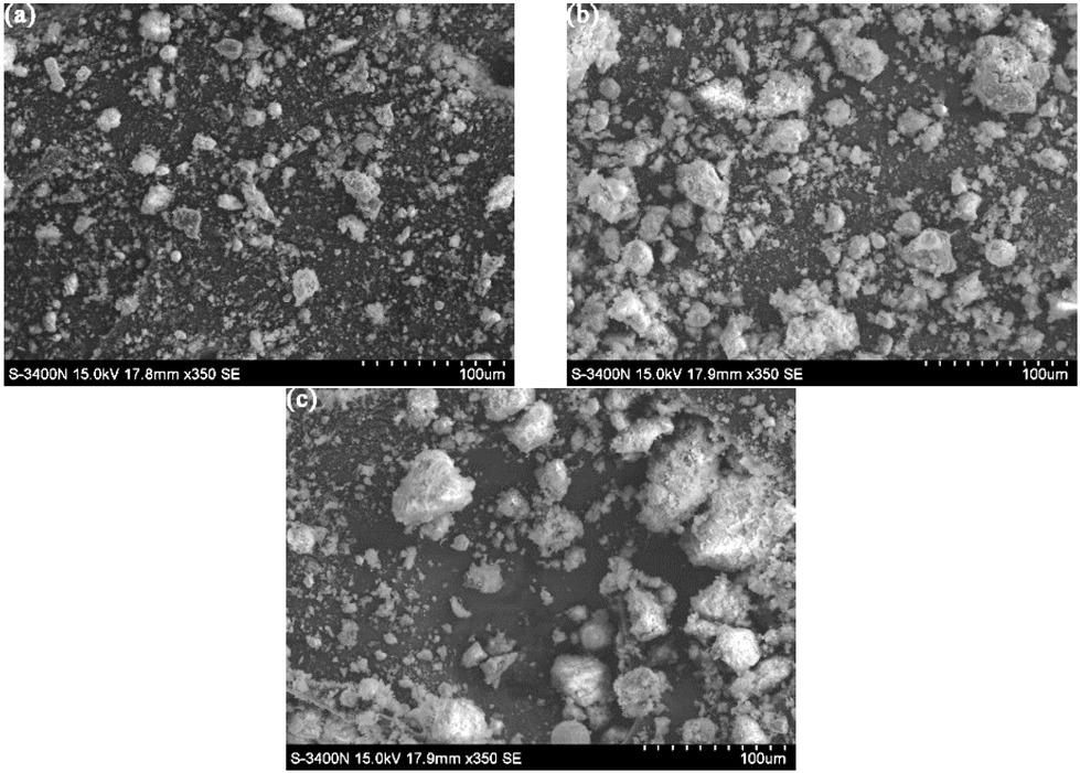
SEM photographs of machined debris: (a) Produced by non-abrasive round electrode; (b) Produced by abrasive round electrode; (c) Produced by abrasive shaped electrode.
The SEM photographs of the machined surface are shown in Figure 13, while the input parameters such as applied voltage = 120V, peak current = 15A, pulse duration = 120μs, duty cycle = 1:4. Figure 13(a) shows us that the machined surface produced by the non-abrasive round electrode, which is composed of recast layer, electrical spark crater, and crack. While the machined surface produces by the abrasive round electrode (shown in Figure 13(b, c) are some electrical spark crater there, almost no recast materials, therefore, a relatively good surface quality can be achieved by using the abrasive electrode. As can be seen from Figure 14, the surface roughness of the machined surface with the non-abrasive round electrode is large than the abrasive electrode. These can account for grinding action, the surface defects (such as recast materials and electrical spark crater) can reduce. Hence the surface finish quality can be improved via the abrasive electrode.
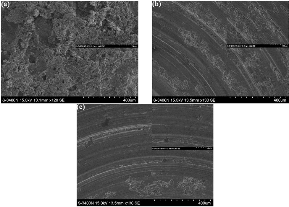
SEM photographs of machined surface: (a) Produced by non-abrasive round electrode; (b) Produced by abrasive round electrode; (c) Produced by abrasive shaped electrode.
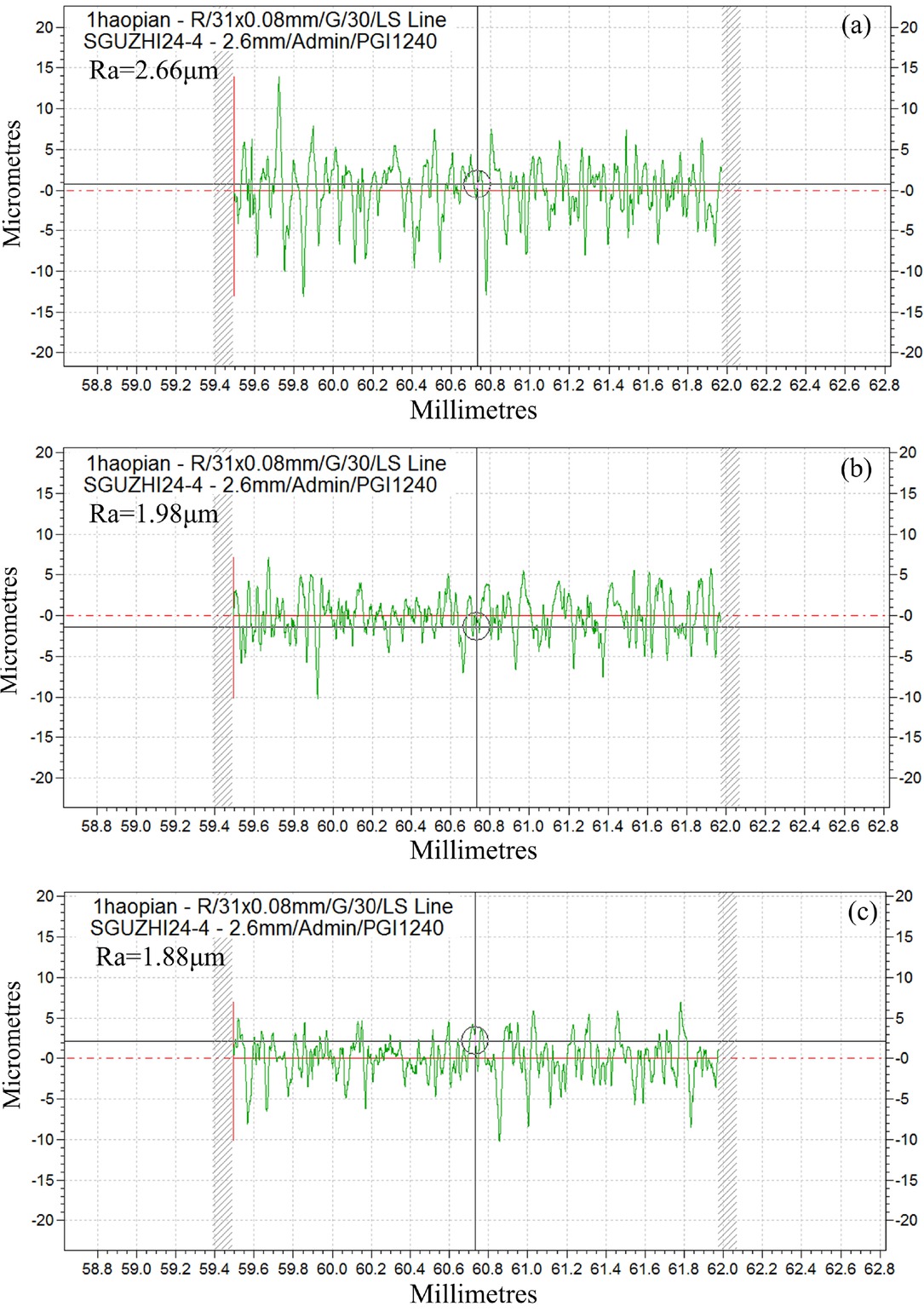
Surface roughness of machined surface: (a) Produced by non-abrasive round electrode; (b) Produced by abrasive round electrode; (c) Produced by abrasive shaped electrode.
4 Conclusions
In this research work, the performance comparison experiment among the non-abrasive round electrode, abrasive round electrode, and the abrasive shaped electrode has been experimentally investigated on MMCs taking the influence of abrasive grit size, peak current, pulse duration, duty cycle, and rotary speed on MRR and TWR into consideration. The experimental conclusions are summarized as follows:
The grits of M100 has much higher MRR and much lower TWR than the other two as the peak current increase from 15A to 35A. Hence, the grits of M100 is selected to use to carry out the comparative experiments.
A much higher MRR and much lower TWR can be obtained by using an abrasive shaped electrode with the peak current, pulse duration, and duty cycle increasing due to the enlarged debris removal gap of tool electrode, compared to the other two electrodes.
A much higher MRR and lower TWR at higher rotary speed can be obtained because the chip force increases for an abrasive electrode as the rotary speed increases, which means the grinding action increases remove the materials.
The relative importance of the machining parameters on MRR follow the order as: rotary speed > peak current > duty cycle > pulse duration, which means that the rotary speed and peak current play an important role in MRR for ECDGM of MMCs; the relative importance of the machining parameters on TWR follow the order as: peak current > duty cycle > pulse duration > rotary speed, which means that the peak current and duty cycle play a critical part in TWR for ECDGM of MMCs.
The SEM photographs of machined debris show us that most of the machined debris produced by the abrasive shaped electrode is greater than that of the other two due to the enlarged debris machining gap of the abrasive shaped electrode can discharge greater volume of workpiece debris out. The SEM photographs of the machined surface show us that there is almost no recast layer, and almost no electrical spark crater at the machined surface produced by the abrasive shaped electrode, hence, a much better surface quality has been obtained.
Funding source: National Natural Science Foundation of China
Award Identifier / Grant number: 51675105
Award Identifier / Grant number: 51705088
Funding source: Natural Science Foundation of Guangdong Province
Award Identifier / Grant number: 2017A030313330
Funding statement: This research was funded by the National Natural Science Foundation of China (51675105, 51705088), the Equipment pre-research foundation (61409230304) and the Natural Science Foundation of Guangdong province (2017A030313330).
Acknowledgement
The authors sincerely thank Haili Zhu for their support with scanning electron microscope analysis (Analysis and Test Center, Guangdong University of Technology).
Conflict of Interest
Conflict of Interests: The authors declare no conflicts of interest in this work.
References
[1] Moses JJ, Dinaharan I, Sekhar SJ. Characterization of Silicon Carbide Particulate Reinforced AA6061 Aluminum Alloy Composites Produced via Stir Casting. Procedia Mater Sci. 2014;5:106-12.10.1016/j.mspro.2014.07.247Suche in Google Scholar
[2] Dey A, Debnath S, Pandey, KM. Optimization of electrical discharge machining process parameters for Al6061/cenosphere composite using grey-based hybrid approach. T Nonferr Metal Soc. 2017; 27: 998-1010.10.1016/S1003-6326(17)60117-1Suche in Google Scholar
[3] Gopalakrishnan S, Murugan N. Production and wear characterisation of AA 6061 matrix titanium carbide particulate reinforced composite by enhanced stir casting method. Composites, Part B. 2012; 43: 302-8.10.1016/j.compositesb.2011.08.049Suche in Google Scholar
[4] Yue TM, Liu JW, Guo ZN. Grinding-aided electrochemical dischargemachining of particulate;reinforced metal matrix composites. Int J Adv Manuf Tech. 2016;8: 2349-57.Suche in Google Scholar
[5] Daneshmand S, Masoudi B, Monfared V. Electrical discharge machining of al/7.5% Al2O3 mmcs using rotary tool and al2o3 powder. Surf Rev Lett. 2016; 24: 715-21.10.1142/S0218625X17500184Suche in Google Scholar
[6] Mohanty S, Routara BC. A review on machining of metal matrix composites using nanoparticle mixed dielectric in electro-discharge machining. Int J Automot Mech Eng. 2016; 13: 3518-39.10.15282/ijame.13.2.2016.18.0290Suche in Google Scholar
[7] Ravindra NY, Vinod Y. Machining Performance of Slotted-Electrical Discharge Diamond Face Grinding of Al/SiC/Gr Composite. Mater Manuf Processes. 2014; 29: 585-92.10.1080/10426914.2014.892985Suche in Google Scholar
[8] Pugazhenthi A, Kanagaraj G, Dinaharan I, David RS. Turning characteristics of in situ formed TiB2 ceramic particulate reinforced AA7075 aluminum matrix composites using polycrystalline diamond cutting tool. Measurement. 2018;181: 39-46.10.1016/j.measurement.2018.02.039Suche in Google Scholar
[9] El-Gallab M, Sklad M. Machining of Al/SiC particulate metal matrix composites : Part II: Workpiece surface integrity. J Mater Process Tech. 1998; 83: 277-85.10.1016/S0924-0136(98)00072-7Suche in Google Scholar
[10] Löschner P, Jarosz K, Niesłony P. Investigation of the Effect of Cutting Speed on Surface Quality in Abrasive Water Jet Cutting of 316L Stainless Steel. Procedia Eng. 2016; 149: 276-82.10.1016/j.proeng.2016.06.667Suche in Google Scholar
[11] Dandekar CR, Shin YC. Multi-scale modeling to predict subsurface damage applied to laser-assisted machining of a particulate reinforced metal matrix composite. J Mater Process Tech. 2013; 213:153-60.10.1016/j.jmatprotec.2012.09.010Suche in Google Scholar
[12] Senthilkumar C, Ganesan G, Karthikeyan R. Bi-performance optimization of electrochemical machining characteristics of Al/20%SiCp composites using NSGA-II. Proc Inst Mech Eng., Part B. 2010; 1: 1-9.10.1243/09544054JEM1803Suche in Google Scholar
[13] Ramabalan S, Rajan HBM, Dinaharan I, Santhiyagu VJ. Experimental investigation of MRR on in situ formed AA7075/TiB2 cast compositesmachining by wire EDM. Int JMach Mach Mater. 2015; 17:295-318.10.1504/IJMMM.2015.072001Suche in Google Scholar
[14] Pramanik A. Developments in the non-traditional machining of particle reinforced metal matrix composites. Int J Mach Tool Manu. 2014; 86: 44-61.10.1016/j.ijmachtools.2014.07.003Suche in Google Scholar
[15] Dvivedi A, Kumar P, Singh I. Experimental investigation and optimisation in EDM of Al 6063 SiCp metal matrix composite. Int J Mach Mach Mater. 2008; 3: 293-308.10.1504/IJMMM.2008.020965Suche in Google Scholar
[16] Yan BH, Tsai HC, Huang FY, Lee LC. Examination of wire electrical discharge machining of Al2O3p/6061Al composites. Int J Mach Tool Manu. 2005; 45: 251-69.10.1016/j.ijmachtools.2004.08.015Suche in Google Scholar
[17] Kumar SS, Uthayakumar M, Kumaran ST, Varol T. Investigating the surface integrity of aluminium based composites machined by EDM. Def Technol. 2019; 15: 338-43.10.1016/j.dt.2018.08.011Suche in Google Scholar
[18] Palanisamy D, Devaraju A, Manikandan N. Balasubramanian K, Arulkirubakaran D. Experimental investigation and optimization of process parameters in EDM of aluminium metal matrix composites. Mater Today: Proc. 2020; 22: 525-30.10.1016/j.matpr.2019.08.145Suche in Google Scholar
[19] Choudhary R, Kumar H, Singh S. Experimental investigation on surface characteristics in Electrical Discharge Surface Grinding (EDSG) of 6061Al/Al2O3p 10% composite. Adv Mat Proc Tech. 2019; 5: 1-24.10.1080/2374068X.2018.1495800Suche in Google Scholar
[20] Liu JW, Yue TM, Guo ZN. An analysis of the discharge mechanism in electrochemical discharge machining of particulate reinforced metal matrix composites. Int J Mach Tool Manu. 2010; 50: 86-96.10.1016/j.ijmachtools.2009.09.004Suche in Google Scholar
[21] Liu JW, Chen GX, Yue TM. Single Pulse Study of Electrochemical Discharge Machining of Metal Matrix Composites. Appl Mech Mater. 2012; 200: 536-539.10.4028/www.scientific.net/AMM.200.536Suche in Google Scholar
[22] Mardi KB, Dixit AR, Mallick A. Studies on Non-traditional Machining of Metal Matrix Composites. Mater Today: Proc. 2017; 4: 8226-39.10.1016/j.matpr.2017.07.165Suche in Google Scholar
[23] Zhong Z, Hung NP. Grinding of alumina/aluminum composites. J Mater Process Tech. 2002; 123: 13-7.10.1016/S0924-0136(02)00075-4Suche in Google Scholar
[24] Hsue WJ, Chang YF. Toward synchronous hybrid micro-EDM grinding of micro-holes using helical taper tools formed by Ni-Co/diamond Co-deposition. J Mater Process Tech. 2016; 234: 368-82.10.1016/j.jmatprotec.2016.04.009Suche in Google Scholar
[25] Liu JW, Yue TM, Guo ZN. Grinding-aided electrochemical discharge machining of particulate reinforced metal matrix composites. Int J Adv Manuf Tech. 2013; 68: 2349-57.10.1007/s00170-013-4846-8Suche in Google Scholar
© 2020 J. Liu et al., published by De Gruyter
This work is licensed under the Creative Commons Attribution 4.0 International License.
Artikel in diesem Heft
- Regular Articles
- Microstructure and compressive behavior of lamellar Al2O3p/Al composite prepared by freeze-drying and mechanical-pressure infiltration method
- Al3Ti/ADC12 Composite Synthesized by Ultrasonic Chemistry in Situ Reaction
- Microstructure and photocatalytic performance of micro arc oxidation coatings after heat treatment
- The effect of carbon nanotubes on the mechanical and damping properties of macro-defect-free cements
- Toughening Mechanism of the Bone — Enlightenment from the Microstructure of Goat Tibia
- Characterization of PVC/MWCNTs Nanocomposite: Solvent Blend
- Study on Macroscopic and Mesoscopic Mechanical Behavior of CSG based on Inversion of Mesoscopic Material Parameters
- Bearing properties and influence laws of concrete-filled steel tubular arches for underground mining roadway support
- Comparing Test Methods for the Intra-ply Shear Properties of Uncured Prepreg Tapes
- Investigation of Microstructural, Mechanical and Corrosion Properties of AA7010-TiB2 in-situ Metal Matrix Composite
- A Comparative Study of Structural Changes in Conventional and Unconventional Machining and Mechanical Properties Evaluation of Polypropylene Based Self Reinforced Composites
- Research on Influence mechanism of composite interlaminar shear strength under normal stress
- Mechanical properties of geopolymer foam at high temperature
- Synthesis and mechanical properties of nano-Sb2O3/BPS-PP composites
- Multiscale acoustic emission of C/SiC mini-composites and damage identification using pattern recognition
- Modifying mechanical properties of Shanghai clayey soil with construction waste and pulverized lime
- Relationship between Al2O3 Content and Wear Behavior of Al+2% Graphite Matrix Composites
- Static mechanical properties and mechanism of C200 ultra-high performance concrete (UHPC) containing coarse aggregates
- A Parametric Study on the Elliptical hole Effects of Laminate Composite Plates under Thermal Buckling Load
- Morphology and crystallization kinetics of Rubber-modified Nylon 6 Prepared by Anionic In-situ Polymerization
- Effects of Elliptical Hole on the Correlation of Natural Frequency with Buckling Load of Basalt Laminates Composite Plates
- Effect of interphase parameters on elastic modulus prediction for cellulose nanocrystal fiber reinforced polymer composite
- Mixed Matrix Membranes prepared from polysulfone and Linde Type A zeolite
- Fabrication and low-velocity impact response of pyramidal lattice stitched foam sandwich composites
- Design and static testing of wing structure of a composite four-seater electric aircraft
- CSG Elastic Modulus Model Prediction Considering Meso-components and its Effect
- Optimization of spinning parameters of 20/316L bimetal composite tube based on orthogonal test
- Chloride-induced corrosion behavior of reinforced cement mortar with MWCNTs
- Statistical Law and Predictive Analysis of Compressive Strength of Cemented Sand and Gravel
- Young’s modulus and Poisson’s ratio of the deformable cement adhesives
- Reverse localization on composite laminates using attenuated strain wave
- Impact of reinforcement on shrinkage in the concrete floors of a residential building
- Novel multi-zone self-heated composites tool for out-of-autoclave aerospace components manufacturing
- Effect of notch on static and fatigue properties of T800 fabric reinforced composites
- Electrochemical Discharge Grinding of Metal Matrix Composites Using Shaped Abrasive Tools Formed by Sintered Bronze/diamond
- Fabrication and performance of PNN-PZT piezoelectric ceramics obtained by low-temperature sintering
- The extension of thixotropy of cement paste under vibration: a shear-vibration equivalent theory
- Conventional and unconventional materials used in the production of brake pads – review
- Inverse Analysis of Concrete Meso-constitutive Model Parameters Considering Aggregate Size Effect
- Finite element model of laminate construction element with multi-phase microstructure
- Effect of Cooling Rate and Austenite Deformation on Hardness and Microstructure of 960MPa High Strength Steel
- Study on microcrystalline cellulose/chitosan blend foam gel material
- Investigating the influence of multi-walled carbon nanotubes on the mechanical and damping properties of ultra-high performance concrete
- Preparation and properties of metal textured polypropylene composites with low odor and low VOC
- Calculation Model for the Mixing Amount of Internal Curing Materials in High-strength Concrete based on Modified MULTIMOORA
- Electric degradation in PZT piezoelectric ceramics under a DC bias
- Cushioning energy absorption of regular polygonal paper corrugation tubes under axial drop impact
- Erratum
- Study on Macroscopic and Mesoscopic Mechanical Behavior of CSG based on Inversion of Mesoscopic Material Parameters
- Effect of interphase parameters on elastic modulus prediction for cellulose nanocrystal fiber reinforced polymer composite
- Statistical Law and Predictive Analysis of Compressive Strength of Cemented Sand and Gravel
- Retraction
- Assessment of nano-TiO2 and class F fly ash effects on flexural fracture and microstructure of binary blended concrete