Performance of additively manufactured Ti6Al4V ELI finger joints: biomechanical testing and evaluation for arthritis management
-
Panaruj Bussayasripatt
Panaruj Bussayasripatt is a senior high school student at International School of Bangkok (ISB), Nonthaburi, Thailand. He worked as an intern at Meticuly.
Kitti Poungsiri graduated from the Department of Mechanical engineering at Kasetsart University. He is working at Meticuly Co.Ltd Bangkok, Thailand as a design engineer in a Biomechanic laboratory, Meticuly.
Chetarpa Yipyintum graduated from the Department of Metallurgical engineering, Chulalongkorn University, Bangkok, Thailand. She’s working at Meticuly Co.Ltd Bangkok, Thailand as a research engineer in a Biomechanic laboratory, Meticuly.
Chris Charoenlap is an orthopaedic surgeon at the Department of Orthopaedics, Faculty of Medicine, Chulalongkorn University, Bangkok, Thailand.
Chindanai Hongsaprabhas is an orthopaedic surgeon at the Department of Orthopaedics, Faculty of Medicine, Chulalongkorn University, Bangkok, Thailand.
Kawee Pataradool is an orthopaedic surgeon at the Department of Orthopaedics, Faculty of Medicine, Chulalongkorn University, Bangkok, Thailand.
Thanawat Tantimethanon is an orthopaedic surgeon at the Department of Orthopaedics, Faculty of Medicine, Chulalongkorn University, Bangkok, Thailand.
Thanawat Phetrattanarangsi is a PhD candidate in 3D Laboratory, Department of Metallurgical Engineering, Chulalongkorn University, Bangkok, Thailand.
Chedtha Puncreobutr is an Assistant Professor in Department of Metallurgical Engineering, Chulalongkorn University, Bangkok, Thailand.
Boonrat Lohwongwatana is an Associate Professor in Department of Metallurgical engineering, and Director of Biomedical Engineering Research Center, Chulalongkorn University, Bangkok, Thailand.


Abstract
Approximately 24 out of every 100 adults in the United States, or 58.5 million people, have arthritis, which refers to a condition that causes pain and inflammation in a joint according to US National Center for Chronic Disease Prevention and Health Promotion. Osteoarthritis is the most common type of arthritis, and it may damage almost any joint but mainly occur in hands, hips and knees. While there are several joint replacement options for hips and knees, there are only limited options for finger joints. In this paper, we report on several aspects of testing of novel finger joints: testing apparatus design, cadaveric performance test and material testing results of titanium joints using 3D-printed Ti6Al4V extra low interstitial (ELI). Soft cadaveric hands with finger joints were surgically replaced by additively manufactured titanium joints following the exact same anatomy of the cadavers. These small joints were engineered to mimic the biological and natural movements of fingers. The apparatus, methodology and results of biomechanical tests were deployed to evaluate and validate the joints particularly those of titanium joints manufactured via laser powder bed fusion methods (PBF-L/M).
1 Introduction
The main indications of the need for finger joint replacement are not only limited to osteoarthritis and rheumatoid arthritis but also from the persistent pain prior to destruction by arthritic diseases, signs of joint deformity and joint contracture with limited flexion arc. Osteoarthritis, the most common type of arthritis, may damage almost any joint but mainly small joints such as fingers are affected. Currently, there are only limited options for finger joints with limited number of publications compared to those of hip and knee prosthesis. In accordance with the findings of Gibson et al. [1], the optimal joint implant is characterised by three key attributes:
Adherence to anatomical structure enabling a normal range of motion.
Secure fixation promoting osseointegration.
A high level of wear resistance
The inception of joint prostheses for finger joints can be attributed to Swanson [2]. The adoption of finger joint replacements gained momentum during the 1960s, resulting in the utilisation of numerous prostheses. Over time, an array of material options has emerged, with metal-on-metal (MOM) and ceramic-on-ceramic (COC) articulations garnering popularity due to their corrosion resistance and minimal fracture incidence. Today, different materials such as silicone, pyrocarbon, and titanium are preferred by surgeons because of their advantages. In the case of silicone prostheses, they readily succeed in alleviating the strain on the affected fingers; however, there are a few complications. The joint prostheses often exhibit restricted abduction–adduction motion and have a limited lifespan, with some fracturing within 2–10 years [3]. Smaller prostheses are particularly prone to early fractures, possibly due to lipid absorption, leading to mechanical and chemical deterioration [3, 4]. Approximately 40 % of removed prostheses show fractures, and 17 % cause persistent pain [5]. To facilitate prosthesis design, a comprehensive understanding of the anatomical intricacies of the interphalangeal and metacarpophalangeal joints of the hand is imperative. Within each finger, excluding the thumb, there exists a metacarpophalangeal joint (MCP), a proximal interphalangeal joint (PIP), and a distal interphalangeal joint (DIP). The MCP joint is situated proximal to the PIP joint, which in turn resides proximal to the DIP joint. Notably, the DIP joint’s range of motion is contingent upon the movement of the PIP joint, while the PIP joint’s motion is independent of the MCP joint, permitting distinct simulation. The PIP joint, exhibiting a uniaxial degree of freedom, allows flexion and extension up to an angle of 110° [6, 7].
Dynamic testing of the human PIP joint is an area of interest research to the biomechanics community. A number of different styles of machines have been designed to simulate loads and motions at joints during various task scenarios, which simulate daily living activities [6, 8, 9]. We have developed a prototype for a machine that simulates the movement of the (PIP) proximal interphalangeal joint. This could lead to further understanding of certain finger joint movements, which contribute to varied applications such as the design of rehabilitation machines, prosthesis design and the assessment of those prototypes. The rehabilitation of finger joints is commonly needed due to loss of joint function after joint replacement surgery or the development of muscle spasticity after experiencing a stroke [10].
In this paper, we aimed to investigate three important aspects of 3D-printed PIP joint prostheses: (1) metallography and SEM analysis of as-printed and heat treated specimens, (2) biomechanical tests performed on cadavers using range of motion (ROM) simulator and (3) surface analysis of fretting and roughness after 200,000 cycles.
2 Methodology
Finger joint prostheses were designed following cadavers’ anatomical structure to mimic the PIP joint movement, which has one degree of freedom that allows them to move in an arc motion of up to 110° [6], as shown in Figure 1. The index, middle and ring fingers were harvested from two female and one male specimens with no known history of arthritis or hand trauma. The prostheses of cadavers 1, 2 and 3 had dimensions as shown in Table 1.
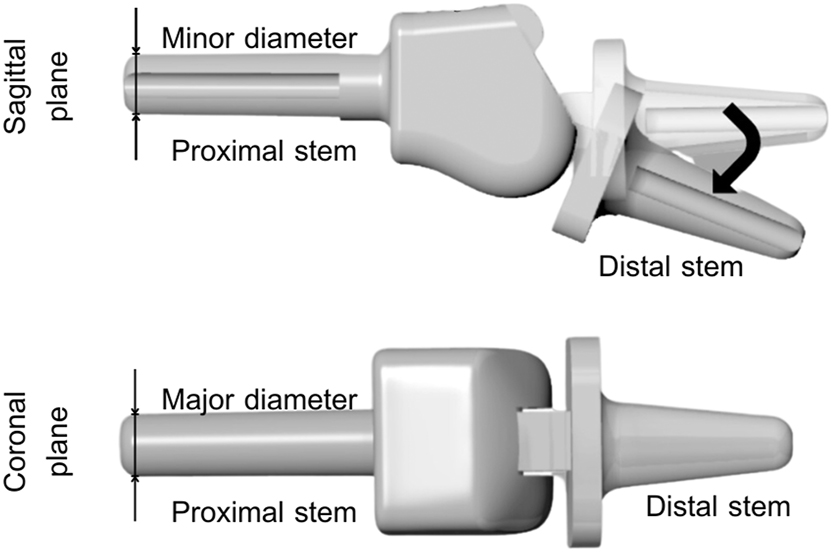
Schematic of the investigated prosthesis that was designed to mimic the range of motion with one degree of freedom movement.
Design dimension of the prosthesis.
| Cadaver 1 | Cadaver 2 | Cadaver 3 | |||||||
|---|---|---|---|---|---|---|---|---|---|
| Index | Middle | Ring | Index | Middle | Ring | Index | Middle | Ring | |
| 1. Distal stem diameter | |||||||||
| – Minor diameter (mm) | 3.53 | 3.53 | 3.53 | 4.31 | 4.31 | 4.31 | 3.59 | 3.59 | 3.59 |
| – Major diameter (mm) | 3.85 | 3.85 | 3.85 | 4.71 | 4.71 | 4.71 | 3.91 | 3.91 | 3.91 |
| 2. Distal stem length (mm) | 8.48 | 8.48 | 8.48 | 10.38 | 10.38 | 10.38 | 8.62 | 8.62 | 8.62 |
| 3. Proximal stem diameter (mm) | 3.00 | 3.00 | 3.00 | 3.62 | 3.62 | 3.62 | 3.00 | 3.00 | 3.00 |
| 4. Proximal stem length (mm) | 11.15 | 11.15 | 11.15 | 13.65 | 13.65 | 13.65 | 11.33 | 11.33 | 11.33 |
| 5. (Before) Hinge roughness (µm) | 3.66 | 3.66 | 3.66 | 3.25 | 3.25 | 3.25 | 3.14 | 3.14 | 3.14 |
The prosthetic components were engineered using grade 23 titanium alloy (medical-grade Ti–6Al–4V extra low interstitial) powder and manufactured through the selective laser melting (i.e. laser powder bed fusion methods (PBF-L/M) technique) on a titanium powder bed, a process facilitated by Meticuly Co., Ltd., headquartered in Singapore. Subsequent refinement procedures involved successive polishing and acid-etching stages aimed at eliminating residual particles and reducing frictional resistance on the joint surface. Following fabrication, a rigorous cleaning protocol utilising ultrasonic oscillations was employed. The final surface roughness (Ra) was controlled to measure 3.69 ± 0.10 µm. The prosthetic components were then dorsally inserted into three distinct cadaveric specimens for subsequent analysis and evaluation, as demonstrated in Figure 2.
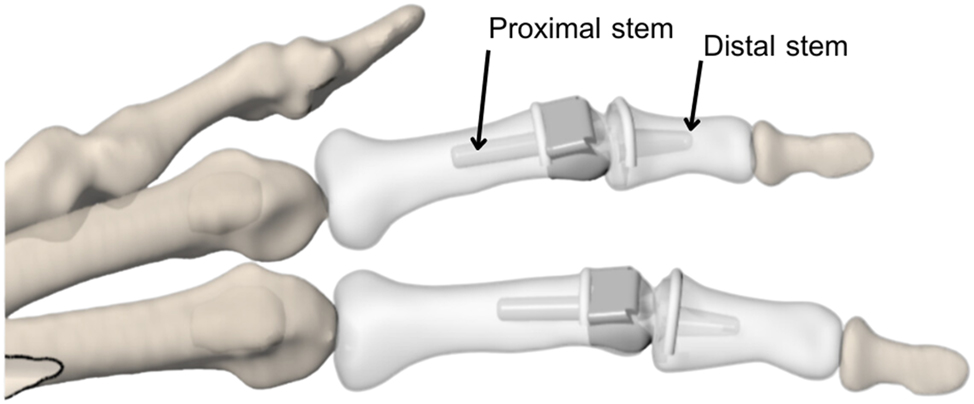
Illustration of the PIP joint when inserted in cadaver between proximal phalanges and intermediate phalanges.
The biomechanical testing of PIP prosthesis was designed to evaluate finger joint movement in dynamic mode. The test setup was aimed to imitate phalanges movement in which the parallel four-bar linkage is employed. The parallel four-bar linkage is employed to mimic the movement of a human joint, as the motion is similar and widely used in finger simulation, robotics and prosthetics [9, 11, 12]. The tendons and muscles affected across the joint were considered and simulated by the device through adjustable strut as described in earlier reports [13], [14], [15].
The finger specimen was embedded into a finger cap and fixed by an adjustable nylon cable tie, which allows the PIP joint to move while restricting the movement of the DIP joint, as shown in Figure 3. In the middle, the connector rod is attached to the driver to line up the mechanism with the phalanges of the hand as shown in Figure 3. The adjustable strut is used so that it can simulate movement in the PIP joint and reflect the different lengths of each finger. The motor was controlled by a programmed circuit board to produce a constant ROM and a constant frequency.
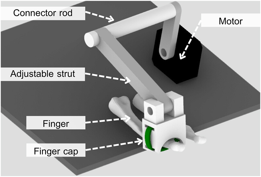
Biomechanical testing apparatus to investigate wear and longevity of finger joints.
The testing device was verified by comparing the four cycles range of motion (ROM) of the PIP joint through motion recording with actual PIP joint movement. Arc of motion between the two extremes under this device was 90° where the actual maximum arc of motion that a PIP joint can flex and extend is up to 110° before hyperextending, but the actual active ROM during everyday use is approximately 0°–90° [16]. The angle of flexion on the dorsal and ventral surface of the PIP joint was measured and averaged using ImageJ software (National Institute of Healths, USA).
The dynamic test was done on index, middle and ring fingers of three aforementioned cadavers, under 50,000 continuous cycles at 3.4 Hz, which is equivalent to 200,000 cycles of normal human finger movement. The surface roughness of articulated components of each prosthesis pre- and post-testing was acquired as the average of 30 linear lines from Profilometer (Keyence VK-X3000, Belgium). All prostheses were removed and virtually examined for surface damage analysis using a digital microscope (Keyence VK-X3000, Belgium).
3 Results and discussion
During the 3D printing process, particularly with techniques such as selective laser melting (SLM) employed for fabricating titanium prostheses, structures with desirable mechanical properties can be achieved, similar to other studies [17, 18]. However, in cyclical loading, concerns regarding fatigue resistance persist and draw attention to the printing process and subsequent heat treatment process. To establish assurance regarding fatigue resistance and desirable mechanical properties, a stringent acceptance criterion on 99.0 % or higher for density was set. The following tests were administered: optical metallography investigation, SEM micrograph analysis and Archimedes density measurement.
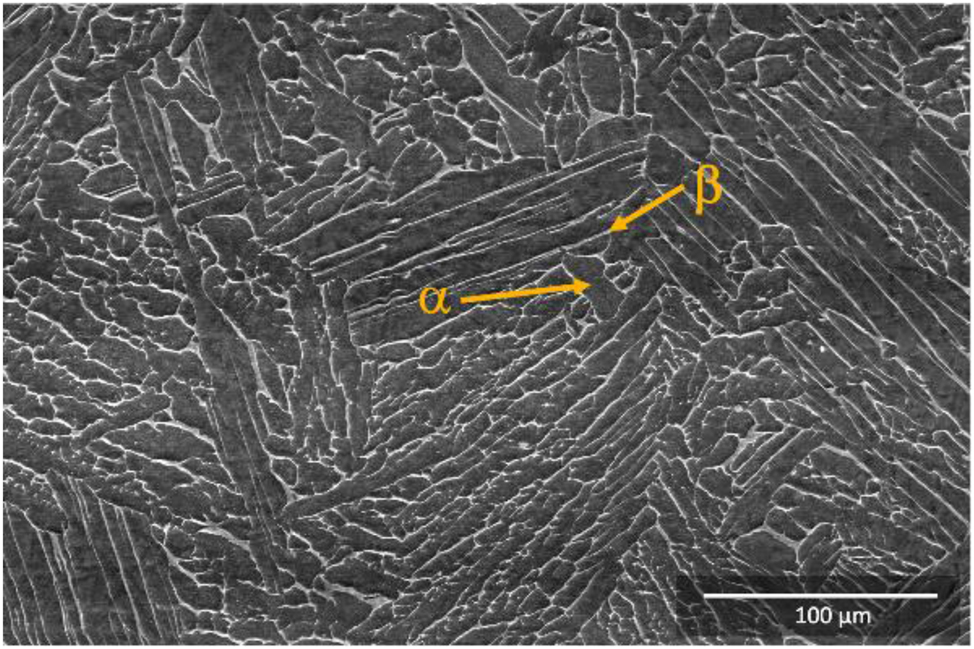
All optical metallography images and SEM micrographs revealed the microstructure of 3D-printed titanium to be fully dense. No pores or defects were found in the areas investigated. As shown in Figures 4 and 5, SEM secondary electron micrographs indicated fully dense in the magnification shown. As-printed Ti6Al4V ELI specimen is shown in Figure 4, consisting of fine acicular martensite domain, α′ phase, inside the prior β grain which formed along with build direction. The α′ phase has high ultimate tensile strength but very low ductility. Accordingly, the heat treatment at below β-transus temperature was performed to improve the ductility by inducing the phase transformation from α′ to α + β phase, which can be observed in other studies [19].
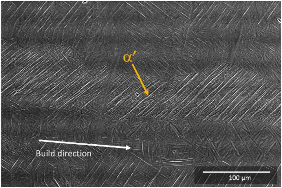
Secondary electron micrographs of as-printed Ti6Al4V ELI specimen revealed the microstructure consisting of two phases, which are the α′ phase as fine acicular martensite needles inside the prior β grain that formed along with build direction.
Secondary electron micrograph of heat treated Ti6Al4V ELI (the dark regions were α phase and the lighter regions were β phase along the grain boundary, there is no longer textured orientation and in overall the microstructure was fully dense and free of defects).
In Figure 5, the microstructure of heat treated Ti6Al4V ELI specimen confirmed coarser features, as shown are α (alpha) phase representing the darker contrast region and β (beta) phase as the lighter contrast along the grain boundary. In both SEM micrographs, keyhole defects or lack of fusion defects were not detected. Archimedes density measurements were averaged to be 99.08 % ± 0.06 % to confirm the dense appearance as observed in the SEM. Porosity and defects within the printed structure can act as stress concentrators, potentially reducing fatigue resistance. Careful control of printing parameters and thorough inspection can mitigate the presence of defects.
Grain texture was found in the as-printed microstructure following print direction and heat flow direction. Texture was no longer detected after the heat treatment. The transformation is an indication that the residual stress that was accumulated during the laser printing had been relieved. Residual stresses arising during the printing process may affect fatigue behaviour. Proper heat treatments and stress-relieving procedures can be employed to minimise residual stresses and enhance fatigue resistance.
Onto the 3D-printed prostheses, as they were surgically replaced into cadavers’ fingers, the fingers were then subjected to the range of motion (ROM) simulator. The arc of motion between flex and extend position was measured to verify the ROM of the testing device to mimic the PIP joint. After using ImageJ software to find the average ROM of the joint simulation prototype for four cycles, it was found that on average the prototype was able to flex and extend the human PIP joint at an average of 1.90° ± 1.12°–90.13° ± 1.81°. This deviates slightly from the set range of 0°–90°, with the percentage error being 1.05 % for the minimum angle of flexion (0°), and the percentage error being 1.07 % for the maximum angle of flexion (90°). This verified the ROM of the testing device to be close to the average ROM of a human PIP joint during everyday use, which is 0°–90° [16].
The articulated hinge area of the prosthesis is designed to slide against each other, resulting in an increase of friction at the surface of the hinge. Surface topography of the hinge area before and after 50,000 continuous cycles of index, middle and ring fingers is shown in Figure 6, 7, and 8, respectively. The scratch marks pattern distributed homogeneously on the contact surfaces were similar over all three protheses and indicated wear on the counterface. This is correlated with wear of metal-on-metal joints. Striation and burnishing can be observed on the contacted surfaces, which is similar to light scratches to other studies [20]. Changes in size, shape, pitting and fretting were not observed at macroscopic level.
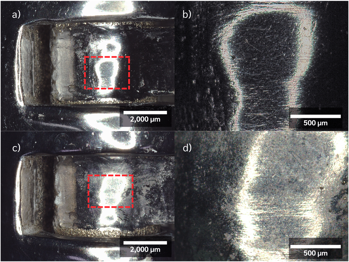
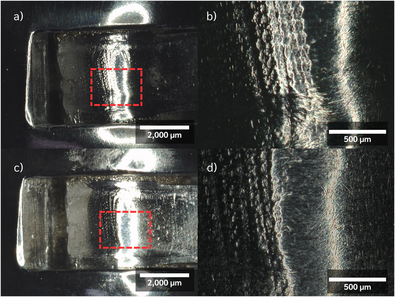
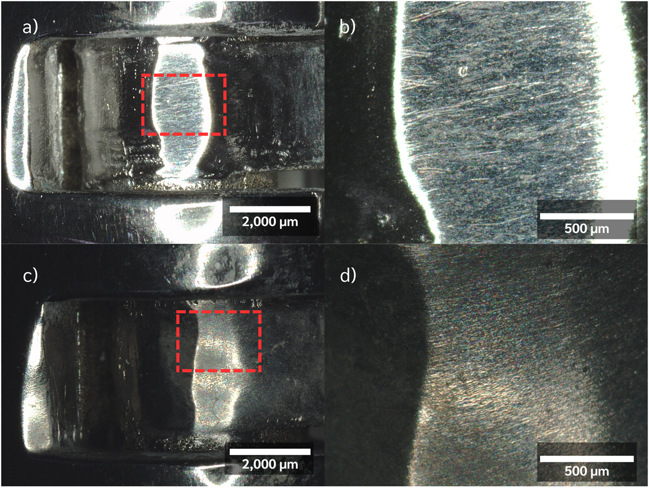
The surface roughness of the articulated area was measured and is shown in Figure 9. All three fingers showed a decrease in average surface roughness with differences of 0.67 ± 1.31, 0.97 ± 1.20 and 0.52 ± 0.10 µm, compared to the average surface roughness before the test in index, middle and ring fingers, respectively. The decrease in average surface roughness is similarly shown in other studies [21]. Middle finger showed the largest roughness difference, which is due to the anatomical differences in the index finger, which is both longer and exerts more force than the middle and ring fingers. The roughness values were in acceptable range for prosthesis usage. However, further studies are required, for example, to investigate the metal debris and to compare with the lifetime of silicone joints.
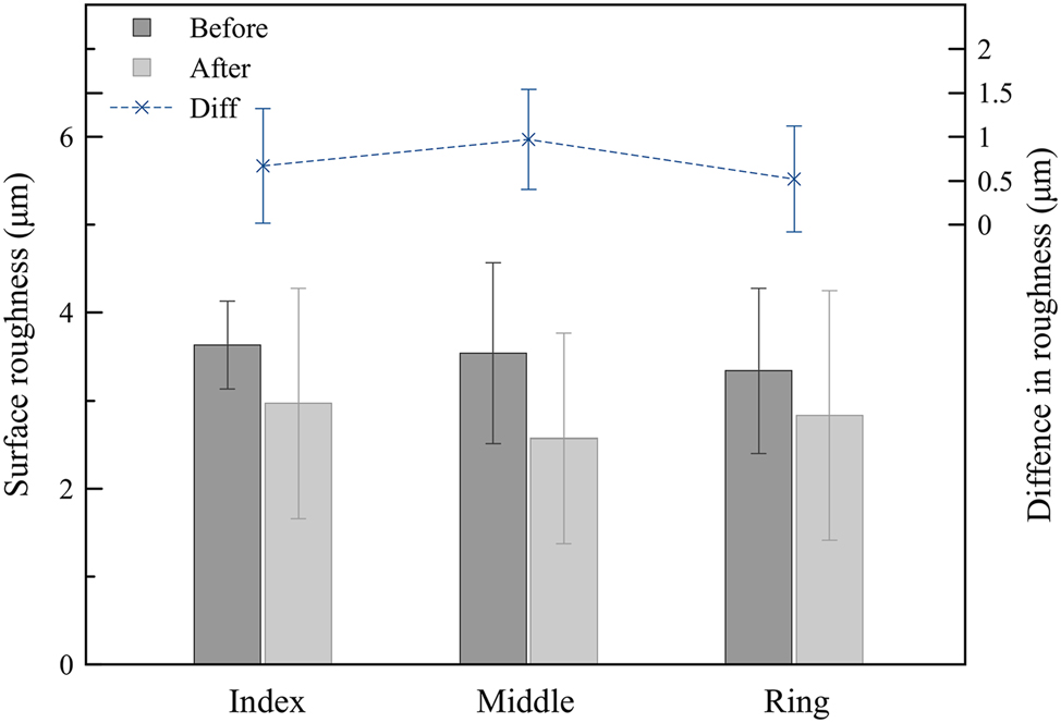
Average surface roughness on the articulated surface of each finger was measured for before and after the 50,000 continuous cycles of dynamic test at 3.4 Hz.
4 Conclusions
Additively manufactured Ti6Al4V ELI prosthesis for PIP joints were manufactured, studied and validated for performance. The demonstrated workflow is an essential first step towards assuring the quality of implantable devices and their longevity in future clinical investigation. SEM micrographs revealed textured microstructure of acicular α′ phase inside β grains in as-printed specimens and homogeneous microstructure of α and β in heat-treated specimens. 3D built density was found to be above 99 %. The range of motion simulator was constructed with four-bar linkage construction and cadaveric investigation of inter-linked PIP joints were performed up to 200,000 cycles. The roughness of the articulated and contacted surfaces improved in many cases similar to the mechanical peening effect. Linked PIP joints are particularly useful when soft tissues such as ligament, tendon and muscles are weak; hence, the interlocked joint could raise joint stability.
About the authors
Panaruj Bussayasripatt is a senior high school student at International School of Bangkok (ISB), Nonthaburi, Thailand. He worked as an intern at Meticuly.
Kitti Poungsiri graduated from the Department of Mechanical engineering at Kasetsart University. He is working at Meticuly Co.Ltd Bangkok, Thailand as a design engineer in a Biomechanic laboratory, Meticuly.
Chetarpa Yipyintum graduated from the Department of Metallurgical engineering, Chulalongkorn University, Bangkok, Thailand. She’s working at Meticuly Co.Ltd Bangkok, Thailand as a research engineer in a Biomechanic laboratory, Meticuly.
Chris Charoenlap is an orthopaedic surgeon at the Department of Orthopaedics, Faculty of Medicine, Chulalongkorn University, Bangkok, Thailand.
Chindanai Hongsaprabhas is an orthopaedic surgeon at the Department of Orthopaedics, Faculty of Medicine, Chulalongkorn University, Bangkok, Thailand.
Kawee Pataradool is an orthopaedic surgeon at the Department of Orthopaedics, Faculty of Medicine, Chulalongkorn University, Bangkok, Thailand.
Thanawat Tantimethanon is an orthopaedic surgeon at the Department of Orthopaedics, Faculty of Medicine, Chulalongkorn University, Bangkok, Thailand.
Thanawat Phetrattanarangsi is a PhD candidate in 3D Laboratory, Department of Metallurgical Engineering, Chulalongkorn University, Bangkok, Thailand.
Chedtha Puncreobutr is an Assistant Professor in Department of Metallurgical Engineering, Chulalongkorn University, Bangkok, Thailand.
Boonrat Lohwongwatana is an Associate Professor in Department of Metallurgical engineering, and Director of Biomedical Engineering Research Center, Chulalongkorn University, Bangkok, Thailand.
Acknowledgment
The authors extend their gratitude to Chulalongkorn University’s ‘Chula Soft Cadaver Surgical Training Center’ and the body donors are greatly appreciated. Their contributions were essential to the successful execution of this research and training of expert surgeons. Furthermore, the financial support received from Chulalongkorn Academic Advancement into its 2nd Century Project, Phase 2, at Chulalongkorn University, Thailand, is acknowledged.
-
Research ethics: The institutional review board (IRB) of the Faculty of Medicine, Chulalongkorn University (Bangkok, Thailand) approved this study (IRB No. 617/64), titled “A biomechanic cadaveric study of 3D-printed endoprosthesis prototype at middle phalanx of hand.”
-
Author contributions: Panaruj Bussayasripatt is a senior high school student at International School of Bangkok, Nonthaburi, Thailand. Kitti Poungsiri graduated from the department of mechanical engineering at Chulalongkorn University. He is working at Meticuly Co.Ltd Bangkok, Thailand as a design engineer in a Biomechanic laboratory. Chetarpa Yipyintum graduated from the department of metallurgical engineering, Chulalongkorn University, Bangkok, Thailand. She’s working at Meticuly Co.Ltd Bangkok, Thailand as a research engineer in a Biomechanic laboratory. Chris Charoenlap is an orthopaedic surgeon at the department of Orthopaedics, Faculty of Medicine, Chulalongkorn University, Bangkok, Thailand. Chindanai Hongsaprabhas is an orthopaedic surgeon at the department of Orthopaedics, Faculty of Medicine, Chulalongkorn University, Bangkok, Thailand. Kawee Pataradool is an orthopaedic surgeon at the department of Orthopaedics, Faculty of Medicine, Chulalongkorn University, Bangkok, Thailand. Thanawat Tantimethanon is an orthopaedic surgeon at the department of Orthopaedics, Faculty of Medicine, Chulalongkorn University, Bangkok, Thailand. Thanawat Phetrattanarangsi is an PhD student in Advanced Material Analysis Research Unit, Department of Metallurgical Engineering, Chulalongkorn University, Bangkok, Thailand. Chedtha Puncreobutr is an Assistant Professor in department of metallurgical engineering, Chulalongkorn University, Bangkok, Thailand. Boonrat Lohwongwatana is an Associate Professor in Biomedical Engineering Research Center, Chulalongkorn University, Bangkok, Thailand.
-
Competing interests: The authors state no conflict of interest.
-
Research funding: None declared.
-
Data availability: The raw data can be obtained on request from the corresponding author.
References
[1] I. Gibson, S. P. Chow, K. M. Lam, et al.., “The development of an artificial finger joint,” in Bio-Materials and Prototyping Applications in Medicine, P. Bártolo, and B. Bidanda, Eds., Boston, MA, Springer US, 2008, pp. 157–190.10.1007/978-0-387-47683-4_9Suche in Google Scholar
[2] A. B. Swanson, “Flexible implant arthroplasty for arthritic finger joints: rationale, technique, and results of treatment,” J. Bone Joint Surg. Am., vol. 54, no. 3, pp. 435–455, 1972. https://doi.org/10.2106/00004623-197254030-00001.Suche in Google Scholar
[3] M. Skie, N. Gove, and D. Ciocanel, “Intraoperative fracture of a pyrocarbon PIP total joint—a case report,” Hand, vol. 2, no. 3, pp. 90–93, 2007, https://doi.org/10.1007/s11552-007-9027-5.Suche in Google Scholar PubMed PubMed Central
[4] B. Weightman, S. Simon, R. Rose, I. Paul, and E. Radin, “Environmental fatigue testing of silastic finger joint prostheses,” J. Biomed. Mater. Res., vol. 6, no. 4, pp. 15–24, 1972, https://doi.org/10.1002/jbm.820060404.Suche in Google Scholar PubMed
[5] D. E. Foliart, “Swanson silicone finger joint implants: a review of the literature regarding long-term complications,” J. Hand Surg. Am., vol. 20, no. 3, pp. 445–449, 1995, https://doi.org/10.1016/S0363-5023(05)80104-2.Suche in Google Scholar PubMed
[6] S. Rath, “Hand kinematics: application in clinical practice,” Indian J. Plast Surg., vol. 44, no. 2, pp. 178–185, 2011, https://doi.org/10.4103/0970-0358.85338.Suche in Google Scholar PubMed PubMed Central
[7] M. Domalain, P. J. Evans, W. H. Seitz, and Z.-M. Li, “Influence of index finger proximal interphalangeal joint arthrodesis on precision pinch kinematics,” J. Hand Surg. Am., vol. 36, no. 12, pp. 1944–1949, 2011, https://doi.org/10.1016/j.jhsa.2011.09.010.Suche in Google Scholar PubMed PubMed Central
[8] Y. Yun, P. Agarwal, J. Fox, K. E. Madden, and A. D. Deshpande, “Accurate torque control of finger joints with UT hand exoskeleton through Bowden cable SEA,” in 2016 IEEE/RSJ International Conference on Intelligent Robots and Systems (IROS), 2016, pp. 390–397.10.1109/IROS.2016.7759084Suche in Google Scholar
[9] K. Xia, X. Chen, X. Chang, et al.., “Hand exoskeleton design and human–machine interaction strategies for rehabilitation,” Bioengineering, vols. 9–11, 2022, Art. no. 11, https://doi.org/10.3390/bioengineering9110682.Suche in Google Scholar PubMed PubMed Central
[10] H. Eschmann, M. E. Héroux, J. H. Cheetham, S. Potts, and J. Diong, “Thumb and finger movement is reduced after stroke: an observational study,” PLoS One, vol. 14, no. 6, p. e0217969, 2019, https://doi.org/10.1371/journal.pone.0217969.Suche in Google Scholar PubMed PubMed Central
[11] K. Y. Choi, A. Akhtar, and T. Bretl, “A compliant four-bar linkage mechanism that makes the fingers of a prosthetic hand more impact resistant,” in IEEE International Conference on Robotics and Automation: ICRA, Proc. of IEEE Int Conf Robot Autom, vol. 2017, pp. 6694–6699, 2017.10.1109/ICRA.2017.7989791Suche in Google Scholar PubMed PubMed Central
[12] M. A. Abdul Wahit, S. A. Ahmad, M. H. Marhaban, C. Wada, and L. I. Izhar, “3D printed robot hand structure using four-bar linkage mechanism for prosthetic application,” Sensors, vol. 20, no. 15, 2020, Art. no. 15, https://doi.org/10.3390/s20154174.Suche in Google Scholar PubMed PubMed Central
[13] D. Hu, D. Howard, and L. Ren, “Biomechanical analysis of the human finger extensor mechanism during isometric pressing,” PLoS One, vol. 9, no. 4, p. e94533, 2014, https://doi.org/10.1371/journal.pone.0094533.Suche in Google Scholar PubMed PubMed Central
[14] S. Kamnerdnakta, H. E. Huetteman, and K. C. Chung, “Complications of proximal interphalangeal joint injuries: prevention and treatment,” Hand Clin., vol. 34, no. 2, pp. 267–288, 2018, https://doi.org/10.1016/j.hcl.2017.12.014.Suche in Google Scholar PubMed PubMed Central
[15] K. J. Bretz, Á. Jobbágy, and K. Bretz, “Force Measurement of Hand and Fingers,” Biomechanica Hungarica., vol. 3, no. 1, pp. 61–66, 2010. https://doi.org/10.17489/biohun/2010/1/07.Suche in Google Scholar
[16] P. Brüser, T. Poss, and G. Larkin, “Results of proximal interphalangeal joint release for flexion contractures: midlateral versus palmar incision,” J. Hand Surg. Am., vol. 24, no. 2, pp. 288–294, 1999, https://doi.org/10.1053/jhsu.1999.0288.Suche in Google Scholar PubMed
[17] E. Savran, O. C. Kalay, N. B. Alp, and F. Karpat, “Design and analysis of lattice structure applied humerus semi-prosthesis,” Mater. Test., vol. 65, no. 7, pp. 1039–1055, 2023, https://doi.org/10.1515/mt-2022-0408.Suche in Google Scholar
[18] A. Muthuchamy, P. Patel, M. Rajadurai, J. K. Chaurisiya, and A. R. Annamalai, “Influence of sintering temperature on mechanical properties of spark plasma sintered pre-alloyed Ti-6Al-4 V powder,” Mater. Test., vol. 60, no. 3, pp. 283–288, 2018, https://doi.org/10.3139/120.111149.Suche in Google Scholar
[19] M. Altuğ, “Investigation of material removal rate (MRR) and wire wear ratio (WWR) for alloy Ti6Al4 V exposed to heat treatment processing in WEDM and optimization of parameters using Grey relational analysis,” Mater. Test., vol. 58, no. 9, pp. 794–805, 2016, https://doi.org/10.3139/120.110916.Suche in Google Scholar
[20] M. C. Bone, G. Giddins, and T. J. Joyce, “An analysis of explanted pyrolytic carbon prostheses,” J. Hand Surg. Eur. Vol., vol. 39, no. 6, pp. 666–667, 2014, https://doi.org/10.1177/1753193412469134.Suche in Google Scholar PubMed
[21] T. J. Joyce, “Wear testing of a DJOA finger prosthesis in vitro,” J. Mater. Sci. Mater. Med., vol. 21, no. 8, pp. 2337–2343, 2010, https://doi.org/10.1007/s10856-010-4010-z.Suche in Google Scholar PubMed
© 2023 the author(s), published by De Gruyter, Berlin/Boston
This work is licensed under the Creative Commons Attribution 4.0 International License.
Artikel in diesem Heft
- Frontmatter
- Performance of additively manufactured Ti6Al4V ELI finger joints: biomechanical testing and evaluation for arthritis management
- Mechanical and microstructural characterization of resistance spot welded dissimilar TWIP1000/TRIP800 joints
- Effect of particle size on the properties of avocado pear wood fiber/low-density polyethylene composite enhanced by pretreatment
- Design optimization of hybrid material B-pillar under crush loading
- Pack-boriding of Sleipner steel: microstructure analysis and kinetics modeling
- Structural comparison of conventional and chiral auxetic morphed aircraft rib
- Compression behavior of the wood-inspired cellular structure of acrylonitrile butadiene styrene
- Adhesive wear behavior and microstructure of FeCr–FeMn–FeB–C coatings
- Dry sliding wear behavior of AA7075 alloy produced by thixocasting
- Effects of compaction pressure on microstructure, mechanical properties, and machining characteristics of sintered AISI 316L steel
- Investigation of the effects of halloysite nanoclay on friction and wear behavior of automotive brake pads
- Identifying stir casting process parameters to maximize strength of LM13 with TiB2 and ZrC hybrid metal matrix composite
- Effect of gas metal arc and cold metal transfer arc welding processes on microstructure and mechanical properties of AA8011-H18 alloy joints
- Anisotropy effects on the tensile properties of AA5052 and AA5052-PVC-AA5052 sandwich sheets