An atomistic study on the strain rate and temperature dependences of the plastic deformation Cu–Au core–shell nanowires: On the role of dislocations
-
Ibrahim Abdulwahhab Atiyah
 und
Raed Kadhim Mohammed Jawad
und
Raed Kadhim Mohammed Jawad

Abstract
Recently, Cu–Au core–shell nanowires have been extensively used as conductors, nanocatalysts, and aerospace instruments due to their excellent thermal and electrical conductivity. In experimental studies, various methods have been presented for producing, characterizing, and strengthening these structures. However, the mechanical behavior and plastic deformation mechanisms of these materials have not been investigated at the atomic scale. Consequently, in the present study, we carried out uniaxial tensile tests on Cu–Au nanowires at various tension rates and temperatures by means of the molecular dynamics approach. The Cu–Au interface was found to be the main site for nucleation of perfect dislocations, Shockley partials, and stacking faults due to the stress concentration and high potential energy arising from the atomic mismatch between shell and core layers. It was observed that an increase in the strain rate from 108 to 1,011 s−1 shortened the time required for the nucleation of dislocations, decreasing the dislocation density. This emphasizes that dislocation nucleation and slip mechanisms are time-dependent. Moreover, it was found that the interaction of Shockley partials can lead to the creation of lock dislocations, such as Hirth, Frank, and Stair-rod dislocations, imposing obstacles for the slip of other dislocations. However, as the tension temperature rose from 300 to 600 K, opposite-sign dislocations removed each other due to thermally activated mechanisms such as dislocation climb and dislocation recovery. Furthermore, the combination of Shockley partial dislocations decreased the stacking fault density, facilitating the plastic deformation of these structures. The yield strength and elastic modulus of the samples increased with the strain rate and substantially decreased as the temperature rose.
1 Introduction
Cu–Au core–shell nanowires are of great attention in electrics, medicine, and aerospace in light of their great electrical conductivity, high specific strength, desirable thermal conductivity, and thermal stability at high temperatures [1]. To fabricate such nanomaterials, a core with a certain design and thickness is fabricated. Then, the shell structure is deposited with a predefined orientation on the core [2,3]. The shell–core interface of such nanowires is a determinant of their strength and expected properties [4]. Stewart et al. reported that Cu–Au core–shell nanowires have a high potential to serve as electrical conductors and enjoy excellent thermal conductivity [5]. Also, Zhang et al. found that Cu–Au core–shell nanowires could be employed in electrochromic energy storage devices [6]. Research conducted earlier has shown that molecular dynamics (MD) simulations and the Monte Carlo method are efficient methods to examine the mechanical features and plastic behavior of nanometers at an atomistic scale [7,8]. Additionally, recent research has proved that MD simulations are efficient enough in determining the interface coherency and its role in the properties of core–shell nanostructures [9,10]. Drawing on MD, crystallographic defects in microstructures could be captured at the atomic scale [11]. It is important to explore the mechanical features of core–shell structures in the sense that such structures are mostly under tensile, compressive, and shear loads in service. Dislocations, stacking faults, and twins have been found to be major defects in crystalline structures and influence the mechanical properties of metal nanomaterials under mechanical loadings [12,13]. Abaid Samawi et al. (2022) evaluated the plastic deformation mechanisms of pure Cu and Au nanowires under uniaxial tension. They observed that dislocation deformations were the main explanation for the deformation of Cu and Au nanowires; however, twins were also observed at the final stage of deformations. It is worth noting that twin deformations were greater than in conventional body-centered cubic and hexagonal closest packed (HCP) metals [14].
Several factors, including the strain rate, the geometry of the sample, the type of loading, and temperature, have significant effects on such microstructural defects [15]. Sarkar and Das studied Cu–Au core–shell nanostructures and showed that an increase in the thickness of the shell layer above 10 nm increased dislocation tangling, enhancing the yield strength of the sample [16]. However, a further rise in the thickness above 15 nm had no contribution to the dislocation density. Santhapuram et al. demonstrated that the shell thickness was not an influential parameter in the early stages of plastic deformation, whereas the nature of the interface was the major determinant of dislocation nucleation [17]. Hence, it can be concluded that the core and shell thicknesses are crucial in evaluating the mechanical features and plastic deformation behavior of such nanostructures.
However, for core–shell nanostructures, the interface nature is a major determinant of mechanical properties. Ke and Mastorakos [18] studied semi-coherent Au–Ni and Cu–Ni core–shell structures and showed that a majority of misfit dislocations in the structures with a semi-coherent interface were the main explanation for the emission of dislocations in the shell structure. However, the semi-coherent interfaces could function as a permanent obstacle to dislocation transmission from the core into the shell or vice versa. Earlier works [19,20,21] investigated metal/metal core–shell structures and found that tangling of dislocations in the interface was an important contributor to enhancing the mechanical features. Niu et al. [1] investigated different morphologies of Cu/Cu core–shell structures using MD. Recent studies introduced methods to enhance the strength, electrical conductivity, and chemical reactivity of Cu/Au core–shell catalysts [22]. Yin et al. [23] studied the synthesis stages and characterization of Cu–Au nanoparticles with a core–shell nanostructure.
As mentioned earlier, the mechanical features of the Cu–Au core–shell nanowires are affected by both strain rate and temperature. This is particularly relevant because these nanowires are commonly utilized as materials with exceptionally high thermal conductivity. Trong et al. argued that Cu, Au, and their alloys have excellent thermal and electrical conductivity [24]. Therefore, it is necessary to evaluate the effects of temperature on their microstructures at high temperatures. It should be noted that atomic disorders within the microstructures of these materials change their thermal conductivity [25,26]. Moreover, the strain rate is a major factor that alters the microstructure of such nanowires. For example, Abd-Alkuder Salman et al. (2023) studied the effects of tension rate on pure Au nanowires using uniaxial tensile simulations. They found that the plastic behavior of pure Au nanowires displays three distinct types at various strain rate ranges [27]. Hence, this study focuses on the effects of strain rate and temperature on microstructure, deformation mechanisms, and mechanical properties of Cu–Au core–shell nanostructures at the atomistic scale.
To explore the temperature effects on the mechanical features of Cu–Au core–shell nanowires, the temperature range should be below the recrystallization temperature. Wu and Jiang argued that Cu and Au are recrystallized above 700 K [28]. The microstructure of such structures should be maintained at high temperatures to improve thermal conduction. According to the study by Wu and Jiang [28], the temperature range adopted for the present study was below 700 K. Recrystallization would change the regular atomic structure into an irregular structure, reducing the fraction of face-centered cubic (FCC) atoms. This is attributed to the phase transition temperature range [29], which was studied in detail for Cu–Au alloys by Quoc et al.
A review of the literature on Cu–Au core–shell nanostructures suggests that many studies have investigated the synthesis, diffusion, and thermal and electrical conduction characteristics of such nanostructures. Furthermore, a number of studies adopted MD and evaluated the mechanical properties of pure copper and gold nanostructures [30,31]. Catenacci et al. studied the mechanical features of Cu–Au core–shell nanowire composites [32]. Kim et al. mentioned the excellent biocompatibility of Cu–Au core–shell nanostructures [33]. Plastic deformation, however, is not acceptable in these medical implants [34]. The mechanical behavior of Cu–Au core–shell nanostructures has not been studied from the perspective of interface effects on mechanical behavior and properties. Moreover, an atomic mismatch between Cu and Au layers at the interface area could strongly influence the crystallographic defect density. Hence, the present study evaluated the interface effects on the type and density of crystallographic defects within the core and shell areas at different temperatures and strain rates under uniaxial tensile loading. Therefore, Section 2 describes the details of the MD simulation and sample construction. After the model-building step, the samples were subjected to the uniaxial tensile test at different strain rates at room temperature; then, the uniaxial tension was applied at the lowest tension rate and various temperatures to capture the temperature effects on the mechanical features and plastic deformation mechanisms; Section 3 discusses the obtained outcomes; and Section 4 concludes the present work.
2 MD details
2.1 Sample fabrication and tensile test
In this study, we considered the same thicknesses for the core and shell layers of the nanowire models to explore the role of the interface and microstructural defects in the mechanical features and plastic deformation mechanisms of Cu–Au core–shell structures. To create core–shell nanowire samples using Atomsk software [35], an Au cylinder having a diameter of 5 nm and a total length of 10 nm was considered. Then, a Cu shell with a thickness of 2.5 nm and a length of 10 nm was covered over the Au core, as shown in Figure 1.
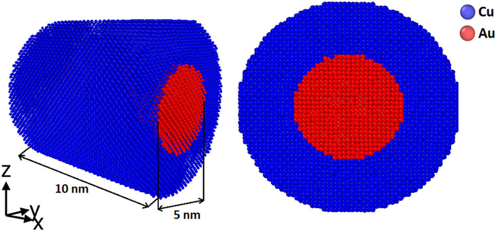
Initial configuration of Cu–Au core–shell nanowires.
In this sample, the core and shell layers have a total of 1,225 Cu atoms and 50,848 Au atoms, respectively. Moreover, the Cu and Au densities were 8.96 and 19.32 g/cm3, respectively. An important point to consider is that the size of a nanosystem is strongly dependent on its mechanical properties [16,36,37]. Therefore, a constant diameter and length were assumed to evaluate the effects of the Cu–Au interface on the formation of crystallographic defects, such as stacking faults and dislocations, at different temperatures so that the size effects on the outputs could be neutralized.
The construction procedure and uniaxial tension were applied via the LAMMPS software [38]. The interactions between Cu–Au, Cu–Cu, and Au–Au particles in the energy and force fields were modeled via the embedded atom model (EAM) [39]. In the EAM potential function, the total energy of atom i is written as follows:
where
In the relaxation step and uniaxial tension, periodic boundary conditions were implemented in all three cartesian directions. The relaxed samples were then subjected to strain-controlled virtual mechanical tension using the fix-deform protocol at the desired temperatures by engineering strain rates of 108–1011 s−1 in the x-direction with a time step of 1 fs. The system pressure was kept zero in lateral directions to implement uniaxial tension. Each sample was simulated three times by defining different initial velocities at the given temperatures and strain rates, and finally, the average results were reported.
2.2 Crystalline structure analysis equipment
In this study, all dislocations were characterized using the dislocation extraction algorithm (DXA) introduced by Stukowski and Albe [43]. To detect the stress concentration at the interface area, von Mises stress analysis was carried out. It should be noted that the von Mises stress criterion is employed to evaluate the plastic deformation of materials. The von Mises criterion can be defined as follows:
where
where
3 Results and discussion
3.1 Mechanical features versus tension rate
To probe the effects of the tension rate on the mechanical features of the Cu–Au core–shell models, the introduced samples experienced uniaxial tensile test at various tension rates at 300 K (see Figure 2 for deformation steps). As strain rises, the sample elongation occurs in the tensile direction, showing softening behavior and no sign of failure. Figure 3a shows the stress–strain curves of the models. As seen, upon passing a linear elastic region, the stresses substantially decreased upon yielding. To calculate the elastic modulus, the linear slope was used at a strain of 2%, as introduced in the study of Li et al. [45]. Furthermore, the average flow stress was calculated in a strain range of 0.2–0.3. As shown in Figure 3b–d, an increase in the tension rate raised the elastic modulus, yield strength, and flow stress. According to the presented stress–strain curves, the plastic region of the stretched sample at the lowest strain rate had a zigzag trend. This has been attributed to the nucleation of SFs [46]. In fact, the formation of SFs is a common process in FCC-based metals because of their low stacking fault energy [47,48,49]. Therefore, it can be concluded that the flow stress is strongly dependent on crystallographic defects, such as twins, SFs, and dislocations.
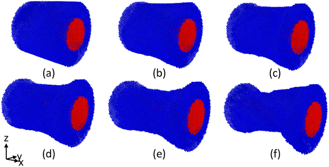
Various stages of the uniaxial tensile loading. (a) ε = 0, (b) ε = 0.05, (c) ε = 0.15, (d) ε = 0.20, (e) ε = 0.25, (f) ε = 0.3.
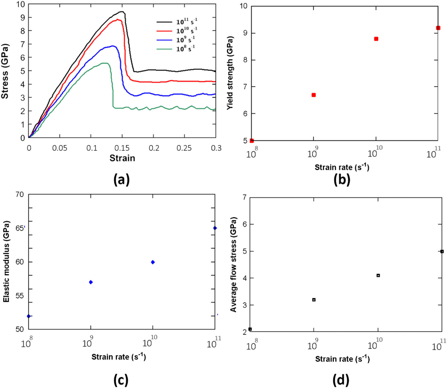
(a) Stress–strain plots of the Cu–Au core–shell nanowires at different strain rates. (b–d) Yield strength, elastic modulus, and average flow stress values.
Based on the previous studies [50,51,52,53,54], dislocations play a crucial role in the plastic deformation of nanocrystalline metals having an FCC structure. However, BCC and HCP metals deform through twins [55,56,57]. As both Cu and Au have FCC crystalline structures, Cu–Au core–shell nanostructures are expected to undergo plastic deformations through the nucleation and slip of dislocations. Zepeda-Ruiz et al. found that the crystalline structure had no defects before the macroscopic yielding. Once yielding occurs, microscopic dislocations nucleate in the microstructure and weaken the elastic strength. An increase in stress raises the dislocation density, and the plastic deformation continues with the slip of dislocations [11].
Figure 4a–d depicts the microstructural defects in the stretched samples at different strain rates. As seen, a dislocation network containing partial and perfect dislocations formed at the Cu–Au interface. Such interfacial dislocations which are well-known as misfit dislocations [59,60] can be observed more clearly in Figure 4a. These dislocations often emit from the interface toward the core. Eftink et al. (2017) studied Cu–Au core–shell nanowires and observed a similar network of dislocations (Figure 4e). According to Figure 4f, transition electron microscope (TEM) images showed perfect and partial dislocations and stacking faults at the Cu–Ag interface [58].
![Figure 4
(a–d) DXA analysis outcomes at yield point for stretched nanowire samples by various strain rates, (e) dislocation formation at the Cu–Ag interface [16], (f) HR-TEM image of dislocations at the Cu–Ag interface [58].](/document/doi/10.1515/jmbm-2022-0296/asset/graphic/j_jmbm-2022-0296_fig_004.jpg)
It can also be inferred that stacking fault planes formed between the two Shockley partial dislocations as the strain rate decreased. Previous studies have shown that dislocation nucleation is a time-consuming process, and a decrease in the strain rate provides a longer time for dislocations to nucleate and increase in density [61]. Sarkar et al. [19] showed that the core–shell interface is the main source of such crystallographic defects in these structures. To explore the effects of the Cu–Au interface on the formation of dislocations, we evaluated the atomic potential energy of atoms and the stress distribution map based on the von Mises criterion at the interface. According to Figure 5a, the atoms at the interface had much higher potential energy than those in the core and shell layers. This arises from the atomic radius difference between Cu and Au atoms, which could concentrate stresses and increase the energy of atoms at the interface. Hence, the Cu–Au interface must be considered the main region for the formation of crystallographic defects during the plastic deformation of Cu–Au core–shell structures. According to Figure 5b, dislocations required lower energy to nucleate at the interface due to the stress concentration. Figure 5c depicts the quantitative analysis of average potential energy and the von Mises stress distribution to better compare different areas of the core–shell nanowire. As can be seen, the interface and shell-free surface have greater stress concentrations than the areas within the core and shell. This can be explained by the fact that surface atoms had higher freedom than atoms within the shell. Furthermore, due to the Cu and Au atomic mismatches, the interface has higher stresses and potential energy than the atoms within the core and shell.
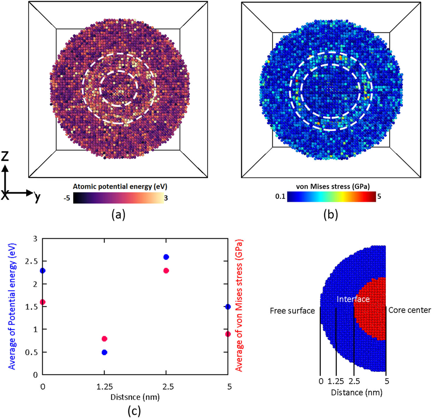
Cross-section of the Cu/Au interfacial region: (a) potential energy analysis, (b) von Mises stress distribution map, (c) quantitative analysis of average potential energy and von Mises stress versus the distance from the core center.
Figure 6a and b compares the dislocation density at different strains for the quantitative analysis of dislocations. As seen, dislocations would not have sufficient time to nucleate at high strain rates, leading to a very low dislocation density. However, the strain rate reduction increases the dislocation density. As seen, the dislocation density is maximized at a strain rate of 108 s−1. As a result, the quantitative results are in line with the qualitative outcomes in Figure 4. It can be concluded that the slip of dislocations and the nucleation of stacking faults are the dominant deformation mechanisms of Cu–Au core–shell structures. Thus, the strain rate plays a crucial role in the microstructural changes and plastic deformation mechanisms of core–shell samples. A comparison of Figure 6a and b also implies that the shell had a greater concentration of dislocations than the core. This could be attributed to the effects of the non-coherent Cu–Au interface, which leads to the emission of most of the dislocations into the shell.
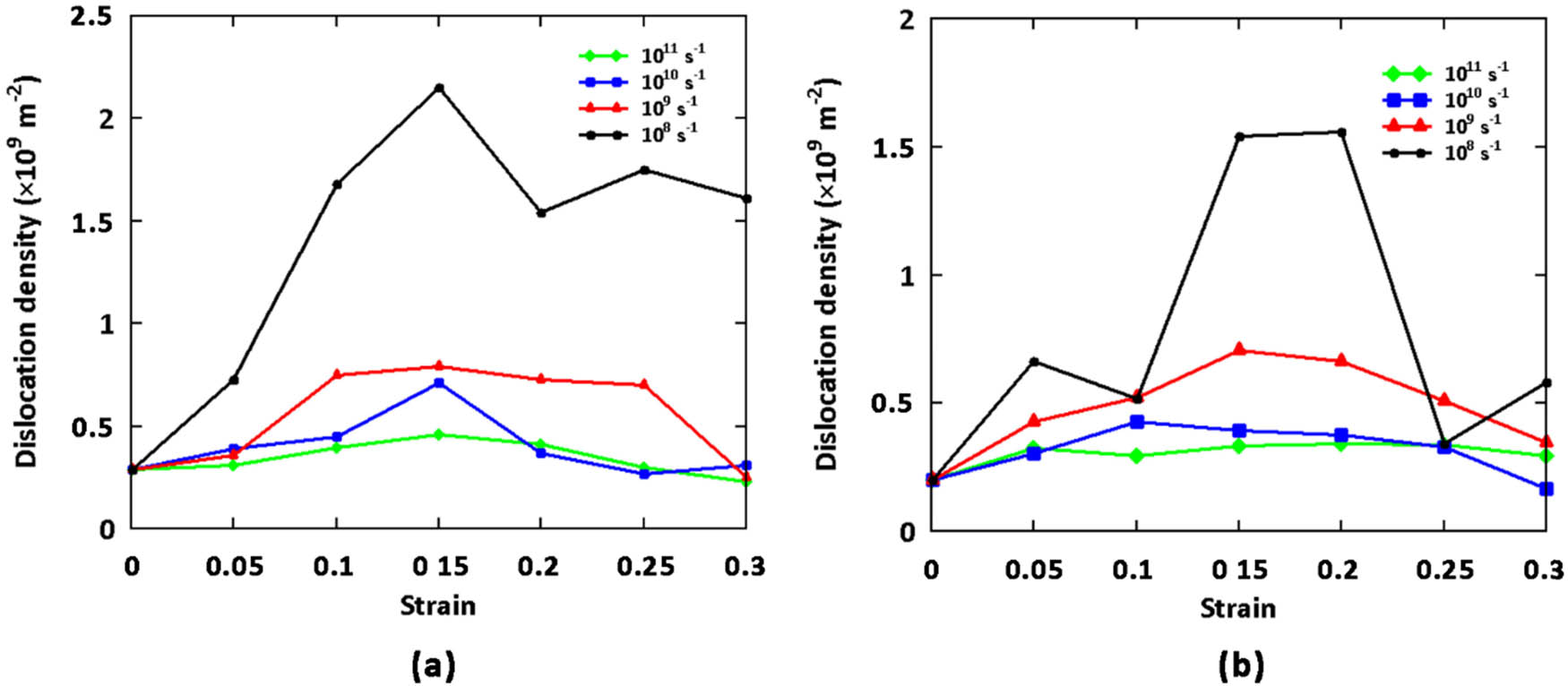
Dislocation density vs strain for Cu–Au core–shell nanowire models under uniaxial tensile test: (a) Cu shell, (b) Au core.
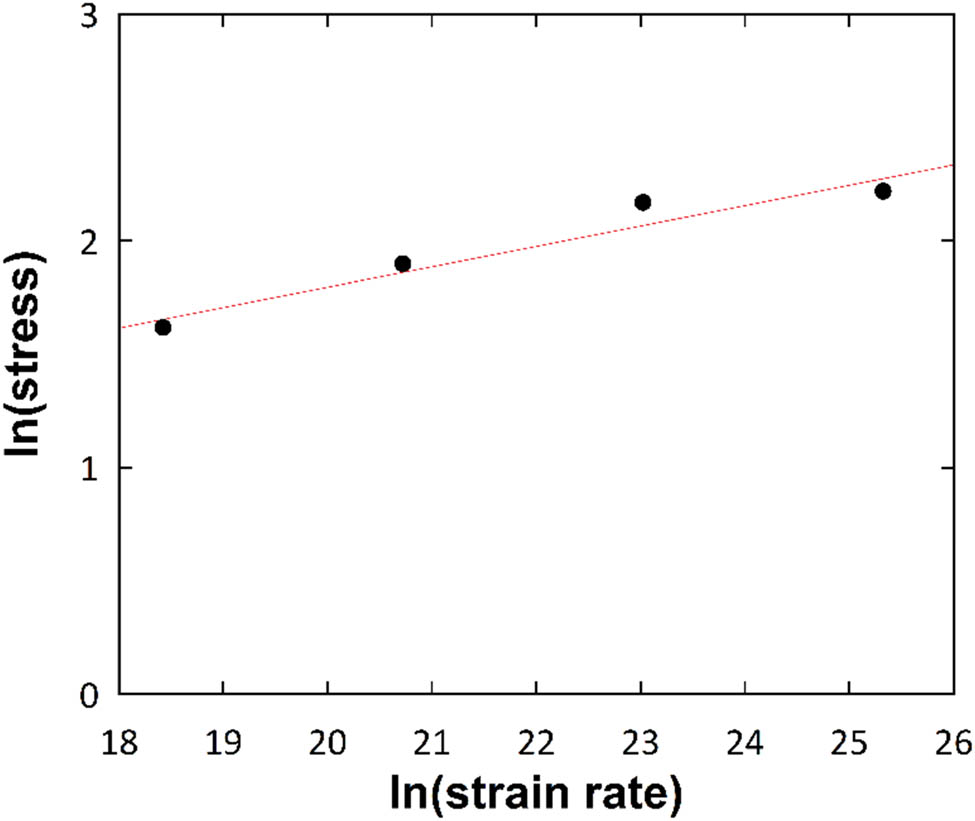
The logarithmic yield strength values versus the logarithmic strain rates.
To further investigate the effects of the tension rate on the stress–strain curve, Figure 7 plots the strain rate sensitivity (SRS) based on a power-law constitutive model [62]. The SRS is defined as follows:
in which
According to Figure 7, the SRS parameter (m) was found to be 0.08. This value deviates significantly from experimental reports, which reported in the range of approximately 0.02–0.04. This could be explained by the sample size, the absence of pre-existing defects, and the high strain rates in the molecular dynamics simulation.
3.2 Mechanical properties versus temperature
In this section, the models were subjected to uniaxial tension at a strain rate of 108 s−1 at 300, 400, 500, and 600 K to explore the effects of the temperature on the mechanical properties and microstructure of Cu–Au core–shell structures. Figure 8 plots the corresponding stress–strain curves. As seen, the rising temperature reduces the yield strength, elastic modulus, and flow stress. Sankaranarayanan et al. [63] found that an increase in temperature raises the motion of atoms due to higher excitation, which may diminish the elastic resistance. It should be noted that the plastic deformation continues with the formation and slip of dislocations based on the zigzag trend of the curves above the yield point in the elastic region. In fact, due to the thermal energy, the energy barrier for dislocation nucleation is expected to decrease.
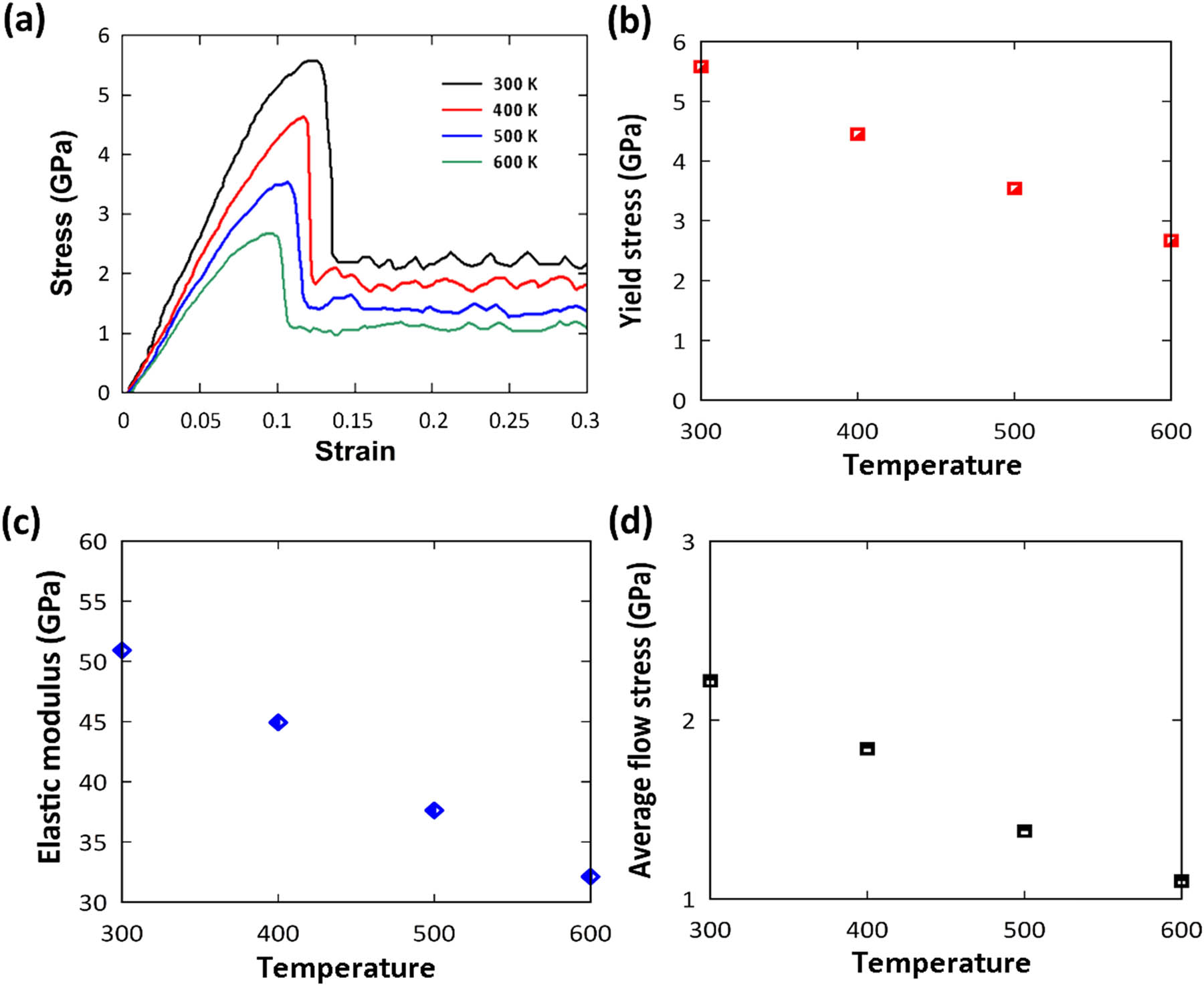
(a) Stress–strain curves of the Cu–Au core–shell nanowires at different temperatures. (b–d) Yield strength, elastic modulus, and average flow stress values.
To further evaluate the temperature-dependent defect evolution of the Cu–Au core–shell samples, Figure 9a–c depicts the dislocations that formed immediately after the samples yielding at 300, 400, and 500 K. As seen, the dislocation density and their tangling increase as the temperature increases. Research has shown that an increase in Shockley dislocation interactions leads to the nucleation of other partial dislocations, such as Hirth, Frank, and stair-rod dislocations, which are immobile within FCC metals [64,65,66]. These dislocations can serve as an obstacle to the slip of other dislocations. Figure 9d shows the dislocations and stacking faults at 600 K. According to Figure 9e, a perfect dislocation was decomposed into two partial dislocations, with stacking faults appearing between two Shockley dislocations based on the following reaction:
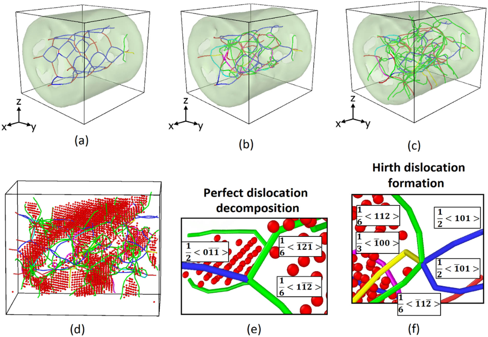
DXA analysis on the creation and expansion of SFs and partial dislocation: (a–c) Showing perfect and partial dislocation networks in Cu–Au nanowire models at 300, 400, and 500 K after yielding. (d) Disclosing stacking faults and Shockley partial dislocation at 600 K. (e) Representing perfect dislocation decomposition. (f) Illustrating Hirth dislocation formation by perfect dislocation interaction.
According to Figure 9f, the interaction of two perfect dislocations leads to two Shockley dislocations and one Hirth dislocation, functioning as a lock dislocation:
Consequently, it can be concluded that temperature affects the formation of defects, particularly dislocations, and can accelerate the deformation of the core–shell models. To quantitatively analyze dislocations, Figure 10 compares the densities of dislocation types at a strain of 0.3 under different temperatures. According to this figure, an increase in the temperature reduced all the dislocations in the samples. This is inconsistent with the presented data concerning dislocation density immediately after yielding in Figure 9. Therefore, it can be deduced that the density of crystallographic defects reduces as the temperature increases at high strain rates. Porter and Easterling [65] described this phenomenon as arising from the activation of dislocation recovery mechanisms, in which opposite-sign dislocations interact and remove each other.
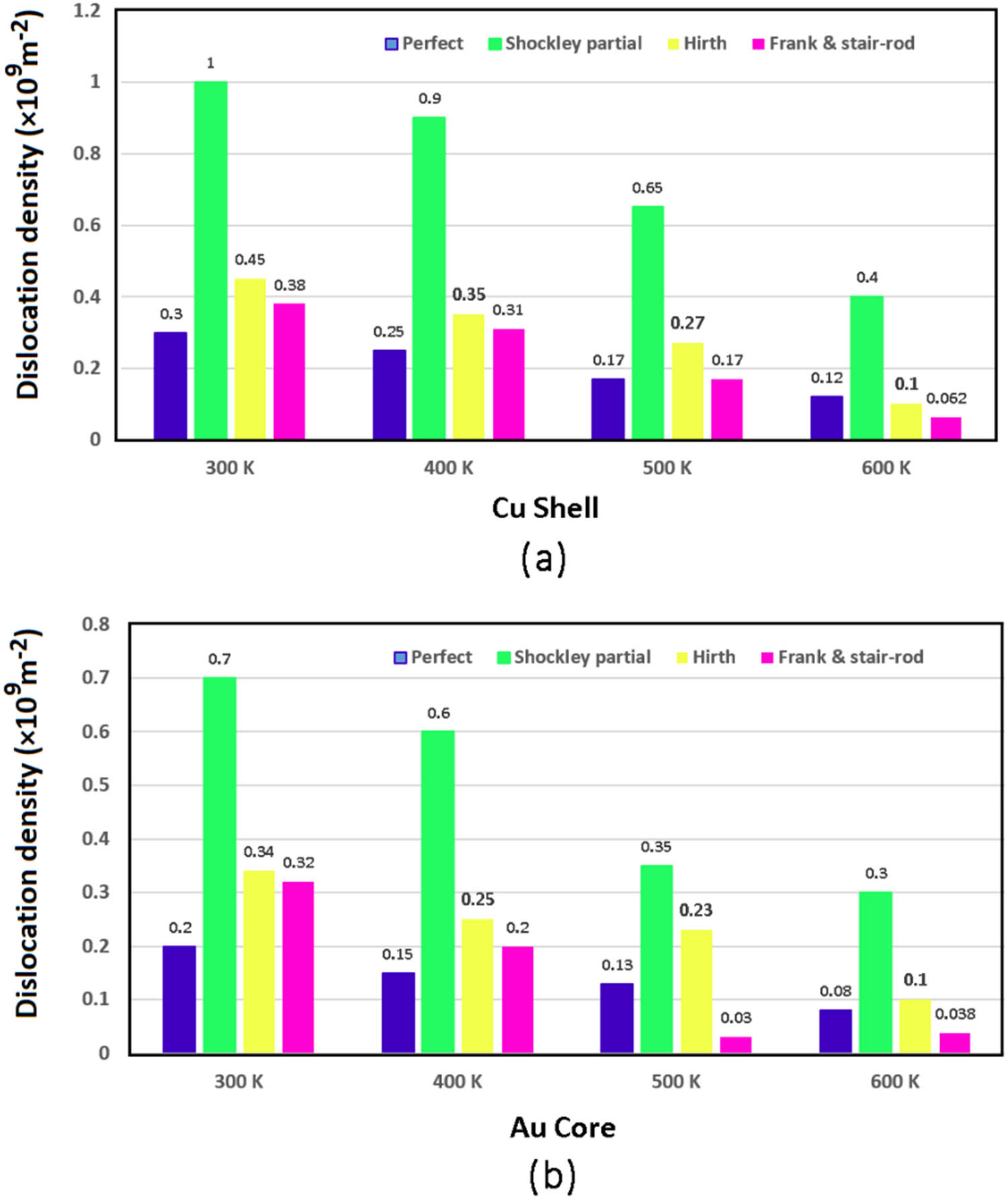
(a) and (b) DXA analysis results represent the effects of tension temperature on the density of dislocations for various types of dislocations at the strain of 0.3 in shell and core layers.
Studies show that temperature-dependent recovery processes may raise the climb of edge dislocations and lead to further plastic deformation [67]. This phenomenon is clearly presented in Figure 10a and b. The instability of stacking faults at high temperatures also affects the dislocation density reduction, as discussed by Zhang and Shibuta [68]. As the temperature rises, stacking faults become unstable and disappear upon the merging of two Shockley partial dislocations. This is the case with both shell dislocations and core dislocations, as shown in Figure 10.
Figure 11a–f shows the step-by-step disappearance of the stacking fault area over time. As can be seen, the number of HCP atoms between two Shockley partial dislocations reduces over time since these dislocations approach each other.
![Figure 11
Snapshots of the stretched sample at 600 K: (a–f) Shockley partial dislocation composition resulting in removing the stacking fault area. (g–i) HRTEM images of step-by-step opposite-sign dislocations removing [69].](/document/doi/10.1515/jmbm-2022-0296/asset/graphic/j_jmbm-2022-0296_fig_011.jpg)
Snapshots of the stretched sample at 600 K: (a–f) Shockley partial dislocation composition resulting in removing the stacking fault area. (g–i) HRTEM images of step-by-step opposite-sign dislocations removing [69].
As mentioned, an increased temperature is the most important driving force for integrating dislocations, where opposite-sign dislocations remove each other. Figure 11g–i shows the HRTEM image of the integration of two opposite-sign dislocations in the FCC crystalline structure of platinum [69]. Considering its high accuracy in identifying structural changes, CNA was employed for the quantitative evaluation of stacking faults.
Figure 12 compares the HCP atom fraction at a strain of 0.3 to evaluate the sizes of stacking fault areas at different temperatures for both shell and core layers. As can be seen, the HCP atom fraction of stacking fault areas declined to 52% as the temperature increased to 600 K. Therefore, the quantitative results effectively support the qualitative outcomes.
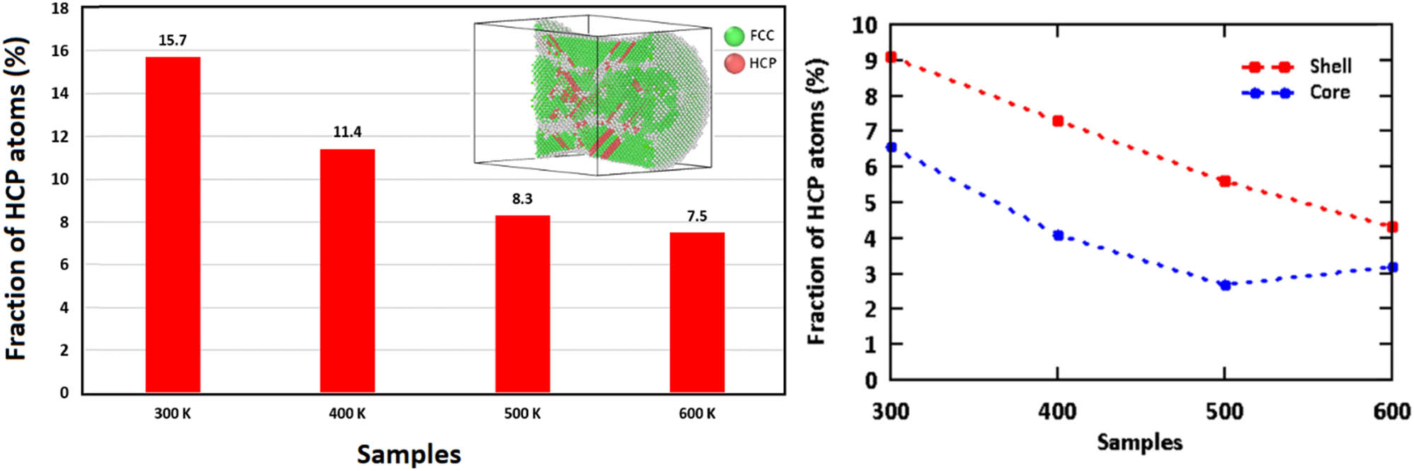
Fraction of the HCP atoms for the Cu–Au core–shell nanowire samples at the strain of 0.3.
4 Conclusion
This study carried out tensile tests by MD simulations to explore the effects of tension rate and temperature on the mechanical features and plastic deformation mechanisms of Cu–Au nanowires. In this study, it was found that Shockley partial dislocations nucleated upon yielding, leading to stacking fault formation. In fact, the stress concentration at the interface area reduces the energy barrier of dislocation nucleation. Consequently, it can be said that the interface region is a non-coherent area due to the atomic mismatch and represents a major site for the generation of crystallographic defects. It was observed that the reduction in the strain rate increased the dislocation density and stacking fault regions in light of sufficient time for nucleation. As a result, it can be said that dislocation nucleation is a time-dependent process. It was also demonstrated that temperature rising diminishes the energy barrier of dislocation nucleation due to the excitation of atoms by heat, substantially increasing the dislocation density and stacking fault areas. The quantitative analyses revealed that opposite-sign dislocations removed each other due to the recovery mechanisms once the temperature rose to 600 K, reducing the dislocation density.
In general, plastic deformation in nanostructures is attributed to the nucleation and slip of dislocations. The interaction between dislocations can result in locked dislocations that impede the plastic deformation process. However, with increasing temperature, thermal energy promotes the slip of dislocations. To better understand dislocation interactions, future designs should analyze the impact of core and shell thicknesses.
Acknowledgments
The authors would like to thank indeed Mustansiriyah University (http://www.uomustansiriyah.edu.iq) Baghdad, Iraq, for support the present work.
-
Author contributions: Ibrahim Abdulwahhab Atiyah: conceptualization, methodology, writing – original draft; Ismail Ibrahim Marhoon: investigation, resources, writing – review and editing; Raed Kadhim Mohammed Jawad: validation, writing and editing.
-
Conflict of interest: The authors declare that they have no conflict of interest.
-
Data availability statement: No data was used for the research described in this article.
References
[1] Niu Z, Chen S, Yu Y, Lei T, Dehestani A, Schierle-Arndt K, et al. Morphology-controlled transformation of Cu@Au core-shell nanowires into thermally stable Cu3Au intermetallic nanowires. Nano Res. 2020;13(9):2564–9.Suche in Google Scholar
[2] Na HG, Kwak DS, Kwon YJ, Cho HY, Lee C, Kim HW. TiO2/SiOx core-shell nanowires generated by heating the multilayered substrates. Met Mater Int. 2013;19(4):861–7.10.1007/s12540-013-4030-6Suche in Google Scholar
[3] Lee K, Seo J, Ahn J, Kwon H, Yang H. A simple route for the synthesis of copper nanowires. Met Mater Int. 2012;18(4):727–30.10.1007/s12540-012-4017-8Suche in Google Scholar
[4] Liu L, Hu S, Wang Y, Yang S, Qu J. Optimizing the Synthesis of Core/shell Structure Au@Cu2S Nanocrystals as Contrast-enhanced for Bioimaging Detection. Sci Rep. 2018;8(1):8866.10.1038/s41598-018-27015-xSuche in Google Scholar PubMed PubMed Central
[5] Stewart IE, Ye S, Chen Z, Flowers PF, Wiley BJ. Synthesis of Cu–Ag, Cu–Au, and Cu–Pt core–shell nanowires and their use in transparent conducting films. Chem Mater. 2015;27(22):7788–94.10.1021/acs.chemmater.5b03709Suche in Google Scholar
[6] Zhang H, Tian Y, Wang S, Feng J, Hang C, Wang C, et al. Robust Cu-Au alloy nanowires flexible transparent electrode for asymmetric electrochromic energy storage device. Chem Eng J. 2021;426:131438.10.1016/j.cej.2021.131438Suche in Google Scholar
[7] Trong DN. Factors affecting the depth of the Earth’s surface on the heterogeneous dynamics of Cu1−x Nix alloy, x = 0.1, 0.3, 0.5, 0.7, 0.9 by molecular dynamics simulation method. Mater Today Commun. 2021;29:102812.10.1016/j.mtcomm.2021.102812Suche in Google Scholar
[8] Trong DN, Long VC, Ţălu Ş. The influence of shape and matrix size on the mechanical properties of the 2D epoxy thin film by Monte Carlo simulation method. AIP Adv. 2023;13(1):015209.10.1063/5.0138329Suche in Google Scholar
[9] Yang Z, Li M, Li Y, Yang Y, Zhao J. Molecular dynamics simulation on torsion deformation of copper aluminum core–shell nanowires. J Nanopart Res. 2021;23(10):234.10.1007/s11051-021-05344-9Suche in Google Scholar
[10] Huang R, Shao G-F, Zeng X-M, Wen Y-H. Diverse melting modes and structural collapse of hollow bimetallic core-shell nanoparticles: A perspective from molecular dynamics simulations. Sci Rep. 2014;4(1):7051.10.1038/srep07051Suche in Google Scholar PubMed PubMed Central
[11] Zepeda-Ruiz LA, Stukowski A, Oppelstrup T, Bulatov VV. Probing the limits of metal plasticity with molecular dynamics simulations. Nature. 2017;550(7677):492–5.10.1038/nature23472Suche in Google Scholar PubMed
[12] Wolf D, Yamakov V, Phillpot S, Mukherjee A, Gleiter H. Deformation of nanocrystalline materials by molecular-dynamics simulation: relationship to experiments? Acta Mater. 2005;53(1):1–40.10.1016/j.actamat.2004.08.045Suche in Google Scholar
[13] Zeng L, Gao R, Fang Q, Wang X, Xie Z, Miao S, et al. High strength and thermal stability of bulk Cu/Ta nanolamellar multilayers fabricated by cross accumulative roll bonding. Acta Mater. 2016;110:341–51.10.1016/j.actamat.2016.03.034Suche in Google Scholar
[14] Samawi KA, Salman EA, Alshekhly BA, Nassar MF, Borzehandani MY, Abdulkareem-Alsultan G, et al. Rational design of different π-bridges and their theoretical impact on indolo [3, 2, 1-jk] carbazole based dye-sensitized solar cells. Comput Theor Chem. 2022 Jun;1212:113725.10.1016/j.comptc.2022.113725Suche in Google Scholar
[15] Weinberger CR, Tucker GJ. Multiscale materials modeling for nanomechanics; 2016. Cham, Switzerland: Springer; 2016.10.1007/978-3-319-33480-6Suche in Google Scholar
[16] Sarkar J, Das D. Molecular dynamics study of defect and dislocation behaviors during tensile deformation of copper-silver core-shell nanowires with varying core diameter and shell thickness. J Nanopart Res. 2018;20(10):272.10.1007/s11051-018-4386-0Suche in Google Scholar
[17] Santhapuram RR, Spearot DE, Nair AK. Mechanical behavior of core–shell nanostructures. J Mater Sci. 2020;55(10):4303–10.10.1007/s10853-019-04263-4Suche in Google Scholar
[18] Ke H, Mastorakos I. Deformation behavior of core–shell nanowire structures with coherent and semi-coherent interfaces. J Mater Res. 2019;34(7):1093–102.10.1557/jmr.2018.491Suche in Google Scholar
[19] El Jery A, Salman HM, Al-Khafaji RM, Nassar MF, Sillanpää M. Thermodynamics investigation and artificial neural network prediction of energy, exergy, and hydrogen production from a solar thermochemical plant using a polymer membrane electrolyzer. Molecules. 2023;28(6):2649.10.3390/molecules28062649Suche in Google Scholar PubMed PubMed Central
[20] Sarkar J. Investigation of mechanical properties and deformation behavior of single-crystal Al-Cu core-shell nanowire generated using non-equilibrium molecular dynamics simulation. J Nanopart Res. 2018;20(6):153.10.1007/s11051-018-4258-7Suche in Google Scholar
[21] Wang J, Shin S. Room temperature nanojoining of Cu-Ag core-shell nanoparticles and nanowires. J Nanopart Res. 2017;19(2):53.10.1007/s11051-017-3761-6Suche in Google Scholar
[22] Xue W, Yin H, Lu Z, Feng Y, Wang A, Liu S, et al. Catalytic oxidation of 1, 2-propanediol over bimetallic Cu@Au core/shell nanoparticles. Catal Lett. 2016;146(6):1139–52.10.1007/s10562-016-1736-3Suche in Google Scholar
[23] Yin F, Wang ZW, Palmer RE. Controlled formation of mass-selected Cu–Au core–shell cluster beams. J Am Chem Soc. 2011;133(27):10325–7.10.1021/ja201218nSuche in Google Scholar PubMed
[24] Trong DN, Long VC, Saraç U, Quoc VD, Ţălu Ş. First-principles calculations of crystallographic and electronic structural properties of Au-Cu alloys. J Compos Sci. 2022;6(12):383.10.3390/jcs6120383Suche in Google Scholar
[25] Niu Z, Cui F, Yu Y, Becknell N, Sun Y, Khanarian G, et al. Ultrathin epitaxial Cu@Au core–shell nanowires for stable transparent conductors. J Am Chem Soc. 2017;139(21):7348–54.10.1021/jacs.7b02884Suche in Google Scholar PubMed
[26] Niu Z, Chen S, Yu Y, Lei T, Dehestani A, Schierle-Arndt K, et al. Morphology-controlled transformation of Cu@Au core-shell nanowires into thermally stable Cu3Au intermetallic nanowires. Nano Res. 2020;13:2564–9.10.1007/s12274-020-2900-zSuche in Google Scholar
[27] Salman EA, Samawi KA, Nassar MF, Abdulkareem-Alsultan G, Abdulmalek E. 3D Hollow Spheres Comprising MXene/g-C3N4 Heterostructre for Efficient Polysulfide Adsorption and Conversion in High-Performance Li-S Batteries. J Electroanal Chem. 2023;945:117629.10.1016/j.jelechem.2023.117629Suche in Google Scholar
[28] Wu C-D, Jiang W-X. Molecular dynamics study on deformation and mechanics of nanoscale Au/Cu multilayers under indentation. J Mol Model. 2018;24:1–7.10.1007/s00894-018-3792-7Suche in Google Scholar PubMed
[29] Quoc TT, Long VC, Ţălu Ş, Nguyen Trong D. Molecular Dynamics Study on the Crystallization Process of Cubic Cu–Au Alloy. Appl Sci. 2022;12(3):946.10.3390/app12030946Suche in Google Scholar
[30] Li B, Amin AH, Ali AM, Isam M, Lagum AA, Sabugaa MM, et al. UV and solar-based photocatalytic degradation of organic pollutants from ceramics industrial wastewater by Fe-doped ZnS nanoparticles. Chemosphere. 2023;139208.10.1016/j.chemosphere.2023.139208Suche in Google Scholar PubMed
[31] Zhao L, Liu Y. The influence mechanism of the strain rate on the tensile behavior of copper nanowire. Sci China Technol Sci. 2019;62(11):2014–20.10.1007/s11431-019-9530-6Suche in Google Scholar
[32] Catenacci MJ, Reyes C, Cruz MA, Wiley BJ. Stretchable conductive composites from Cu–Ag nanowire felt. ACS Nano. 2018;12(4):3689–98.10.1021/acsnano.8b00887Suche in Google Scholar PubMed
[33] Kim D, Bang J, Won P, Kim Y, Jung J, Lee J, et al. Biocompatible cost‐effective electrophysiological monitoring with oxidation‐free Cu–Au Core–shell nanowire. Adv Mater Technol. 2020;5(12):2000661.10.1002/admt.202000661Suche in Google Scholar
[34] Liverani E, Rogati G, Pagani S, Brogini S, Fortunato A, Caravaggi P. Mechanical interaction between additive-manufactured metal lattice structures and bone in compression: implications for stress shielding of orthopaedic implants. J Mech Behav Biomed Mater. 2021;121:104608.10.1016/j.jmbbm.2021.104608Suche in Google Scholar PubMed
[35] Saed kariem Alawamleh H, Amin AH, Ali AM, Abd Alreda B, Lagum AA, Pecho RD, et al. Solar light driven enhanced photocatalytic treatment of azo dye contaminated water based on Co-doped ZnO/g-C3N4 nanocomposite. Chemosphere. 2023;335:139104.10.1016/j.chemosphere.2023.139104Suche in Google Scholar PubMed
[36] Nguyen-Trong D. Z-AXIS deformation method to investigate the influence of system size, structure phase transition on mechanical properties of bulk nickel. Mater Chem Phys. 2020;252:123275.10.1016/j.matchemphys.2020.123275Suche in Google Scholar
[37] Luan S, Tang B, Zhao Q, Wan H, Yu S, Gui C, et al. Length effects on tensile behavior of Au-Ag heterostructured nanowires with the load on different ends: A molecular dynamics study. Phys Lett A. 2020;384(36):126929.10.1016/j.physleta.2020.126929Suche in Google Scholar
[38] Alsultan AG, Asikin-Mijan N, Obeas LK, Islam A, Mansir N, Teo SH, et al. Selective deoxygenation of sludge palm oil into diesel range fuel over Mn-Mo supported on activated carbon catalyst. Catalysts. 2022;12(5):566.10.3390/catal12050566Suche in Google Scholar
[39] Gola A, Pastewka L. Embedded atom method potential for studying mechanical properties of binary Cu–Au alloys. Model Simul Mater Sci Eng. 2018;26(5):055006.10.1088/1361-651X/aabce4Suche in Google Scholar
[40] Kart HH, Tomak M, Çağin T. Thermal and mechanical properties of Cu–Au intermetallic alloys. Model Simul Mater Sci Eng. 2005;13(5):657.10.1088/0965-0393/13/5/002Suche in Google Scholar
[41] Chen D-L, Chen T-C. Mechanical properties of Au nanowires under uniaxial tension with high strain-rate by molecular dynamics. Nanotechnology. 2005;16(12):2972.10.1088/0957-4484/16/12/041Suche in Google Scholar
[42] Allen MP, Tildesley DJ. Computer simulation of liquids. Oxford, UK: Oxford University Press; 2017.10.1093/oso/9780198803195.001.0001Suche in Google Scholar
[43] Stukowski A, Albe K. Extracting dislocations and non-dislocation crystal defects from atomistic simulation data. Model Simul Mater Sci Eng. 2010;18:085001.10.1088/0965-0393/18/8/085001Suche in Google Scholar
[44] Tsuzuki H, Branicio PS, Rino JP. Structural characterization of deformed crystals by analysis of common atomic neighborhood. Comput Phys Commun. 2007;177(6):518–23.10.1016/j.cpc.2007.05.018Suche in Google Scholar
[45] Li J, Lu B, Zhou H, Tian C, Xian Y, Hu G, et al. Molecular dynamics simulation of mechanical properties of nanocrystalline platinum: Grain-size and temperature effects. Phys Lett A. 2019;383(16):1922–8.10.1016/j.physleta.2018.10.053Suche in Google Scholar
[46] Zhan H, Gu Y, Yan C, Feng X-Q, Yarlagadda P. Numerical exploration of plastic deformation mechanisms of copper nanowires with surface defects. Comput Mater Sci. 2011;50(12):3425–30.10.1016/j.commatsci.2011.07.004Suche in Google Scholar
[47] Deng C, Sansoz F. Fundamental differences in the plasticity of periodically twinned nanowires in Au, Ag, Al, Cu, Pb and Ni. Acta Mater. 2009;57(20):6090–101.10.1016/j.actamat.2009.08.035Suche in Google Scholar
[48] Sun C, Guo N, Fu M, Wang S. Modeling of slip, twinning and transformation induced plastic deformation for TWIP steel based on crystal plasticity. Int J Plast. 2016;76:186–212.10.1016/j.ijplas.2015.08.003Suche in Google Scholar
[49] Liao X, Zhao Y, Srinivasan S, Zhu Y, Valiev R, Gunderov D. Deformation twinning in nanocrystalline copper at room temperature and low strain rate. Appl Phys Lett. 2004;84(4):592–4.10.1063/1.1644051Suche in Google Scholar
[50] Rohith P, Sainath G, Srinivasan V. Effect of size, temperature and strain rate on dislocation density and deformation mechanisms in Cu nanowires. Phys B: Condens Matter. 2019;561:136–40.10.1016/j.physb.2019.03.003Suche in Google Scholar
[51] Veerababu J, Manzoor U, Sainath G, Goyal S, Sandhya R. Deformation behavior of Cu nanowire with axial stacking fault. Mater Res Express. 2019;6(7):075056.10.1088/2053-1591/ab17c1Suche in Google Scholar
[52] Cao G, Wang J, Du K, Wang X, Li J, Zhang Z, et al. Superplasticity in gold nanowires through the operation of multiple slip systems. Adv Funct Mater. 2018;28(51):1805258.10.1002/adfm.201805258Suche in Google Scholar
[53] Tian X, Yang H, Cui J, Yu X, Wan R. Deformation mechanisms of Cu nanowires with planar defects. J Appl Phys. 2015;117(3):034309.10.1063/1.4906278Suche in Google Scholar
[54] Hou Z, Li C, Liu L, Gao Q, Wang J, Liu R, et al. Three-dimensional topological structures and formation processes of dislocations in Au nanowire under tension loading. Comput Mater Sci. 2021;197:110639.10.1016/j.commatsci.2021.110639Suche in Google Scholar
[55] Jiang S, Jiang Z, Chen Q. Deformation twinning mechanism in hexagonal-close-packed crystals. Sci Rep. 2019;9(1):618.10.1038/s41598-018-37067-8Suche in Google Scholar PubMed PubMed Central
[56] Sainath G, Goyal S, Nagesha A. Plasticity through de-twinning in twinned BCC nanowires. Crystals. 2020;10(5):366.10.3390/cryst10050366Suche in Google Scholar
[57] Sainath G, Choudhary B. Twinning to slip transition in ultrathin BCC Fe nanowires. Phys Lett A. 2018;382(15):1047–51.10.1016/j.physleta.2018.02.007Suche in Google Scholar
[58] Eftink BP, Li A, Szlufarska I, Mara NA, Robertson IM. Deformation response of AgCu interfaces investigated by in situ and ex situ TEM straining and MD simulations. Acta Mater. 2017;138:212–23.10.1016/j.actamat.2017.07.051Suche in Google Scholar
[59] Amigo N, Gutiérrez G, Ignat M. Atomistic simulation of single crystal copper nanowires under tensile stress: Influence of silver impurities in the emission of dislocations. Comput Mater Sci. 2014;87:76–82.10.1016/j.commatsci.2014.02.014Suche in Google Scholar
[60] Su M, Deng Q, An M, Liu L, Ma C. Molecular dynamics study of the tensile behaviors of Ti (0 0 0 1)/Ni (1 1 1) multilayered nanowires. Comput Mater Sci. 2019;158:149–58.10.1016/j.commatsci.2018.11.019Suche in Google Scholar
[61] Fan H, Wang Q, El-Awady JA, Raabe D, Zaiser M. Strain rate dependency of dislocation plasticity. Nat Commun. 2021;12:1845.10.1038/s41467-021-21939-1Suche in Google Scholar PubMed PubMed Central
[62] Sun H, Kumar A, Singh CV. Deformation behavior of BCC tantalum nanolayered composites with modulated layer thicknesses. Mater Sci Eng A. 2019;761:138037.10.1016/j.msea.2019.138037Suche in Google Scholar
[63] Sankaranarayanan SK, Bhethanabotla VR, Joseph B. Molecular dynamics simulation of temperature and strain rate effects on the elastic properties of bimetallic Pd-Pt nanowires. Phys Rev B. 2007;76(13):134117.10.1103/PhysRevB.76.134117Suche in Google Scholar
[64] Mishra DK, Meraj M, BadJena SK, Pal S. Dislocation interaction and V-shaped growth of the distorted structure during nanoindentation of Cu20Ni20Al20Co20Fe20 (high-entropy alloy)-coated copper: A molecular dynamics simulation-based study. Trans Indian Inst Met. 2019;72(1):167–80.10.1007/s12666-018-1471-0Suche in Google Scholar
[65] Porter DA, Easterling KE, Sherif MY. Phase transformations in metals and alloys. 3rd ed. Boca Raton (FL), USA: CRC Press; 2009.10.1201/9781439883570Suche in Google Scholar
[66] Nasiri S, Zaiser M. Effects of elasticity and dislocation core structure on the interaction of dislocations with embedded CNTs in aluminium: An atomistic simulation study. Materialia. 2022;21:101347.10.1016/j.mtla.2022.101347Suche in Google Scholar
[67] Yamakov V, Wolf D, Phillpot S, Gleiter H. Dislocation–dislocation and dislocation–twin reactions in nanocrystalline Al by molecular dynamics simulation. Acta Mater. 2003;51(14):4135–47.10.1016/S1359-6454(03)00232-5Suche in Google Scholar
[68] Zhang L, Shibuta Y. Inverse Hall-Petch relationship of high-entropy alloy by atomistic simulation. Mater Lett. 2020;274:128024.10.1016/j.matlet.2020.128024Suche in Google Scholar
[69] Wang L, Zhang Z, Ma E, Han X. Transmission electron microscopy observations of dislocation annihilation and storage in nanograins. Appl Phys Lett. 2011;98(5):051905.10.1063/1.3549866Suche in Google Scholar
© 2023 the author(s), published by De Gruyter
This work is licensed under the Creative Commons Attribution 4.0 International License.
Artikel in diesem Heft
- Research Articles
- The mechanical properties of lightweight (volcanic pumice) concrete containing fibers with exposure to high temperatures
- Experimental investigation on the influence of partially stabilised nano-ZrO2 on the properties of prepared clay-based refractory mortar
- Investigation of cycloaliphatic amine-cured bisphenol-A epoxy resin under quenching treatment and the effect on its carbon fiber composite lamination strength
- Influence on compressive and tensile strength properties of fiber-reinforced concrete using polypropylene, jute, and coir fiber
- Estimation of uniaxial compressive and indirect tensile strengths of intact rock from Schmidt hammer rebound number
- Effect of calcined diatomaceous earth, polypropylene fiber, and glass fiber on the mechanical properties of ultra-high-performance fiber-reinforced concrete
- Analysis of the tensile and bending strengths of the joints of “Gigantochloa apus” bamboo composite laminated boards with epoxy resin matrix
- Performance analysis of subgrade in asphaltic rail track design and Indonesia’s existing ballasted track
- Utilization of hybrid fibers in different types of concrete and their activity
- Validated three-dimensional finite element modeling for static behavior of RC tapered columns
- Mechanical properties and durability of ultra-high-performance concrete with calcined diatomaceous earth as cement replacement
- Characterization of rutting resistance of warm-modified asphalt mixtures tested in a dynamic shear rheometer
- Microstructural characteristics and mechanical properties of rotary friction-welded dissimilar AISI 431 steel/AISI 1018 steel joints
- Wear performance analysis of B4C and graphene particles reinforced Al–Cu alloy based composites using Taguchi method
- Connective and magnetic effects in a curved wavy channel with nanoparticles under different waveforms
- Development of AHP-embedded Deng’s hybrid MCDM model in micro-EDM using carbon-coated electrode
- Characterization of wear and fatigue behavior of aluminum piston alloy using alumina nanoparticles
- Evaluation of mechanical properties of fiber-reinforced syntactic foam thermoset composites: A robust artificial intelligence modeling approach for improved accuracy with little datasets
- Assessment of the beam configuration effects on designed beam–column connection structures using FE methodology based on experimental benchmarking
- Influence of graphene coating in electrical discharge machining with an aluminum electrode
- A novel fiberglass-reinforced polyurethane elastomer as the core sandwich material of the ship–plate system
- Seismic monitoring of strength in stabilized foundations by P-wave reflection and downhole geophysical logging for drill borehole core
- Blood flow analysis in narrow channel with activation energy and nonlinear thermal radiation
- Investigation of machining characterization of solar material on WEDM process through response surface methodology
- High-temperature oxidation and hot corrosion behavior of the Inconel 738LC coating with and without Al2O3-CNTs
- Influence of flexoelectric effect on the bending rigidity of a Timoshenko graphene-reinforced nanorod
- An analysis of longitudinal residual stresses in EN AW-5083 alloy strips as a function of cold-rolling process parameters
- Assessment of the OTEC cold water pipe design under bending loading: A benchmarking and parametric study using finite element approach
- A theoretical study of mechanical source in a hygrothermoelastic medium with an overlying non-viscous fluid
- An atomistic study on the strain rate and temperature dependences of the plastic deformation Cu–Au core–shell nanowires: On the role of dislocations
- Effect of lightweight expanded clay aggregate as partial replacement of coarse aggregate on the mechanical properties of fire-exposed concrete
- Utilization of nanoparticles and waste materials in cement mortars
- Investigation of the ability of steel plate shear walls against designed cyclic loadings: Benchmarking and parametric study
- Effect of truck and train loading on permanent deformation and fatigue cracking behavior of asphalt concrete in flexible pavement highway and asphaltic overlayment track
- The impact of zirconia nanoparticles on the mechanical characteristics of 7075 aluminum alloy
- Investigation of the performance of integrated intelligent models to predict the roughness of Ti6Al4V end-milled surface with uncoated cutting tool
- Low-temperature relaxation of various samarium phosphate glasses
- Disposal of demolished waste as partial fine aggregate replacement in roller-compacted concrete
- Review Articles
- Assessment of eggshell-based material as a green-composite filler: Project milestones and future potential as an engineering material
- Effect of post-processing treatments on mechanical performance of cold spray coating – an overview
- Internal curing of ultra-high-performance concrete: A comprehensive overview
- Special Issue: Sustainability and Development in Civil Engineering - Part II
- Behavior of circular skirted footing on gypseous soil subjected to water infiltration
- Numerical analysis of slopes treated by nano-materials
- Soil–water characteristic curve of unsaturated collapsible soils
- A new sand raining technique to reconstitute large sand specimens
- Groundwater flow modeling and hydraulic assessment of Al-Ruhbah region, Iraq
- Proposing an inflatable rubber dam on the Tidal Shatt Al-Arab River, Southern Iraq
- Sustainable high-strength lightweight concrete with pumice stone and sugar molasses
- Transient response and performance of prestressed concrete deep T-beams with large web openings under impact loading
- Shear transfer strength estimation of concrete elements using generalized artificial neural network models
- Simulation and assessment of water supply network for specified districts at Najaf Governorate
- Comparison between cement and chemically improved sandy soil by column models using low-pressure injection laboratory setup
- Alteration of physicochemical properties of tap water passing through different intensities of magnetic field
- Numerical analysis of reinforced concrete beams subjected to impact loads
- The peristaltic flow for Carreau fluid through an elastic channel
- Efficiency of CFRP torsional strengthening technique for L-shaped spandrel reinforced concrete beams
- Numerical modeling of connected piled raft foundation under seismic loading in layered soils
- Predicting the performance of retaining structure under seismic loads by PLAXIS software
- Effect of surcharge load location on the behavior of cantilever retaining wall
- Shear strength behavior of organic soils treated with fly ash and fly ash-based geopolymer
- Dynamic response of a two-story steel structure subjected to earthquake excitation by using deterministic and nondeterministic approaches
- Nonlinear-finite-element analysis of reactive powder concrete columns subjected to eccentric compressive load
- An experimental study of the effect of lateral static load on cyclic response of pile group in sandy soil