Numerical modeling of connected piled raft foundation under seismic loading in layered soils
-
Ahmed M. Ali
 und
Ala N. Al-Jorany
und
Ala N. Al-Jorany

Abstract
Until recently, the behavior of connected piled raft foundation was not fully understood in the seismically active region due to the complex dynamic soil–pile–foundation structure interaction. This concern arises when the soil deposit-supported foundations are stratified or heterogynous and subjected to high ground motion intensity. In the current study, a series of numerical analyses using ABAQUS software have been conducted on a pile group of (3 × 3) arranged into a square pattern to investigate the seismic response of piled foundations embedded in dry sandy soil (homogenous and layered), and how the amplification of propagated waves affects the bending moment along piles. For mesh generation, an artificial boundary condition using the tied-nodes approach was adopted to simulate the free-field motion of soil under earthquake excitation. The structure used a single degree of freedom with a lumped mass. Moreover, Mohr–Coulomb and linear elastic models have been chosen for soil and pile–raft, respectively. The results demonstrate that the foundation rocking increases in stratified soil compared to homogenous soil, irrespective of the seismic intensity. The maximum bending moment was observed at the pile head in homogenous soil and shallow depths in layered soil because of the kinematic interaction at the soil interface. The results also indicated that the amplification factor (acceleration at a certain depth to the acceleration at bedrock) was found to be 203 and 189% in homogenous soil for PGA values of 0.1 and 0.33 g, respectively. Almost there were no effects of seismic intensity in layered soil on the amplified waves transmitted into the soil surface.
1 Introduction
The dynamic response of piled raft foundation has recently received noticeable attention in the literature [1]. The complexity of seismic response involves determining the inertial and kinematic interactions between the soil and the piles and how the soil nonlinearly responds to strong seismic intensity. Although these topics revealed that the piled raft foundations perform well in generally firm soils, the problems arise for piles installed in layered soil or these susceptible to liquefaction or ground amplification. Consequently, the piled foundation placed on relatively soft soil may be exposed to amplified loading even for small ground motion [2,3]. The seismic soil–pile structure interaction (SSPS) can be deleterious or beneficial based on many factors, such as structure characteristics, earthquake intensity, and soil type. The SSPS resorts to increasing the damping and the fundamental period of the system, and thus, the foundation-supported structure may be vulnerable even to moderate earthquakes. Although the SSPS, according to NEHRP, is traditionally beneficial and thus may be neglected, recent seismic building codes, such as Eurocode8 (2004), accounted for the inertial and kinematic mechanism in pile design. A connected piled raft foundation (CPRF) can utilize the raft and the piles to transfer the external loads into the subsoil. Its applications have been excessively accepted to reduce differential settlement issues and improve the foundation performance, and numerous reports have confirmed their satisfying behavior [4,5].
Banerjee et al. [6] investigated the seismic response of connected piles placed in the soft soil using numerical and experimental models. The earthquake-induced bending moment of piles has been explored. Kumar et al. [7] also observed that the maximum bending moment was at the pile head due to its connection to the raft, and all crossover points were found at shallow depths of the pile. Garala and Madabhushi [8] studied the effect of SSPS on a single pile embedded in stratified soil and stated that the bending moment in piles due to inertial interaction prevailed at strong ground motion compared to the kinematic interaction. The importance of kinematic loads appears at small base excitation.
This study is devoted to extending the physical models carried out under the effect of unidirectional horizontal shaking. The test results of the shaking table rely on the response of the geo-material and structure models in the lateral direction, albeit there have been researches indicating the influence of the vertical components in addition to the pulse-like motion during the strong seismic records as stated by Davoodi et al. [9] and Mazza et al. [10]. Zhu et al. [11] pointed out the effect of horizontal pulse-like motion and its vertical component on the seismic response of sloped soil profile. It was found that a direct relationship between the amplification factor in the horizontal direction (AAF) and the soil height. However, the vertical AAF has no salient effect on the elevation amplification. When the horizontal pulse-like motion is used, the influence of the vertical component on the horizontal amplification factor is limited, and hence, the vertical seismic response is highly promoted by the horizontal component.
The present study aims to investigate the seismic response of connected piled raft foundations and how this system behaves in homogenous and stratified soil during a set of ground motion intensities using numerical approaches. A total of six numerical models using finite element software ABAQUS have been performed on piled foundations to investigate the effect of earthquake excitation on its seismic response. A group of piles in (3 × 3) squared pattern was used. Two ground motion signals in terms of time history have been chosen. El Centro earthquake record (1979) has been modified to cover a rational range of intensities, including PGA values of 0.1 and 0.33 g with a total period of 10 s, where PGA is the peak ground acceleration of the signal. The CPRF was installed in two states of soil, homogenous soil with a relative density (RD = 50%) and layered soil, which includes a layer of very loose (RD = 20%) sand in different depths overlaid by the homogenous sand. The thickness of the very loose sand is taken as a percent of the pile length (one-third and two-thirds). Furthermore, time histories through soil layers, raft and structure, and the bending moment along piles have been extensively analyzed. By surveying the topography of most of the regions in Iraq, the laboratory and in situ tests exhibited a sedimentary nature of the soil profiles, primarily for the depths near the ground surface. Such types of soils have a great tendency to amplify or liquefy upon seismic activities. Thus, the study contributes more insight into the pile raft foundation model’s seismic response on such inconsistent layers. The layered soil can produce combined loads on the pile due to the ease of its free field motion and the inertia forces imposed by the structure during the earthquake.
2 Overview of the case history and problem statement
Concerning simulation of the nine-story building of 28 m in height, it was placed on sandy soil and compensated with a single degree of freedom system SDOF, which comprises a lumped mass for the total weight of the structure. It is connected to a solid slender to represent the stiffness of the structure. Modal analysis was performed on the prototype structure to extract the dynamic response using Matlab software. By knowing the mass of each story and its corresponding stiffness (fixed-fixed connection for the columns), the natural period was found to equal 0.98 s. The scale factor used in this study is 50. This value considered the modeling’s geometric, kinematic, and dynamic aspects. Thus, the details of SDOF are 8.8 kg and 35 cm for the lumped mass and structure height, respectively, which directly represent the mass and height of the structure.
A rigid foundation model slab is 20 cm × 20 cm and 1.5 cm thick and is made of aluminum. Hollow aluminum piles were used with a length of 45 and 2.2 cm in outer diameter. The piles are fixedly connected to the raft and arranged in a square pattern three times the pile diameter apart center to center. The soil model used in this study has dimensions of 80 m × 60 m × 85 m in length, width, and depth, respectively. Full details on the CPRF scheme are shown in Figure 1.
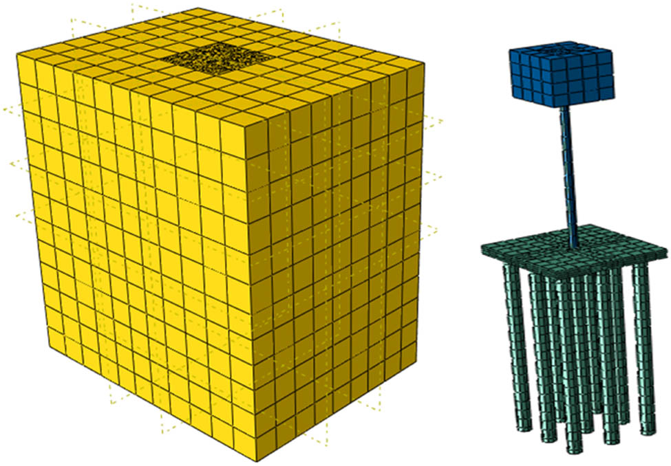
Schematic representation for the soil, piled foundation, and the structure model.
Medium and loose sand has been used for the homogenous and layered soil, respectively. Characterization of pile, raft, and structure is listed in Table 1. The shear wave velocity is a major key for obtaining the theoretical natural frequency of the soil. Due to the absence of a bender element sensor in this analysis, a validated statistical equation proposed by El-Sekelly et al. [12] was adopted to measure the shear velocity through the soil layers and can be formulated as follows:
where v s is the shear wave velocity of the soil, e is a void ratio, and σ 0 is confining stress of the soil.
Summary of the characteristics of the pile, raft, and structure adopted
| Property index | Notation | Value | Material |
|---|---|---|---|
| Raft dimensions (cm) | B | 20 | Aluminum |
| Floor thickness (cm) | t | 1.5 | |
| Pile length (cm) | L p | 45 | |
| Outer diameter (cm) | D O | 2.3 | |
| Inner diameter (cm) | D 1 | 2 | |
| Young Modulus (kPa) | E a | 67 × 106 | |
| Mass Density (kg/m3) | ρ a | 2,700 | |
| Lumped mass (kg) | M | 8.8 | Steel |
| Height of SDOF (cm) | h | 35 | |
| Young Modulus (kPa) | E s | 200 × 106 | |
| Mass Density (kg/m3) | ρ s | 7,800 |
3 Process of numerical modeling
The elastic perfectly plastic (Mohr–Coulomb) model was used for the soil due to its simplicity and the feasible representation of the plastic strain generated during the strong earthquake. The input parameters used in the numerical analysis for the elastic–perfectly plastic model are illustrated in Table 2. A linear elastic model was adopted for the piles, raft, and structure. The modeling of soil medium was performed using C3D8R continuum element (3D, brick-8nodes, reduced integration, and hourglass control). As shown in Figure 2, the integration points are located in the middle of the element. Thus, fine mesh is needed to hold the concentration of stresses at the soil boundaries.
ABAQUS input parameters used in the current study for the soil model
| Parameter | Notation | Value | |
|---|---|---|---|
| Relative density (%) | RD | 50 | 20 |
| Modulus of elasticity (kPa) | Es | 33,000 | 24,000 |
| Poisson’s ratio | ν | 0.3 | 0.31 |
| Angle of internal friction (degree) | φ | 35 | 30 |
| Cohesion (kPa) | C | 6 | 2 |
| Dilation angle (degree) | ψ | 5 | 0 |
| Mass density (kg/m3) | ρ | 1,500 | 1,380 |
![Figure 2
Characterization of the 3D solid element used for the soil (after Van Nguyen et al. [13]).](/document/doi/10.1515/jmbm-2022-0250/asset/graphic/j_jmbm-2022-0250_fig_002.jpg)
Characterization of the 3D solid element used for the soil (after Van Nguyen et al. [13]).
The variation in the energy losses in soil was simulated using Rayleigh damping. The dissipation of energy is governed by the friction of the soil particles, which tries to reduce the wave amplitude and may alter the dynamic characteristics of the soil. Therefore, frequency analysis using ABAQUS has been conducted, and the coefficients of Rayleigh damping were extracted to be α = 1.54 and β = 0.00035 by taking the first and second modes of the natural frequencies at a damping ratio of 3%.
4 Boundary conditions and soil–pile interaction
In the topic of seismic–pile–soil interaction, the soil domain should be sufficient to minimize the wave reflection to the region of interest. So, many artificial adsorbing boundaries have been suggested to simulate energy dissipation during the numerical models. The adsorbing boundary available in ABAQUS is the infinite element boundary which requires the linear elastic behavior to perform well. This type may afford vulnerable results at the strong ground motion, where the plastic yielding is significantly developed. In this study, the principles of the tied-nodes method were adopted by connecting the collocated nodes on the vertical planes of the mesh domain perpendicular to the shaking direction, as depicted in Figure 3.

Plot representation for the tied nodes approach used at soil boundaries.
The corresponding nodes at the same level are constrained by the same degree of freedom to satisfy the movement in the direction of the earthquake. Such a method has been used by references [14,15] and others. This approach is well replicating the motion of the laminar shear box under 1 g-model tests. Due to the inequality conditions that lead to the interrupted stiffness in the tangential and normal direction, the difference in the contact definition can be the reason for the serious nonlinearities in the numerical simulation. The master-slave method was adopted to simulate the interaction between soil–raft and the piles. The more stiffness elements undertake the master option, and the nodes at the soil interface can be considered slave points. Surface-to-surface contact was used with the complex interaction and a large number of the contacted surfaces. For piles, the tangential behavior was chosen for the circumferential surfaces, and normal behavior with hard contact was adopted for the pile tip. The contact surface between the piles and the soil has been defined by the plenty method, and a friction coefficient between 0.12 and 1 should be included [16,17,18].
Based on the classical Mohr–Coulomb theory, 0.67 of the friction angle has been used in the present study. To obtain accurate results without affecting the computation time of the analysis, the size of mesh element should be related to the maximum frequency of the excitation and shear wave velocity. The widely accepted range of size of mesh element proposed by Ichimura et al. [19] is should be about 1/10 of the wavelength.
5 Results of numerical analysis
Two real-time histories of PGA = 0.1 and 0.33 g with a constant predominant frequency of 8.3 Hz have been used. These forcing functions are applied at the bedrock or the base of the soil domain. Spectrum acceleration and frequency domain was obtained using fast Fourier transform (FFT) to extract the frequency of interest, as illustrated in Figures 4 and 5. The selection of the ground motion as a seismic input has met the requirements of the earthquake activity, which are the amplitude, duration, and spectrum (frequency) characteristics [20]. The amplitude of the real seismic input is 0.35 g, and it was selected to represent the average ground motions that have been recorded in Iraq in the last decade. According to Iraqi meteorological seismology, the maximum amplitude of the seismic data, characterized by the acceleration, was registered in a range of 0.1–0.47 g. The influence of the frequency content was also accounted for in the selection process of earthquake records, where the value of the predominant frequency of the ground motion obtained by FFT is close enough to the fundamental frequency of the structure model (7.8 Hz).

Adopted earthquake motion used in this study at PGA = 0.33 and 0.1 g.

Frequency domain and spectrum acceleration for the two-time histories used in the present study.
5.1 Rocking of piled foundation during earthquake
Figure 6 shows the effect of foundation rocking at different ground motion intensities and for three cases of soil stratification. The homogenous sand is a layer of loose sand in a depth of 15 cm overlaid by homogenous sand (S1) and a layer of loose sand in a depth of 30 cm overlaid by homogenous sand (S2). The results revealed that the inertial forces generated compression on one side and uplifting on the other. The maximum rocking was noted in the case of S2 due to the ability of the foundation to settle more than in the case of homogenous soil. In the latter condition, the side friction of piles is higher than in the case of stratified soil S2.

Plot illustration of the rocking foundation with time.
Moreover, the soil-supported structure is more rigid and thus would be less susceptible to vertical displacement and rocking. In terms of seismic intensity, the less ground motion intensity is, the less rocking to develop because the kinematic-induced motion is more dominant than the inertial forces imposed on the piles. Hence, the rocking will be more influenced by the passage of soil motion.
5.2 Bending moment of pile models
The bending moment curves in Figure 7 are presented and compared for the cases of ground motion (PGA = 0.33 and 0.1 g). As suggested by Nguyen et al. [13], the bending moment was computed at the time in which the pile toe moves laterally and reaches a maximum value. As expected, the corner pile carries more of the imposed loads because of the shadow effect. Due to the symmetry condition of pile arrangement, three piles are to be considered in the analysis, which is located at the corner, edge, and center of the foundation, as depicted in Figure 8. The results demonstrated that the maximum bending moment occurs at the pile head when the piles are installed in homogenous and stratified soil (S1). It was noticeably found that the pile in the center is not affected by the intensity of earthquake records except in the case of stratified soil (S2). Irrespective of the pile position below the raft, and for the case of PGA = 0.33 g, the piles are subjected to a larger bending moment as compared to the piles tested in the case of PGA = 0.1 g.

Bending moment curves for different ground motion and soil stratification.

Configuration of piles within the raft foundations.
In homogenous sand, there is no substantial effect of the weak ground motion on the position of piles, where all the piles are approximately exposed to 2.65 N m. The corner pile has a slight preference for the edge pile in the bending moment in the case of PGA = 0.33 g. It can be noted that, for the stratified soils (S1 and S2), the edge and center piles have the same potential to carry the load applied by the superstructure for different earthquake intensities. This may be attributed to the fact that these piles are located at the neutral axis of the raft throughout the shaking (group effect). For the case of S2, the bending moment along piles is less than in the case of S1, although the rocking is more pronounced in case S2. The inertial forces transmitted to the piles would be less in the case of S2 due to the relatively large distance of the loose sand layer, which in turn leads to rearrangement of the particles during the base excitation. Thus, the kinematic forces will be predominant in this case. Also, the energy absorbed by the piles is small due to the reduction of shaft resistance along with the pile, leading to less oscillation of the structure. Little values of the bending moment were recorded at the toe because there is some movement of the soil assigned at the boundary condition along the line of pile toe.
The pattern of bending moment distribution along the pile models was validated by the findings obtained by Van Nguyen et al. [13]. The validation process was not accounted for reanalysis of the numerical tests performed by the author above due to some reasons. Both studies used the same finite element analysis software and employed different scale dimensions. The comparison would not be valid unless some similitude laws are rationally applied. The slenderness ratio (L p/D o) for the pile model (20.5) and the prototype (20.8) is nearly identical. After applying the scaling laws to obtain the flexural stiffness of the pile (EI), it seems that the pile model reflects the rigidity of the prototype. The validation procedure is performed to understand how much the pile model can replicate the trend of the actual piles to estimate the bending moment with depth. For this, the case of the pile model installed into a homogenous soil and subjected to a ground motion of 0.33 g has been compared to the case of the pile of 25 m long and excited by a seismic wave of 0.349 g. The results to be validated are illustrated in Figure 9. It is drawn that how the bending moment varies with depth approximately resembles the behavior of the pile model, where the maximum value of the moment was recorded at about one-fifth of the pile length. This finding could indicate the reliable results for the numerical analysis performed in the current study.
![Figure 9
Bending moment curves for the current and validated study (after Van Nguyen et al. [13]).](/document/doi/10.1515/jmbm-2022-0250/asset/graphic/j_jmbm-2022-0250_fig_009.jpg)
Bending moment curves for the current and validated study (after Van Nguyen et al. [13]).
6 Conclusions
Based on the numerical analysis performed in the present study, the following points can be drawn:
Inertial interaction in CPRF is dominant when the peak ground acceleration of 0.33 g is used.
The pile at the center of the raft does not affect by the intensity of ground motion, and it can carry the same applied load in homogenous soil.
The rocking of the foundation increases in stratified soil, and as the earthquake, ground motion increases.
The waves propagated at the soil surfaces are significantly amplified in stratified soil compared to homogenous sand.
The dynamic response of the structure in terms of PGA is larger than the soil and raft at all the values of earthquake intensities due to the inertial forces that increase the oscillation of the superstructure.
-
Funding information: The authors state no funding involved.
-
Author contributions: All authors have accepted responsibility for the entire content of this manuscript and approved its submission.
-
Conflict of interest: The authors state no conflict of interest.
References
[1] Iida M. Three-dimensional finite-element method for soil-building interaction based on an input wave field. Int J Geomech. 2013 Aug 1;13(4):430–40.Suche in Google Scholar
[2] Zhang L, Goh SH, Liu H. Seismic response of pile-raft-clay system subjected to a long-duration earthquake: centrifuge test and finite element analysis. Soil Dyn Earthq Eng. 2017 Jan 1;92:488–502.Suche in Google Scholar
[3] Karkush MO, Mohsin AH, Saleh HM, Noman BJ. Numerical Analysis of Piles Group Surrounded by Grouting Under Seismic Load. Geotechnical Engineering and Sustainable Construction. Singapore: Springer; 2022. p. 379–89.Suche in Google Scholar
[4] Yamashita K, Yamada T, Hamada J. Investigation of settlement and load sharing on piled rafts by monitoring full-scale structures. Soils Found. 2011;51(3):513–32.Suche in Google Scholar
[5] Karkush MO, Aljorany AN. Analytical and numerical analysis of piled-raft foundation of storage tank. In Construction. Geotechnical Engineering. Singapore: Springer; 2020. p. 373–84.Suche in Google Scholar
[6] Banerjee S, Goh SH, Lee FH. Earthquake-induced bending moment in fixed-head piles in soft clay. Géotechnique. 2014 May;64(6):431–46.Suche in Google Scholar
[7] Kumar A, Choudhury D, Shukla J, Shah DL. Seismic design of pile foundation for oil tank by using PLAXIS3D. Disaster Adv. 2015;8(6):33–42.Suche in Google Scholar
[8] Garala TK, Madabhushi SP. Kinematic and inertial seismic load effects on pile foundations in stratified soil. Earthquake Geotechnical Engineering for Protection and Development of Environment and Constructions. Boca Raton (FL): CRC Press; 2019 Oct 22. p. 2534–41.Suche in Google Scholar
[9] Davoodi M, Jafari MK, Hadiani N. Seismic response of embankment dams under near-fault and far-field ground motion excitation. Eng Geol. 2013;158:66–76.Suche in Google Scholar
[10] Mazza F, Mazza M, Vulcano A. Nonlinear response of rc framed buildings retrofitted by different base-isolation systems under horizontal and vertical components of near-fault earthquakes. Earthq Struct. 2017;12(1):135–44.Suche in Google Scholar
[11] Zhu C, Cheng H, Bao Y, Chen Z, Huang Y. Shaking table tests on the seismic response of slopes to near-fault ground motion. Geomech Eng. 2022 Feb 21;29(2):133–43.Suche in Google Scholar
[12] El-Sekelly W, Tessari A, Abdoun TH. Shear wave velocity measurement in the centrifuge using bender elements. Geotech Test J. 2017;37(4):14.Suche in Google Scholar
[13] Van Nguyen Q, Fatahi B, Hokmabadi AS. Influence of size and load-bearing mechanism of piles on seismic performance of buildings considering soil–pile–structure interaction. Int J Geomech. 2017 Jul 1;17(7):04017007.Suche in Google Scholar
[14] Lu JC. Parallel finite element modeling of earthquake ground response and liquefaction [dissertation]. San Diego (CA): University of California; 2006.Suche in Google Scholar
[15] Zhao B. Large-scale finite element simulation of seismic soil-pile foundation structure interaction [dissertation]. Singapore: National University of Singapore; 2013.Suche in Google Scholar
[16] Kim Y, Jeong S, Lee S. Wedge failure analysis of soil resistance on laterally loaded piles in clay. J Geotech Geoenviron Eng. 2011 Jul 1;137(7):678–94.Suche in Google Scholar
[17] Fatahi B, Basack S, Ryan P, Zhou WH, Khabbaz H. Performance of laterally loaded piles considering soil and interface parameters. Geomech Eng. 2014 Nov 1;7(5):495–524.Suche in Google Scholar
[18] Karkush MO, Altaher TA. Remediation of contaminated soil with petroleum industrial wastewater. J Eng. 2017 Jan 31;23(2):13–20.Suche in Google Scholar
[19] Ichimura T, Hori M, Bielak J. A hybrid multiresolution meshing technique for finite element three-dimensional earthquake ground motion modelling in basins including topography. Geophys J Int. 2009 Jun 1;177(3):1221–32.Suche in Google Scholar
[20] Kramer SL. Geotechnical earthquake engineering. 1st ed. Upper Saddle River (NJ), USA: Prentice Hall; 1996.Suche in Google Scholar
© 2023 the author(s), published by De Gruyter
This work is licensed under the Creative Commons Attribution 4.0 International License.
Artikel in diesem Heft
- Research Articles
- The mechanical properties of lightweight (volcanic pumice) concrete containing fibers with exposure to high temperatures
- Experimental investigation on the influence of partially stabilised nano-ZrO2 on the properties of prepared clay-based refractory mortar
- Investigation of cycloaliphatic amine-cured bisphenol-A epoxy resin under quenching treatment and the effect on its carbon fiber composite lamination strength
- Influence on compressive and tensile strength properties of fiber-reinforced concrete using polypropylene, jute, and coir fiber
- Estimation of uniaxial compressive and indirect tensile strengths of intact rock from Schmidt hammer rebound number
- Effect of calcined diatomaceous earth, polypropylene fiber, and glass fiber on the mechanical properties of ultra-high-performance fiber-reinforced concrete
- Analysis of the tensile and bending strengths of the joints of “Gigantochloa apus” bamboo composite laminated boards with epoxy resin matrix
- Performance analysis of subgrade in asphaltic rail track design and Indonesia’s existing ballasted track
- Utilization of hybrid fibers in different types of concrete and their activity
- Validated three-dimensional finite element modeling for static behavior of RC tapered columns
- Mechanical properties and durability of ultra-high-performance concrete with calcined diatomaceous earth as cement replacement
- Characterization of rutting resistance of warm-modified asphalt mixtures tested in a dynamic shear rheometer
- Microstructural characteristics and mechanical properties of rotary friction-welded dissimilar AISI 431 steel/AISI 1018 steel joints
- Wear performance analysis of B4C and graphene particles reinforced Al–Cu alloy based composites using Taguchi method
- Connective and magnetic effects in a curved wavy channel with nanoparticles under different waveforms
- Development of AHP-embedded Deng’s hybrid MCDM model in micro-EDM using carbon-coated electrode
- Characterization of wear and fatigue behavior of aluminum piston alloy using alumina nanoparticles
- Evaluation of mechanical properties of fiber-reinforced syntactic foam thermoset composites: A robust artificial intelligence modeling approach for improved accuracy with little datasets
- Assessment of the beam configuration effects on designed beam–column connection structures using FE methodology based on experimental benchmarking
- Influence of graphene coating in electrical discharge machining with an aluminum electrode
- A novel fiberglass-reinforced polyurethane elastomer as the core sandwich material of the ship–plate system
- Seismic monitoring of strength in stabilized foundations by P-wave reflection and downhole geophysical logging for drill borehole core
- Blood flow analysis in narrow channel with activation energy and nonlinear thermal radiation
- Investigation of machining characterization of solar material on WEDM process through response surface methodology
- High-temperature oxidation and hot corrosion behavior of the Inconel 738LC coating with and without Al2O3-CNTs
- Influence of flexoelectric effect on the bending rigidity of a Timoshenko graphene-reinforced nanorod
- An analysis of longitudinal residual stresses in EN AW-5083 alloy strips as a function of cold-rolling process parameters
- Assessment of the OTEC cold water pipe design under bending loading: A benchmarking and parametric study using finite element approach
- A theoretical study of mechanical source in a hygrothermoelastic medium with an overlying non-viscous fluid
- An atomistic study on the strain rate and temperature dependences of the plastic deformation Cu–Au core–shell nanowires: On the role of dislocations
- Effect of lightweight expanded clay aggregate as partial replacement of coarse aggregate on the mechanical properties of fire-exposed concrete
- Utilization of nanoparticles and waste materials in cement mortars
- Investigation of the ability of steel plate shear walls against designed cyclic loadings: Benchmarking and parametric study
- Effect of truck and train loading on permanent deformation and fatigue cracking behavior of asphalt concrete in flexible pavement highway and asphaltic overlayment track
- The impact of zirconia nanoparticles on the mechanical characteristics of 7075 aluminum alloy
- Investigation of the performance of integrated intelligent models to predict the roughness of Ti6Al4V end-milled surface with uncoated cutting tool
- Low-temperature relaxation of various samarium phosphate glasses
- Disposal of demolished waste as partial fine aggregate replacement in roller-compacted concrete
- Review Articles
- Assessment of eggshell-based material as a green-composite filler: Project milestones and future potential as an engineering material
- Effect of post-processing treatments on mechanical performance of cold spray coating – an overview
- Internal curing of ultra-high-performance concrete: A comprehensive overview
- Special Issue: Sustainability and Development in Civil Engineering - Part II
- Behavior of circular skirted footing on gypseous soil subjected to water infiltration
- Numerical analysis of slopes treated by nano-materials
- Soil–water characteristic curve of unsaturated collapsible soils
- A new sand raining technique to reconstitute large sand specimens
- Groundwater flow modeling and hydraulic assessment of Al-Ruhbah region, Iraq
- Proposing an inflatable rubber dam on the Tidal Shatt Al-Arab River, Southern Iraq
- Sustainable high-strength lightweight concrete with pumice stone and sugar molasses
- Transient response and performance of prestressed concrete deep T-beams with large web openings under impact loading
- Shear transfer strength estimation of concrete elements using generalized artificial neural network models
- Simulation and assessment of water supply network for specified districts at Najaf Governorate
- Comparison between cement and chemically improved sandy soil by column models using low-pressure injection laboratory setup
- Alteration of physicochemical properties of tap water passing through different intensities of magnetic field
- Numerical analysis of reinforced concrete beams subjected to impact loads
- The peristaltic flow for Carreau fluid through an elastic channel
- Efficiency of CFRP torsional strengthening technique for L-shaped spandrel reinforced concrete beams
- Numerical modeling of connected piled raft foundation under seismic loading in layered soils
- Predicting the performance of retaining structure under seismic loads by PLAXIS software
- Effect of surcharge load location on the behavior of cantilever retaining wall
- Shear strength behavior of organic soils treated with fly ash and fly ash-based geopolymer
- Dynamic response of a two-story steel structure subjected to earthquake excitation by using deterministic and nondeterministic approaches
- Nonlinear-finite-element analysis of reactive powder concrete columns subjected to eccentric compressive load
- An experimental study of the effect of lateral static load on cyclic response of pile group in sandy soil