
Antiballistic material, testing, and procedures of curved-layered objects: A systematic review and current milestone
-
Fattah Maulana
 ,
Ridwan Ridwan
,
Ridwan Ridwan

Abstract
Antiballistics are used as personal protective equipment required by military and police personnel. They have been mentioned frequently in recent decades due to the increasing cases of war. Several studies have reviewed the development of antiballistic technology. However, there needs to be more discussion on and systematic reviews of the current milestones of antiballistic materials, testing, and procedures. In addition, compared to other fields, antiballistic studies are rarely carried out by public researchers because research on weapons is still a sensitive topic. Researchers who want to discuss antiballistics must cooperate with the country's defense and security agencies. This article aims to present a summary on and the development of scientific research on the theoretical concept of impact, the experimental approach for ballistic tests on advanced materials, the idealization of ballistic tests in computational mechanic simulations, and milestones of technical apparatus for ballistic performance measurement, over a period of more than 500 years. Thus, this analysis makes an excellent contribution to the field of antiballistics. This article review is based on hundreds of international journals and websites that are still active and can be accounted for legally. The results show that research related to antiballistics will continue to grow yearly.
1 Introduction
War, in the popular sense, is a conflict between political groups involving hostilities of considerable duration and magnitude [1]. In this respect, a distinction must be made between wars of aggression (involving an armed attack) and wars of defense (in which the defending nation resorts to arms only after being attacked). Sociologists treat war as an institution recognized by custom or law. Military writers usually limit the term to hostilities in which the competing groups have sufficiently equal power to render the outcome temporarily uncertain. Such incidents, if the resistance is strong enough or protracted, can reach a level that makes them entitled to the name “war.” War is one of the most severe anthropogenic disasters that cause significant loss of life and material losses [2].
At the end of the seventeenth-century English Civil War, many survivors of the Alexander Popham Parliamentary Army marched back to Littlecote (Wiltshire, England), laid down their weapons and their armor, and returned to their peacetime jobs [3]. Considered the last surviving Civil War arsenal in England, the Littlecote House collection appears to have been largely assembled by Alexander Popham in the mid-seventeenth century and acquired by The Royal Armories in 1985 [4]. Among the collection are 36 buff coats that make up the largest single extant group in the world [5]. Buff coats have been described as oil-tanned leather garments of oil-tanned leather, usually with thigh-high skirts that extend to the knees, used instead of, or in conjunction with, plate armor. In the seventeenth century, the buffalo coat was one of the most widely worn forms of body protection among the cavalry of many European countries [6]. Analysis of Littlecote's collection of buff coats shows that they are individually tailored for the man who wears them [7]. Despite its relatively widespread use among the cavalry, it was used as protective clothing during the English and British Civil War, but its effectiveness as a protective suit is unknown. Buff coats were usually worn over civilian clothing (linen shirts and woolen vests) during the English Civil War because uniform use was not common [8].
British Civil War musketeers usually carried match rifles, 12-bore being the most [9]. Projectiles fired using a musket are usually lead balls and are accelerated by burning black powder in the gun barrel and behind the projectile. Black powder is a pyrotechnic mixture containing fuel (charcoal and sulfur) and an oxidizing agent (potassium nitrate) [10]. The rapid combustion of the black powder produces large amounts of gas, which creates high pressure in the confined space of the barrel, accelerating the projectile along and out of the barrel. What the Chinese often referred to as "fire medicine" arrived in Europe, fully refined, as gunpowder [11]. The energy from gunpowder is released very quickly and can be replicated without much effort by the user. Therefore, even early firearms such as the arquebus were much more powerful than human-powered weapons [12,13]. Firearms became increasingly important and effective during the sixteenth to nineteenth centuries, with progressive improvements in ignition mechanisms followed by revolutionary changes in the handling of ammunition and propellants.
In fact, according to the Stockholm International Peace Research Institute (SIPRI), the volume of international transfers of major arms in 2010–2014 was 16% higher than in 2005–2009 [14], and arms sales from the world’s 100 largest private arms manufacturers and military services totaled USD 420 billion in 2017–2018 [15]. After the battle, the weapon is brought back to the base and stored as a standby weapon. Over time, these weapons suffer damage, but some are fixed. If repairs are no longer possible due to several factors, the weapons are melted down and processed into something useful. However, many weapons are impossible to melt because there is a risk of explosion or other complications; therefore, the weapon is discarded. There are several issues surrounding the potential ongoing risk of weapons being used, safe storage of weapons, and their eventual disposal when they are no longer effective or safe. Disposal of unused weapons and bombs at sea, including ordinary bombs, unexploded ordnances, land mines, and chemical weapons, has become a common practice in many countries and often poses a danger [16,17,18,19].
Technology is now advancing rapidly because of the demand of the times. Regarding technological development in dealing with conditions involving sharp weapons, firearms, and even intercontinental cruise missiles, antiballistics are needed, such as aramid cloth that can withstand knife cuts, bulletproof material that can withstand projectiles, and iron domes that can detonate missiles above the sky before they reach their target. However, the limitation of this article is that it only discusses antiballistic projectiles, not anticruise missiles. This article is expected to be used as a reference when developing forthcoming antiballistic technology.
An antiballistic is a must that is designed to prevent or reduce injuries caused by ballistic projectiles in the chest and abdominal cavities. An antiballistic is a medium or tool that protects the user's body from threats that may cause injury, or dangerous conditions that are usually used by military personnel. Based on the aforementioned explanation, it can be concluded that the vest is a medium or a tool used to protect the user’s body from threats that may cause injury or other dangerous conditions.
One thing that needs to be emphasized is that the vest does not protect the body from the risk of being shot, but using a vest can reduce the risk. Current bulletproof vest designs have been adapted and tested in the face of the threat of bullet fire. The most commonly used vests are law enforcement officers’ vests, which are made to withstand 9 mm handguns. Since being first introduced in the mid-1970s, it has been shown that these weapons have become the most common threat faced, as evidenced by the several law enforcement officers who have been with one [20]. Therefore, it is hoped that the development of antiballistic technology will reduce the number of deaths caused by projectiles, because the time it takes to penetrate the heart is only 0.0007 s and can take the life of the victim.
This work aims to present a schematic overview of antiballistic technology thoroughly focused on body armor: starting from the theoretical concept of impact, moving through the experimental approach for ballistic tests on advanced materials, the idealization of ballistic tests in computational mechanic simulation, and ending with the milestones of technical apparatus for ballistic performance measurement. This is all discussed and summarized to provide insight into antiballistic technology mapped as an observation and measurement instrument. Several presentations can also be the basis for the future development. Furthermore, it can be the basis for predicting the application of this technology in the future decade based on the circumstances and developments of the previous decade presented in this work.
2 Theoretical concept of impact phenomenon
The impact test is used to study the toughness of a material. The toughness of a material is a factor in its ability to absorb energy during plastic deformation. Brittle materials have low toughness due to the small amount of plastic deformation they can withstand. The impact value of a material can also change with temperature. At lower temperatures, the impact energy of a material is often reduced. The size of the specimen can also affect the Izod impact test value as it can allow for different amounts of imperfections in the material, which can act as a stress booster and lower the impact energy. The most common impact testing consists of the Charpy specimen and Izod configurations. The Charpy impact test was performed on instrumented machines capable of measuring less than 1 foot-pound to 300 foot-pounds at temperatures ranging from −320°F to over 2,000°F. Types of impact test specimens include notch configurations such as V-Notch, U-Notch, and Key-Hole Notch, as well as un-notched and International Organization for Standardization (ISO), Deutsche Industrie Normen (DIN) V-Notch, with impact testing capabilities of sub-size specimens up to size. Izod impact testing can be performed up to 240 foot-pounds on standard and X3-type single-notch specimens. The impact test is crucial to determine the amount of energy the material absorbs during fracture. This absorbed energy measures a given material's toughness and is a tool for studying temperature-dependent brittle–ductile transitions. Impact testing can determine a materials' behavior at higher deformation velocities. The classical pendulum impact tester determines the impact energy absorbed by a standard specimen at breaking by measuring the height of the pendulum hammer rise after impact. In general, there are two types of impact tests: pendulum and drop weights. Izod, Charpy, and tensile impact are the most common pendulum-type tests.
Impact testing machines evaluate an object's capacity to withstand high loading levels. They are typically used to determine the service life of a part or material. Impact resistance can be one of the most challenging qualities to measure. There are two types of standard impact tests: Charpy and Izod. Using notches in impact testing is acceptable because impact energy measures the work needed to break the test specimen. When the striker impacts the specimen, it absorbs energy until it produces. The test specimen continues to absorb energy and work to harden in the plastic zone in the notch. When the specimen can no longer absorb energy, a fracture occurs.
ISS Soyuz Vehicle Orbital Module Ballistic Limit Equations NASA JSC-KX/Eric Christiansen revised ballistic limit equations (BLEs) for Soyuz Orbital Module (OM) shielding based on hypervelocity impact data obtained by the NASA Johnson Space Center Hypervelocity Impact Technology group at White Sands test facility (WSTF) and the University of Dayton Research Institute (UDRI). The Soyuz OM shielding consists of an outer multilayer insulation (MLI) thermal blanket attached to a 0.5 mm thick aluminum AMg-6 bumper plate, followed by 15 mm spacing to a 1.9 mm thick aluminum AMg-6 pressure shell. The MLI thermal blanket for Soyuz OM also contains a 0.2 mm thick aluminum layer and two layers of fiberglass cloth.
Hypervelocity impact tests were performed on the US materials that closely match the Russian materials in type, thickness, and mass. The WSTF tests were performed with a two-stage light gas gun at a speed of up to 7.0 km/s. The UDRI tests were performed on a three-stage light gas gun with speeds of up to 10.1 km/s. Tests were performed with steel (440C stainless steel) spherical projectiles. All of the tests were with steel projectiles, as the previous work [21] concentrated on aluminum projectiles. The steel projectiles were included in the testing because the new orbital debris model (ORDEM 3.0) contains a significant fraction of high-density (steel) impactors. The BLEs are used in the Bumper code to assess the probability of no penetration from micrometeoroid and orbital debris impacts.
BLEs for the Soyuz OM were updated based on the test data. These equations relate the particle size, DC (cm), on the failure threshold of the shield as a function of impact and target parameters. Failure is defined as a through-hole or through-crack in the shield’s rear wall or pressure shell. The BLE is provided for three velocity ranges, as follows [22]:
High Velocity: When V ≥ V H/(cos θ)exph,
Intermediate Velocity: When 2.5/(cos θ) < V < V H/(cos θ)exph,
Low Velocity: When V ≤ 2.5/(cos θ),
Defense systems of military facilities are subject to dynamic loading resulting from ballistic effects and explosions. The dynamic mechanical properties of concrete can vary significantly from those seen under quasi-static conditions. Depending on the loading conditions, concrete is subjected to varying degrees of strain. Various test methods such as the split Hopkinson pressure bar, high-speed impact test, shock tube, and several other methods are used better to understand the behavior of UHPCs under high-stress conditions.
Specific assumptions related to friction and inertial effects assumptions should also be considered [23,24]. The pulse shaper extends the incident pulse’s rise time and applies a constant strain rate. The pulse generator forms incident pulses to maintain dynamic stress equilibrium in brittle materials. Various types of pulse formers such as copper, aluminum, brass, and rubber [25,26,27,28] are used. The dependence of the strain rate needs to be considered when dealing with the effects of dynamic loading on concrete due to the increase in mechanical properties with the increasing strain rate [29,30,31,32,33].
Due to the complex nature of the material and the different characteristics under compression and stress, the penetration and perforation mechanism in concrete is relatively more complicated than that of metal. Various empirical and theoretical models have been proposed to estimate the penetration of projectiles on concrete targets. Li et al. [34] and Kennedy [35] provide an analysis of developments in concrete construction aimed at reducing impact in missiles, as well as various analytical models to assess the penetration depth and thickness of punctures and perforations. The empirical equations are used mostly to refer to the typical impact of nondeformable projectiles. This is based on the assumption of negligible deformation and projectile failure. Projectile deformation and damage can be relevant either when the impact velocity is high or when the projectile hardness is weak [34]. Moreover, Chen and Li [36] defined 10 < V < 1,000 m/s as a rigid projectile regime. One that is widely used is the modified National Development and Reform Commission (NDRC) formula [37,38,39], which is determined from the G-function as shown in Table 1.
Coefficients and variables for Soyuz OM BLEs
| Old coefficient | New coefficients for flight vehicle | Test article coefficients | |||
|---|---|---|---|---|---|
| Parameter | Original | Update for aluminum projectile | Update for steel projectile | Update for aluminum projectile | Update for steel projectile |
| m b (g/cm2) | 0.34 | 0.343 | 0.343 | 0.315 | 0.315 |
| t w (cm) | 0.19 | 0.19 | 0.19 | 0.20 | 0.20 |
| P p (g/cm3) | 2,800 | 2,800 | 7,900 | 2.796 | 2,796–7,667 |
| h (km/s) | 6,200 | 6,200 | 5 | 6,200 | 7.5 |
| Exph | 0.33 | 0.400 | 0.400 | 0.400 | 0.400 |
| Eh | 1/3 | 1/3 | 3 | 3 | 1/3 |
| f i | 1,000 | 1,000 | 1,000 | 1,000 | 1,000 |
| K H | 1.18 | 1.07 | 1.07 | 1.07 | 1.07 |
| K hi | 0.642 | 0.582 | 0.547 | 0.582 | 0.547 |
| K li | 0.977 | 0.841 | 0.841 | 0.841 | 0.841 |
| K l | 1.8 | 1.55 | 1.55 | 1.55 | 1.55 |
N is the nose shape factor of 0.72, 0.84, 1.0, and 1.14 for flat noses, hemispherical, blunt, and very sharp, respectively. Very sharp nose in succession. N can also be defined by the Li–Chen formula for ogive and conical noses [40]. Other formulas used for other penetration depths used for calculation of penetration depth are Army Corps of Engineers (ACE) [38], Ballistic Research Laboratory Ballistics (BRL) [34,35], UKAEA [41], Al Musallam et al. [42], Hwang et al. [43], and Kravanja and Sovjak [44]. Details of the various penetration depth estimation models are shown in Table 2.
Various models for estimation penetration depth
| Formula | Penetration depth | Remarks |
|---|---|---|
| Modified NRDC [39,40,41] |
|
Developed using impact velocities from 152 to 500 m/s and small diameter and lightweight projectiles |
| ACE [40] |
|
Developed using impact velocities up to 200 m/s and large diameter projectiles |
| BRL [36,37] |
|
Developed using concrete of lower strength (20.68 MPa) |
| UKAEA [43] |
|
Developed using impact velocities from 25 to 300 m/s and concrete of sufficient thickness to suffer no scabbing |
| Haldar Hamieh [39] | Impact factor,
|
I, a nondimensional impact factor, was used to improve the prediction |
| Almusallam et al. [44] |
|
The effects of hybrid fibers were incorporated as model parameters |
| Hwang et al. [43] modified Hwang et al. [45] | Hwang et al. proposed penetration depth estimation based on the principle of energy consideration. Kravanja and Sovjak have modified Hwang model in terms of crater cone area in spalling and scabbing-resistant energy | Based on spalling tunneling and scabbing modes of failure |
Kravanja and Sovjak examine the application of various predictive model prediction models regarding the experimental results of Kravanja and Sovjak [45]. It was observed that the modified model of Hwang et al. is most accurate for rigid projectiles. At the same time, Rubin and Yarin [46] present a generalized formula for deformable projectiles. Moreover, predictions based on Abbas et al. [47] are most accurate for mass ejection. In this study, the predictive model was evaluated based on the work carried out by various researchers [45,46,47,48] on the response of the ultrahigh-performance fiber-reinforced concrete (UHPFRC). The results of these efforts help in understanding their application to a wide range of impact energies.
In the case of deformable projectiles, Rubin and Yarin [46] developed a model for a long eroded long rod projectile that erodes into a metal target and can be applied when the plastic flow is observed at the target and projectile. However, for deformable projectiles, prediction models need to be developed with ultrahigh-performance concrete in mind when a projectile failure occurs. The models made for the impact of rigid projectiles were also used in the case of impact of deformable projectiles, since no damage to the projectiles was observed by the authors in their experiments, thus following the assumption of negligible deformation of the projectiles.
In this study, Hwang et al. [43] said that the modification could not be evaluated for the deformable case due to the unavailability of all parameters required for the calculation of penetration depth from published publications taken into account. Similarly, the Rubin and Yarin [46] model also could not be evaluated for both rigid and deformable projectiles due to a lack of information about the required parameters used for calculations from the published literature considered for analysis. Furthermore, while using experimental data for the prediction of penetration depth, the impact velocity of the impact velocity on the target was considered to be 22 m/s less than the muzzle velocity as measured by the chronograph (for a distance of 20 m) to obtain a more reliable prediction [45,49].
One of the criteria chosen to check the accuracy of the model is the difference in depth of penetration between the experimental and predicted values. The allowable difference in penetration depth is limited to ±15 mm, which is equivalent to 10% of the thickness of slabs and shear walls (150 mm) commonly used in construction.
During the test, the sample is positioned correctly on a horizontal platform, where one edge is fixed, and the other is free to hang on the platform. Using a sliding scale, the sample can slide on a horizontal sliding platform by gently pushing at a regular speed. In our case, the investigation to calculate the flexural stiffness was carried out in two ways. Several tests were carried out until the sample hung under its weight and the sample edge at the front touched the inclined sliding platform (41.5°). In another test, if the hanging sample did not touch the inclined platform, the hanging sample (l) and the sample bending curvature (θ) were measured for further calculations. For both cases, the flexural stiffness of the sample was then calculated taking into account the overhanging length (l), the flexural length, the weight of the sample area, and the flexural curvature. Flexural stiffness is calculated based on Eq. (4), and the schematic of flexural rigidity test of 3D warp interlock fabrics in the stiffness testing apparatus is shown in Figure 1.
where
where C is the sample binding length and is the sample with the protruding length after the best test. When the leading edge of the sample touches the inclined sliding platform (41.5°) of the apparatus, the flexural bonding of the fabric rigidly can be calculated using Eq. (6).
![Figure 1
The schematic of flexural rigidity test of 3D warp interlocking fabrics in the stiffness testing apparatus [51].](/document/doi/10.1515/cls-2022-0200/asset/graphic/j_cls-2022-0200_fig_001.jpg)
The schematic of flexural rigidity test of 3D warp interlocking fabrics in the stiffness testing apparatus [51].
The basic stipulation is G = 1 ×
It is known that G is the flexural stiffness of the sample (N m), W is the weight of the sample unit area (g/m2), c is the average flexural length of the sample (mm), and g is the acceleration due to gravity (m/s2). The motion of the center of mass of the projectile relative to the inertial coordinate system obeys Newton's law as follows. For clarification, see Figure 2.
where m is the mass of the projectile (m = m 1 + m 2); R x is the total aerodynamic drag of the projectile (R x = R x1 + R x2; similarly, R x = R x1 + R x2).
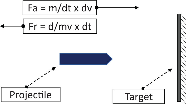
Schematic illustration of projectile force.
For the projectile nose and projectile body, Eq. (9) can be derived as follows:
where F 12 is the force acting from the body projectile on the nose projectile and F 21 is the acting force of the nose projectile on the body projectile. They have identical absolute values but in opposite directions. Large-scale deformation of the behavior of metallic materials under high pressure, high strain rate, and temperature is significant for establishing flow and strain curves. High strain rate and temperature are significant for determining flow curves and failure mechanisms under impact loads. The basic relationship of the JC model is completed by combining the aforementioned parameters [50]. Stress as a function of strain, strain rate, and temperature are material constants such as A, B, C, n, and m as provided in Eq. (10). To make it easier to understand, see Figure 3.
where
where (σ m) is the additional plastic strain and strain to fracture for a given temperature, pressure, and equivalent stress. The general expression for the fracture strain is shown in Eq. (12). Figure 4 shows the strain rate and temperature effect on the strain to fracture. The fracture strains are expressed as the ratio of the Hopkinson bar fracture strains divided by the quasistatic tensile fracture strains.
where m is the average stress and σ eq is the equivalent stress. D 1–D 3 is related to stress, D 4 is related to the strain rate effect, and D 5 is related to the temperature effect.
![Figure 3
Stress–strain data for Hopkinson bar tests at various temperatures [50].](/document/doi/10.1515/cls-2022-0200/asset/graphic/j_cls-2022-0200_fig_003.jpg)
Stress–strain data for Hopkinson bar tests at various temperatures [50].
![Figure 4
The effect of strain rate and temperature on the strain to fracture [50].](/document/doi/10.1515/cls-2022-0200/asset/graphic/j_cls-2022-0200_fig_004.jpg)
The effect of strain rate and temperature on the strain to fracture [50].
A blunt projectile of mass M and diameter d is fired into a circular ductile target of thickness H and diameter D. σ
y and
where
![Figure 5
Perforation of a thick plate [40].](/document/doi/10.1515/cls-2022-0200/asset/graphic/j_cls-2022-0200_fig_005.jpg)
Perforation of a thick plate [40].
Ballistic velocity, V BL, and residual velocity, V r, are calculated from Eqs. (15)–(17):
where V i is the impact velocity of the projectile and is a dimensionless parameter in relation to the thickness and diameter of the plate. For the velocity fields in Figure 6a–c, maximum shear sliding is reached at the end of the first phase of motion.
![Figure 6
(a) Transverse velocity profiles for the circular plate (bending hinge locates at r ¼ x), (b) transverse velocity profiles for the circular plate (bending hinge locates at r ¼ D = 2), and (c) transverse velocity profiles for the circular plate (localized shear only) [40].](/document/doi/10.1515/cls-2022-0200/asset/graphic/j_cls-2022-0200_fig_006.jpg)
(a) Transverse velocity profiles for the circular plate (bending hinge locates at r ¼ x), (b) transverse velocity profiles for the circular plate (bending hinge locates at r ¼ D = 2), and (c) transverse velocity profiles for the circular plate (localized shear only) [40].
The assumptions in this model and those considered in our study such as a steel projectile and a cylindrical nose projectile hitting a ductile metal target with the formation of a cylindrical cavity form the coherence in considering this calculation model. Thus, various thicknesses are under consideration and various impact speeds are selected. The residual velocity obtained from the analytical model is compared with that obtained from the calculation.
3 Experimental approach for ballistic test on advanced materials
The need to provide better and stronger protection against various ballistic impacts and threats has necessitated the continuous exploration and utilization of high-performance fibers, especially those from renewable sources, for ballistic applications. The development of ballistic protection materials with better performance and lower weight has received much attention in recent decades due to the increasing number of threats and insurgency cases. Due to the need to improve the ballistic performance of body armor and protective clothing, especially for military personnel, with great consideration for environmentally friendly requirements, a review of relevant studies in this field is necessary. However, before that, see Figures 7 and 8, to learn a little history of body armor.
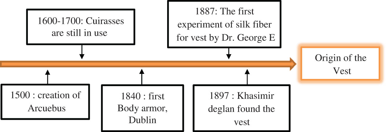
Milestone of the vest origin.
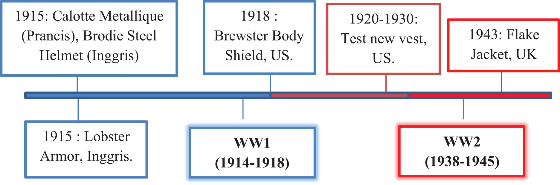
The development of the vest in the Second World War era.
For hundreds of years, metal materials have been used for body armor and protection. Larger objects, such as vehicles, are called “weight protection.” Moreover, the so-called weight protection protects larger objects, such as vehicles. However, only a few decades ago, at the end of the Second World War, a lighter solution emerged, especially for military personnel, in the form of nylon ballistic vests. However, it does not come close to the current ballistic protection offered by the aramid fibers, threads, and fabrics included in personal armor. Another advantage of ultrafine polymer filaments (not just aramid [53]) is that they offer an incredibly flexible material, which supports a high level of comfort for the wearer. To make it easier to understand, see Figure 9.

Applications of ballistics technology.
The ballistics applications of aramid fiber-based composites primarily include soft body armor. The mechanical properties of aramid and ballistic effects on fabrics and their composites have been investigated in several studies [51,54,55,56] involving both experimental and finite element method (FEM) [57,58,59,60] and determined the effectiveness of ballistic protection systems and the protection level of bulletproof vests. Recent reviews of ballistic protection [61,62] show interesting comments about failure mechanisms and highly specialized solutions in combining different materials to deal with very different threats. Studies have involved aramid fibers with different architectures, from straightforward or simply treated [63] to 3D fabrics [64], and unidirectional or multiaxial nonwrinkle fabrics, each solution being simulated under specific model conditions and tested for threats. The conclusion from the documentation carried out by the authors is that each solution must be experimentally investigated. The failure mechanism offers a robust statistical reliability design before being used in combat.
The protection of the human body from various types of risks, such as combat projectiles and sharp objects, has existed since the beginning of the history of humanity. Individuals wore clothes made from various ancient and primitive materials, such as animal skins, stone, wood, steel, copper, and others, to avoid various threats. Moreover, conventional linen, cotton, silk, and nylon fibers were used to make various textiles and laminates for clothing and protective materials against various threats involving ballistic applications [65,66,67]. For example, individual protective clothing processed from leather was used on Greek shields, various layers of silk were used in ancient Japan, and armor supported with chains in the Medieval period was also used in various protection methods. However, today's new military processes, technology-driven warfare strategies, ammunition, and weapons are on the way to encourage the creation of damage-resistant, low-density, flexible, and high-energy-absorbent ballistic armor systems [68]. In the late 1960s, a new generation of ballistic vests was established, creating a unique synthetic fiber-based material with antiballistic effectiveness. The rapid advancement of high-strength and high-modulus fibers also brought a modern era of high-quality material-based protection systems for various ballistic risks. Even then, significant research efforts were made continuously to improve the ballistic impact function of the available materials and develop advanced ballistic materials along with different mechanical characteristics for several types of technical uses involving body armor systems. As a result, various high-performance fibers with a set of structural characteristics responsible for specific ballistic impact behavior and services in compatible yarn phases, fabrics, composite layers, and others have been developed.
The development of materials, such as fiber and ballistic types, performs very well for ballistic purposes and has seen general investigation to meet the need for bulletproof capacity, high quality, and lightweight. For simplicity, this is shown in Figure 7. Many materials, especially composites, are created to improve antiballistic behavior and overcome the barriers of the previous protection. The nonuniform properties of composites due to multiphase attributes at a visible level provide an additional choice position where they reveal better characteristics in addition to new properties. High specific strength, better versatility, resistance to environmental conditions, and high impact qualities are the fundamental objectives behind using fiber-based composite materials for protection and utilization. The body shield is meant to resist small arms shots, encouraging researchers to think about fiber-reinforced composite materials [62]. The following section describes the types of materials being investigated for ballistic applications (Figure 10).
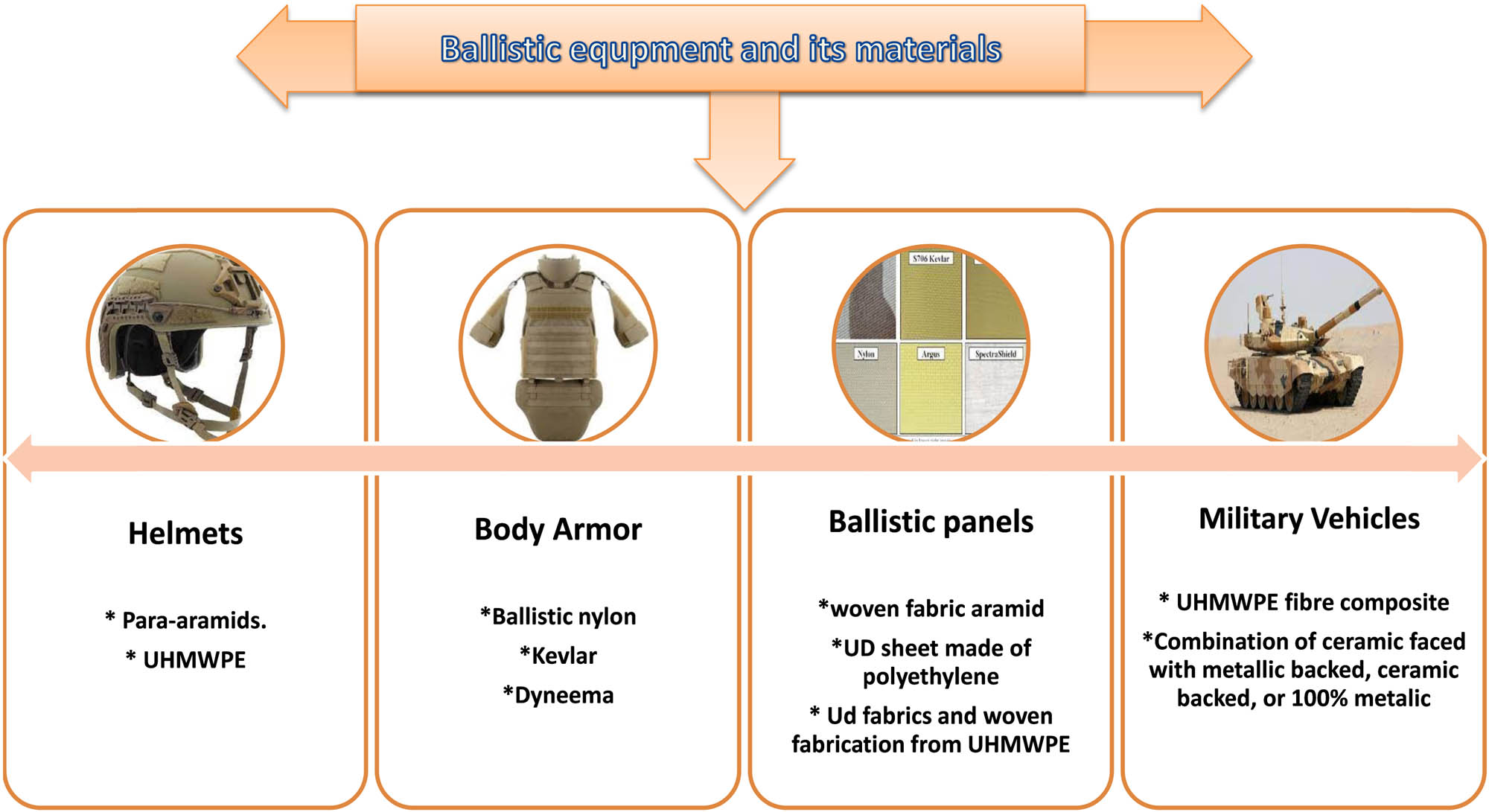
Ballistic equipment and its materials.
The two most common high-performance fibers, para-aramid and ultrahigh molecular weight polyethylene (UHMWPE), are exploited to make protective textiles because of their unique resistance to impact [69,70,71]. The registered trademarks of Twaron, Kevlar, Dyneema, and Spectra are among the most common high-performance fibers that have been used extensively in flexible personal ballistic shield processing, where it is characterized by highly desirable properties such as high strength, good chemical resistance, high ductility, and low density [72,73,74]. In addition, Zylon, Spectra, M5 Vectran, Technora, and Nextel are well-known used fibers with high performance. They exhibit unique behavior and performance in contrast to traditional fibers.
Military conflicts and wars seem to have never stopped throughout the history of the world. The level of individual and property insurance against danger in the combat zone and the state of insurgency has been made according to the development of assault weapons. On various occasions, various materials have been used for protection against attacks as indicated by the type of attack weapon. Among many, cowhide, texture, metal, and wood have played an essential role in protecting individuals and properties. Moreover, the material has been fabricated into various geometries with internal structures to increase the protective impact. For example, metal has been used as a shield to expand the adaptability of defensive layers [65,75]. Officers were challenged with more important ballistic hazards after developing different firearms with different weapons [76]. Robust, low-density materials are sought after for another era of ballistic protection.
Along with nylon fiber innovations during the 1930s, this stronger fiber was used in producing bulletproof vests toward the end of the Second World War. This innovation achieved increased assurance of weapons, lightweight, and adaptability [77]. Since then, fiber-based materials have commanded the engineering of personal defense equipment. Along with the advancement of material-reinforced composites, fiber-based composites also play an increasingly significant role as body materials for military vehicles and aircraft. This approach to designing ballistic materials attracts many considerations when different advanced fiber-based materials are manufactured today, for example, aramid (e.g., Kevlar and Twaron), UHMWPE (Dyneema and Spectra), poly-phenylene benzisoxazole (PBO) fibers (e.g., Zylon), and PIPD (e.g., M5).
However, Zylon is considered susceptible to hydrolytic and photolytic damage and consequently was not proposed for use in ballistic protection [78]. M5 fiber experiences degradation. However, it causes less degradation than PBO from radiation exposure and increased humidity. At the same time, it may exhibit a weakness in ballistic build-up rates [79]. Likewise, with the situation, the fibers for ballistic protection are mostly aramid and UHMWPE fibers. From the armed clashes that have developed over time, it tends to be inferred that central deployments in defense layer security zones have been coordinated in the assembly of new types of fighting machines toward the modernization of certain advances used to assemble their principal segments and subassemblies. Modern armored vehicles are equipped with the usual homogeneous protective material, generally made of steel or aluminum alloy.
The trend these days, both broadly and universally, is to inquire about new rebar plates, which are lighter because they are sufficiently resistant to various hazards. The actual productivity requirements of armored vehicles, including fast shifting, extended driving range, and enhanced ballistic protection, substantially add to the growing effectiveness of reinforced vehicles and, therefore, higher levels of endurance at the forefront. The current trend is the demand to acquire armor plates made of low-density multilayer composite materials, which ensure piercing protection and combined ammunition impact, for example, reduced overpressure and abundance [80].
In addition, the engineering of fibers in composites used for ballistic protection has been influenced by the structure of materials such as those used in the design of soft body armor layers; therefore, many composites used for ballistic protection have a woven texture comparable to that used in body armor. This way, glass-based and para-aramid composites for ballistic applications essentially involve plain weave textures, which are generally coupled with phenolic epoxy or polyvinyl butyral (PVB). In correlation, UHMWPE fibers were used in a cross-handle layout (0 degrees/90 degrees) with thermoplastic resins to reduce fiber fracture during fabrication [81]. However, early studies did not account for woven UHMWPE fibers [82,83].
What is essential is that ballistic composites must have a high fiber count with generally weak interlayer adhesives [84,85,86]. They are not inherently good composites; matrix substance may be as low as 10% wt/wt [87]. Delamination is argued to be an effective system in which energy is propagated from the point of effect in ballistic protection composites [83,88,89,90,91]. Manufacturing parameters are very important but rarely investigated in the open-access literature. The impact of heat stress time on the ballistic shielding properties of Kevlar phenolic/PVB composites suggests that more stress time reduces exhibit, possibly due to the expanded interlaminar bonding [92].
Research on the impact of ballistics on advanced materials has been carried out before. Research conducted by Goda and Girardot [93] researched ceramics and composites Kevlar-29 with a honeycomb core shape using a blunt cylindrical projectile. The numerical results show that the ballistic impact performance highly depends on the properties of the cohesive material, the stacking order, and the woven fabric material. In contrast, the more negligible contribution of the supporting conditions to the ballistic perforation characteristics is considered. Rahimijonoush and Bayat [94] investigated the marine field by analyzing the performance of titanium sandwich panels against impact loads from hemispherical projectiles. The results show that the impact energy is mainly absorbed by the back face sheet in the symmetrical sandwich panels. The ballistic limit increases almost linearly with the increasing back or front face sheet thickness in specimens of the same weight.
Research in the field of aeronautics was carried out by Chatterjee et al. [95] analyzed the performance of a composite sandwich panel against a 9 mm projectile load with an average speed of 400 m/s. Due to the incorporation of dilatant liquid within SCP, it can absorb 20.24% of the energy incident on it. The amount of energy absorbed is 43.96% greater than that absorbed by the hollow composite, and the percentage increase in energy absorbed per unit mass is 22.43%. This enables the constructed SCP to be used in applications requiring enhanced energy dissipation. Yu et al. [96] conducted marine research targeting a Y-shaped core sandwich using a blunt-shaped projectile. The study concluded that the impact resistance of a composite sandwich structure with a Y-shaped core is superior to that of a laminate.
Research by Khaaire et al. [97] in the naval industry aimed to determine the performance of a honeycomb core cylinder sandwich against ballistic loads of cone-nosed projectiles. The study concluded that when the skin and cell wall thickness changed from 0.7 to 2.0 mm and 0.03 to 0.09 mm, the ballistic limit increased by 72.2 and 10.9 m/s, respectively. However, when the side length changes from 3.2 to 9.2 mm, the ballistic limit is reduced by 9.9 m/s. Wu et al. [98] investigated an armored composite system using an aramid–carbon hybrid FRP laminated composite structure when exposed to ballistic loads from a 7.62 M61 AP projectile. The conclusion was that the main failure modes of FRP laminates are fiber compression failure and tensile matrix failure, both of which can also be affected by changes in the arrangement of the FRP laminates. When the carbon fiber is stacked on top of the FRP laminate, the fiber compression failure area and the matrix tensile failure area are the lowest.
Research on shipbuilding structures was carried out by Yang et al. [99], namely regarding the performance of composite double-arrow auxetic structures against ballistic loads from hemispherical-shaped projectiles. The study concluded that the METC auxetic structure has a relative density of 16.66, which is 23.06% larger than the auxetic structure with a relative density of 9.08%. The ballistic limit speed increased by 35.56 and 54.89%, along with the increase in the relative density from 9.08 to 16.66 and 23.06%, which was validated by the experiment. Vescovini et al. [100] studied the composite structure using a hybrid interplay composite of Kevlar woven and S2 glass when ground with 0.357 Magnum FMJ. The study concluded that the deviation at the ballistic limit is always lower than 5.33% and a maximum of 3.87% at an impact speed of 430 m/s, close to the ballistic limit. Moreover, although the numerical ballistic curve shows a generally smoother transition to the linear part, it fits very well with the experimental one.
Mohammad et al. [101] proved that the ballistic performance of monolithic shell targets decreased by 6.49%. In contrast, layered targets showed a 3.88% decrease in impact-resisting capacity on tilt impact. Han et al. [102] analyzed that the deviations of the predicted 2, 4, 4.82, 8, and 9.94 mm target ballistic velocities from the corresponding experimental values were, respectively, 12, 3, 0.1, 0.0, 4.2, and 4.9% for the simulations of 9.0, 17.5, 21.5, 24.2, and 26.3%, respectively. Research on the impact of ballistics has been carried out in various fields.
Over the past two decades, several elite fibers have been produced for ballistic impact protection uses. These fibers are generally light and have incredibly high-energy absorption qualities. A significant part of composite reinforcement is fiber. Although carbon fiber and glass fiber are commonly used fortresses for structural parts, from the perspective of ballistic applications, the widely used fibers are high-molecular-weight polyethylene, para-aramid, poly-diimidazo-pyridinilene-dihydroxy-phenylene, and PBO [54,103] and many other fibers. These fibers generally have the mechanical properties of different ballistic-grade fibers. These fibers should have lightweight, high strength, and high modulus. To make it easier to understand, we have summarized an explanation of the types of advanced antiballistic materials in Table 3.
Mechanical properties of advanced material antiballistic-grade fibers [104]
| Material | Strength to weight (kN m)/kg | Ultimate strength (MPa) | Density (g/cm3) | Price per 1 m2 or 1 kg on Alibaba, USD |
|---|---|---|---|---|
| UHMWPE | 3,619 | 2,300–3,500 | 0.97 | $10.22 |
| Kevlar | 2,514 | 2,757 | 1.44 | $6.96 |
| Carbon fiber | 2,457 | 4,137 | 1.75 | $6.00 |
| Carbon laminate | 785 | 1,600 | 1.5 | $5.00 |
| E glass fiber | 1,307 | 3,450 | 2.57 | $3.00 |
| E glass laminate | 775 | 1,500 | 1.97 | $3.10 |
| Polypropylene | 89 | 19.7–80 | 0.91 | $1.72 |
| S glass fiber | 1,906 | 4,710 | 2.47 | $4.00 |
| Spider silk | 1,069 | 1,000 | 1.3 | $2.80 |
| Balsa axial load | 521 | 83 | 0.16 | $0.60 |
| Steel alloy ASTM A36 | 254 | 400 | 7.8 | $0.45 |
| Aluminum alloy | 222 | 248–483 | 2.63–2.8 | $1.20 |
| Oak | 87 | 65 | 0.75 | $1.50 |
| Epoxy | 26 | 12–30 | 1.23 | $4.85 |
| Nylon | 69 | 75 | 1.15 | $2.49 |
Advanced material technology innovation in recent years and the development of more substantial raw materials have made a big difference in body armor. Today's most common materials used in more sophisticated body armor are ultrahigh-molecular-weight polyethylene (UHMWPE), along with aramid fibers. UHMWPE has contributed to a considerable improvement compared to Kevlar, an aramid product. Kevlar was the only option for body armor not so long ago. However, in recent years, we have seen more and more soft protective panels made of UHMWPE. DSM manufactures this material under the Dyneema brand, and Honeywell's UHMWPE product is called Spectra. The weight factor shows that UHMWPE is the strongest fiber currently available. The Dyneema Force Multiplier SB115 and SB117 soft armor material is an upgrade from the old Dyneema SB21 fiber. SB115 and SB117 are 28% stronger, so vests made with this fiber are about 28% lighter. Moreover, these fibers are substantially more flexible, which is another improvement. The armored panels are now being manufactured with the SB115 and SB117. The US military has used the Dyneema Force Multiplier material in their body armor.
4 Idealization of ballistic test on curved-layered object using computational approach
It is not only humans and civilizations that have experienced evolution or change; it turns out that even though the software has experienced a transition from time to time in line with industrial and technological developments, the software itself has also transformed. Reflecting on the history of development during the first three decades of the computerized era, the main challenge is developing computer hardware that can reduce data processing and storage costs. Furthermore, software engineering has developed since it was first created in the 1960s. The main focus of its development is to develop practices and technologies to increase the productivity of practicing software developers and the quality of applications that users can use. During the 1980s, the rapid advancement of microelectronics resulted in better computer capabilities at a lower cost. However, the problem now is different, and the main challenge is to reduce costs and improve the quality of computer-based solutions (solutions implemented using software).
Software is an interpreter of commands run by computer users to be forwarded or processed by the hardware. With this software, a computer can execute a command. At this time, software’s ability is excellent. That is why experimenting and spending much money to analyze and determine results is needed. In engineering, the software is very diverse, from essential to expert. Here are some of the software used in engineering, especially in anti-ballistic test analysis.
4.1 Calculation by numerical approach for ballistic phenomenon
Finite element analysis (FEA) is very useful for engineers who need to perform structural analysis in their work. FEA allows us to analyze stresses and deflections in complex structures. Typically, the structure will be modeled in a 3D CAD program and then transferred to FEA for analysis. Fortunately, many types of FEA are integrated with CAD software today, making the transition between software easier. Examples of popular FEA software include ANSYS and Nastran.
In this discussion, we review the analysis software commonly used to study the ballistic impact based on numerical modeling. Several researchers have promoted and developed numerical models that rely on numerical methods, such as finite differences and FEMs. There are several FEM-based commercial software such as ANSYS, ABAQUS, LS-DYNA, and DYNA 3D, which are commonly used to build shot simulation models, and, moreover, the ballistic impact behavior of the material [105–113]. Each FEM task should be treated individually and with caution because an excessive number of variables may have a negative impact on the results. In the case of bullet penetration, the constitutive equation is more complex due to additional criteria, which is given as follows:
where K is the structure stiffness matrix; M is the inertia matrix; C = αM + βK is the damping matrix (where α and β are constant coefficients);
The aforementioned considerations show the multitude of factors influencing the solution of tasks in the field of impact loads. An engineer facing a problem in this area must compromise between the accuracy of the solution and the number of factors considered.
With the change in the projectile velocity, the stress and strain values in the sample change. Comparing them with each other is an engineering challenge and depends on many input parameters defined when solving a FEM task. As mentioned earlier, the influence of selected input parameters on the velocity of the projectile behind the sample with a thickness of 4 mm was analyzed. During the calculations, the influence of the following parameters was taken into account:
A – material constant of the Johnson–Cook (J–C) model;
B – hardening parameter of the J–C model;
n – strengthening exponent of the J–C model;
C – J–C strain rate parameter;
d 1, d 2, d 3 – J–C failure criterion;
u failure – displacement at failure;
µ – coefficient of friction.
To be able to simulate on a macro scale, it was decided to perform simulations on a microscale, relating it to the conducted experiments. The simulation was calibrated using the boundary conditions and the load presented in Figure 11. Several descriptions of computational mechanics simulations are shown in Figures 11–14.
![Figure 11
Geometry and discretization of the projectile and the sample [111].](/document/doi/10.1515/cls-2022-0200/asset/graphic/j_cls-2022-0200_fig_011.jpg)
Geometry and discretization of the projectile and the sample [111].
![Figure 12
The shape of the projectile and the morphology of the penetration of the sample depends on the used projectile model for a sample with a thickness of 4 mm [112].](/document/doi/10.1515/cls-2022-0200/asset/graphic/j_cls-2022-0200_fig_012.jpg)
The shape of the projectile and the morphology of the penetration of the sample depends on the used projectile model for a sample with a thickness of 4 mm [112].
![Figure 13
Side hitting projectile due to the torque from the impact at an angle [112].](/document/doi/10.1515/cls-2022-0200/asset/graphic/j_cls-2022-0200_fig_013.jpg)
Side hitting projectile due to the torque from the impact at an angle [112].
During calibration, the values of the given input parameter were changed by +50%, and then FEM calculations were performed. Such a procedure makes it possible to determine the influence of a single parameter on the results obtained. An analysis was made of how the percentage changes in individual parameters affect the percentage change in the final results. In this way, the input parameters for which the projectile velocity after the sample was consistent for the simulation and the experiment were determined. The parameter list used in the final model is presented in Table 4.
Material constants for 1.3964 steel [111]
| Material | Elastic | J–C plasticity | J–C failure | ||||||
|---|---|---|---|---|---|---|---|---|---|
| E | v | A | B | n | C | d 1 | d 2 | d 3 | |
| 1.3964 | 240 GPa | 0.3 | 302 | 1,250 | 0.3334 | 0.006 | 0.02 | 0.05 | 0.5 |
The stage of the work was to determine the failure criterion for steel 1.3964. Due to the fact that the J–C viscoelastic model was used to describe the plastic characteristics, this study uses a simplified Johnson–Cook failure model in the form of Eq. (19):
where d 1 is the strain for which ultimate strength is assumed; d 2 and d 3 are material constants describing the reduction in material stiffness; and η is the triaxiality.
To complete the task as fully nonlinear, a failure model for the projectile itself should also be proposed. Most studies in this area use the projectile as a rigid body to reduce the computation time. The validity of such a solution has been verified. Bu using the boundary conditions shown in Figure 11, a series of simulations were carried out with the use of elastic, elastic–plastic, and elastic–plastic with the failure criterion material models. Material data for the projectile were obtained from the literature and are presented in Table 5.
Material properties for the shell and the bullet core [111]
| Part of the projectile | Elastic | J–C plasticity | J–C failure | ||||||
|---|---|---|---|---|---|---|---|---|---|
| E | v | A | B | n | C | d 1 | d 2 | d 3 | |
| Core | 210 GPa | 0.3 | 234.4 | 413.8 | 0.25 | 0.0033 | 5.625 | 0.3 | −7.2 |
| Shell | 120 GPa | 0.33 | 448.2 | 303.4 | 0.15 | 0.0033 | 2.25 | 0.0005 | −3.6 |
Based on the FEM simulations, it was noticed that the projectile material model has a significant impact on both the shape and the morphology of the puncture (Figure 12) as well as on the velocity of the projectile behind the sample.
![Figure 14
Model meshing with configuration 12 layers [152].](/document/doi/10.1515/cls-2022-0200/asset/graphic/j_cls-2022-0200_fig_014.jpg)
Model meshing with configuration 12 layers [152].
This causes a reduction in forward speed and increases the projectile's area of interaction with the next obstacle. This has significant consequences in the analysis of hull destruction (Figure 13). This article also aims to raise awareness of bullet resistance in steel structures. Around the world, research is constantly being carried out on implementing new solutions to increase the resilience of steel structures.
This technique is generally an efficient method as a function of cost and time compared to the experimental method because it minimizes the experimental work. However, it still requires sizeable computational capacity and resources to simulate the process. In general, three main numerical approaches are commonly used and are known as pin-jointed models [55,114–116], full 3D continuum models [117–120], and mesoscale unit-cell-based models [121–125] for simulating texture structures. Regarding texture simulation, the pin-joint, and the 3D continuum models consider the woven fabric construction method using weft and warp yarns. In contrast, the unit cell model for woven texture combines crossover [126].
Moreover, the model has shown promising effectiveness in estimating ballistic impact response for multiple texture boards contrasted with 3D continuum and pin-jointed models [127]. However, such a model also has problems analyzing the behavior of major and minor yarns in texture because the yarns are not explicitly simulated, and there are differences in the associated stress distribution [128]. For example, a numerical model for estimating the ballistic behavior of Kevlar 29 against various double-ended cylinder shots was developed to predict the ballistic capacity, fracture mode, and deformation of the target. Furthermore, it provides an opportunity to differentiate the impact behavior of the fabric on double-nose projectiles, single-nose cones, and flat projectiles.
The critical effect of nose geometry on the ballistic behavior of the designed texture has been illustrated, and a minimum ballistic capacity has been observed in the shot of the conical geometric shape. The simulations show that the nose shape of the projectile has a low and high influence on the ballistic capacity velocity for thick and thin targets, respectively [129]. The increase in delamination of a nonwrinkled fabric-type composite material was analyzed using various numerical simulation methods, such as stiffness averaging, penalty method, and modified virtual crack closure techniques. The simulation findings provide a better relationship with the experimental results based on the load–displacement curve and the shape of the defect [130].
An alternative FEM model was also developed to investigate the effect of various layer adjustment angles (3-ply align-laid (0/0/0) and angle-laid (0/30/60)) on the ballistic impact behavior of multiple layers of UHMWPE board material. According to the three-ply modeling, the textured board exhibits a crucial velocity with the increased energy absorption obtained by the angle-laid board due to isotropic better interplay [131]. It is also usually revealed that it is tough to truly understand and photograph ballistic impacts using exclusively exploratory, experimental, numerical, or analytical strategies. Different authors use a mix of exploratory, numerical, experimental, and explanatory methodologies to get a better interpretation and conduct a practical examination of data during ballistic impact systems [132–140]. Blunt injury resistance of various textures (plain weave, UD laminate, and multi-hub texture) processed from high-strength fibers using experimental and numerical methodologies have been carried out. The highest estimates of the subsidence depth and measures of energy transferred from each texture were contrasted and standardized based on their areal density and thickness.
The two methodologies show that most textures provide a comparable level of protection; however, the best blunt injury resistance is provided by the multi-hub texture and the least by the plain weave texture, depending on the standard quality [141]. Numerical modeling of the microstructure followed by exploratory examination has been completed on the ballistic impact hazard of a 3D symmetrical woven texture perforated under a narrow barrel-shaped rigid shot. The results show that numerical modeling can investigate the impact of damage better than experiments during contrasting damage morphology and shot residual velocity after penetration. However, for the better improvement of the 3D orthogonal woven fiber structure, consolidated experimental and numerical examinations are also required in both the material and structural aspects. Supplements are needed from both material and structural perspectives [142]. In addition, other examinations include perforating models. Consolidated hypotheses and semi-empirics were created, including the impact of short-term pressing and long-term dynamic perforating on thick-area composites on ballistic inlets. The results show a good relationship with the FE analysis of the comparative states [143].
The ballistic behavior of various materials involving ballistic materials (Kevlar) to extended explosive gadgets and improvised explosive devices is tentatively independently examined before making combinations of various materials to build the ultimate goal of efficient protection. In addition, numerical modeling using DYNAFAB and LS-DYNA has also been carried out to establish suitable and improved structural parameters of the objectives. Excellent agreement was reached between the model and experimental results [144]. Various 3D woven texture composite laminates were associated with shockwave dispersion and energy balance according to analytical models to predict their ballistic impact behavior against rigid round shots. A structured analysis model of shear termination and tensile fracture during conical deformation and solution was introduced among the many breakdown and energy-absorbing systems.
In addition to these definitions, investigations on certain laminates were also applied to agree on the analyzed results [145]. The exploratory information on the ballistic behavior test of 3D interlocked twist-woven texture against FSP was approved using numerical simulation with dynamic and static situations. According to the investigation, the numerical results of dynamic cases showed a reasonable estimate of the impact behavior of 3D woven textures rather than static case values [146]. In addition, different researchers have also carried out various material impact analysis techniques. The micromechanical method [109,147–149] is used where the shape of the texture is generally exemplified by a representative volume cell to convey the entire texture structure through repeated interpretation. Various parameters, for example, distance, strain, and stress, are determined by the cell being analyzed by force balance or various potential energy techniques. Moreover, different methodologies consider the assumptions on different texture practices at various scales due to the intrinsic multiscale nature of texture, known as the constitutive multiscale strategy [125]. Variational methods are alternative numerical techniques for monitoring models using fluctuation standards, for example, the minimum potential energy principle, Reissner's variational guideline, the Rayleigh–Ritz strategy, and Galerkin strategy [150,151]. Many methods have been developed in modeling and calculation to increase knowledge and make it easier to calculate and design an antiballistic. In the past, calculations have been carried out for antiballistic designs, but it may still take long to design.
4.2 Design testing using simulation and analysis
Based on the current development of military technology, there are many challenges that must be faced in order to remain competitive. High-quality antiballistic products are needed to obtain a sense of comfort and safety for users. Thus, product developers and engineers must do their best to achieve these quality demands. Product developers and engineers must answer several challenges regarding the reliability of a product, including strength, repeated impact resistance, bullet heat resistance, weight, and not hindering movement.
In the industrialized world of the past, to make a quality product, several prototypes had to be made, and tests were then conducted to assess the quality of the product. However, prototyping and testing are costly and time consuming. Several additions make a difference in the design process today. One of them is testing to see if the design product meets the requirements and works as expected. The demands of the user's demands can be obtained by conducting a reference study to identify and determine the requirements, then brainstorming and evaluating whether there is a possibility of modifying the product.
All this is achieved by modeling the product parts using CAD software to visualize them properly. Several CAD programs now release packages that include modeling and FEA capabilities. Therefore, with FEA, some models created in the previous design process can be used to simulate and derive a solution that may be the best product. If redesigning is required, it is only necessary to design parts that need to be improved according to the data from the analysis. The simulation results using FEA are able to approach the actual results, so there is no need to spend a considerable investment to produce one type of prototype. For example, in the research conducted by Pirvu et al. [152], a simplified simulation of the impact bullet-stratified pack was run whilst restraining one or more parameters involved in the pack testing. The isothermal model has 14 solid bodies: 12 identical layers considered a group of bodies (with the option multiple materials), overlapped and rigidly fixed on their contour, and 2 bodies for the bullet (also multiple materials) with bonded connections (Table 6 and Figure 14). One layer's dimensions are (6 × 10–2) m × (6 × 10–2) m × (0.6 × 10–4) m. As the impact direction is the same as the model's symmetry axes, the simulation is run for a quarter. The contact among bodies takes into account the fact that the friction coefficient between layers is 0.4, characteristic of polyethylene sliding against itself, and that the friction coefficient between a layer and the bullet jacket is 0.3.
Characteristics of the model [152]
| Body | Nodes | Elements |
|---|---|---|
| Layer | 1,250 | 576 |
| Pack with 12 layers | 18,816 | 8,748 |
| Bullet (jacket + core) | 1,432 | 6,289 |
| Bullet jacket | 739 | 2,211 |
| Bullet core | 996 | 4,078 |
The meshing (Figure 14) is presented for the pack with 12 layers. The maximum size of an element is 5 × 10⁻⁴ m. The initial condition refers to the bullet velocity just before impact (here 400 m/s). The presented simulation on ballistic packs for individual armor with 12 layers, even if simplified, estimated the failure of five layers, and experiments validate this. Thus, a simulation at the macro level may be helpful in a rough estimation of the pack's thickness (or the number of layers). The simplifying hypotheses, the material properties, and the conditions during simulation (isothermal and with friction) have realistic values, and the results may shorten the range of some parameters, which is the number of layers supposed to resist a specific threat [152]. Another analysis project that was carried out is shown in Figures 15 and 16.
![Figure 15
Finite element analysis that highlights maximum tension recorded on the basis of von Mises criterion involves maximum deformation of the composite [153].](/document/doi/10.1515/cls-2022-0200/asset/graphic/j_cls-2022-0200_fig_015.jpg)
Finite element analysis that highlights maximum tension recorded on the basis of von Mises criterion involves maximum deformation of the composite [153].
![Figure 16
Finite element analysis that highlights the areas that suffered major destruction effects both for surface impact armor and for the projectile that penetrated the armor [153].](/document/doi/10.1515/cls-2022-0200/asset/graphic/j_cls-2022-0200_fig_016.jpg)
Finite element analysis that highlights the areas that suffered major destruction effects both for surface impact armor and for the projectile that penetrated the armor [153].
Based on Figures 10 and 11, more than 95% of the projectile's kinetic energy has been transmitted to the cellular composite armor. Playing network at this time is difficult because the network that can no longer represent faithfully takes two bodies' deformations due to the impact. FEA details take much work, even in the fast finite element (FFE) system. However, it can also be performed as a presentation of the ballistic behavior in FFE network representation. The modeling system generates a detailed representation of volumetric deformation around the projectile in the final stage to unlock the armor. Modeling highlights some of the features of plastic deformation we presented earlier for electron microscopy analysis, which identifies the matrix plasticity around the projectile shown in Figure 11. FEA highlights maximum impact stress areas for a projectile with a conical tip penetrating the composite. Maximum tension recorded based on the von Mises criterion involves maximum deformation of the composite (Figure 13). FEA highlights the areas that suffered significant destruction effects for surface impact armor and the projectile that penetrated the armor [153]. In another article, Abtew et al. [61] showed an FEA used to demonstrate the ballistic mechanism and design the structure of different composite textile materials. It is shown in Figures 17 and 18.
![Figure 17
The fabric impact area hit by the projectile [154,155].](/document/doi/10.1515/cls-2022-0200/asset/graphic/j_cls-2022-0200_fig_017.jpg)
![Figure 18
Illustration of ballistic impact on (a) multilayered fabric panel by a cylindrical projectile, (b) reaction of the primary yarns in one layer of fabric in multilayer textile-based body armor [159], (c) impacted fabrics [155], and (d) energy-absorbing mechanism for woven fabrics [160].](/document/doi/10.1515/cls-2022-0200/asset/graphic/j_cls-2022-0200_fig_018.jpg)
Kiciński and Kubit [112] used the FEM to calibrate the material constants and boundary conditions necessary to be used in simulations of the entire hull model. How projectile modeling affects the FEM calculation results was assessed. After obtaining the simulation results consistent with the experimental results, using the model of a modern minehunter, the resistance of the ship’s hull to penetration by a small-caliber projectile was tested and is shown in Figure 19. Afterward, by using photos and promotional materials [156], the geometry of the ship’s hull was created, which is shown in Figure 20.
![Figure 19
The 4 mm thick hull bullet penetration results [112].](/document/doi/10.1515/cls-2022-0200/asset/graphic/j_cls-2022-0200_fig_019.jpg)
The 4 mm thick hull bullet penetration results [112].
![Figure 20
Modern minehunter geometry with random cabin layout [112].](/document/doi/10.1515/cls-2022-0200/asset/graphic/j_cls-2022-0200_fig_020.jpg)
Modern minehunter geometry with random cabin layout [112].
Based on Figures 19 and 20, it can be seen that the simulation shows that the plating thickness significantly impacts the destruction inside the ship. Furthermore, this article considers the best possible case of hitting each hull stiffener. In the most unfavorable situation (the projectile only hits the bulkhead), it is possible to penetrate the ship through almost all ship compartments if it were made of 4 mm thick sheets. It is worth noting that, in the case under consideration, only the 7.62 mm bullet was tested. For larger calibers, the damage possible would be much more extensive.
Dhode et al. [157] conducted a FEA to assess the behavior of steel “SAM2X5-630” under the impact load of a car side door and the impact of a bullet on the bulletproof jacket to which the material is assigned. The deformation and stresses are calculated and compared to understand the behavior of metal alloy. The methodology is described for two applications: car door impact and bullet impact on vest. To facilitate understanding, we present flowcharts in Figures 21 and 22. The results of applying the methodology are shown in Figure 23.

Methodology of car door impact.
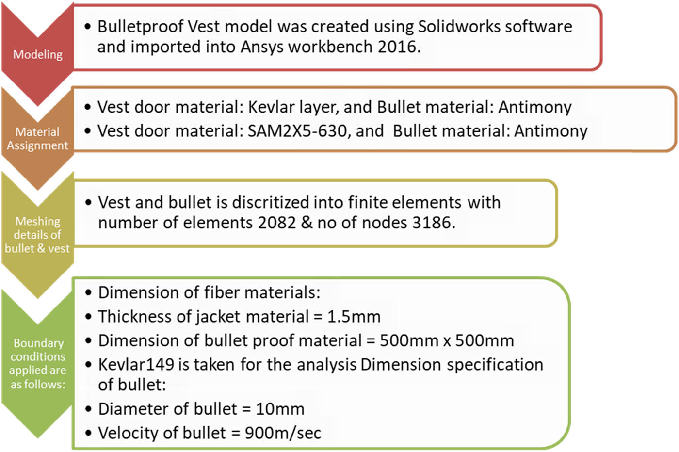
Bullet impact on vest modeling.
![Figure 23
Directional deformation in aluminum alloy [157].](/document/doi/10.1515/cls-2022-0200/asset/graphic/j_cls-2022-0200_fig_023.jpg)
Directional deformation in aluminum alloy [157].
Directional deformation in Al alloy applied to the door using Ansys is very useful and can be very helpful. The displacement or deformation that occurs during the impact can be found. Zochowski et al. [158] researched the ballistic impact resistance of bulletproof vest inserts containing printed titanium structures designed and simulated using FEM. The discretization of the simulation components is shown in Figure 24.
![Figure 24
Results of simulation for S1 structure: (a) location of the impact point; (b) final deformation; (c) distribution of effective plastic strain in the titanium structure; (d) shape of the hollow in the ballistic clay; and (e) plot of the projectile energy against time [158].](/document/doi/10.1515/cls-2022-0200/asset/graphic/j_cls-2022-0200_fig_024.jpg)
Results of simulation for S1 structure: (a) location of the impact point; (b) final deformation; (c) distribution of effective plastic strain in the titanium structure; (d) shape of the hollow in the ballistic clay; and (e) plot of the projectile energy against time [158].
Figure 24 was produced using HyperMesh software. The size of the elements was chosen so that their number keeps up the calculations. On the other hand, it allows for precise reproduction of the object geometry and obtaining accurate results. In addition, the ballistic clay mesh was refined in the zone of the projectile impact point to limit the number of elements in the armor model. The distance between adjacent nodes ranges from about 0.25 mm in the projectile impact zone to 1 mm in the undeformed armor area. The boundary conditions are set such that the numerical model reproduces the features of the real phenomenon as much as possible. Pulungan et al. [161] conducted an analysis of a bulletproof vest made from carbon fiber composite and hollow glass microsphere in absorbing energy due to the projectile impact. The selection of material types to be used in this study, which aimed to provide the right material properties of the specimen of material used, is shown in Figure 25. Figure 26 shows how the selection process is very important in using Ansys in this study, using the smallest meshing value with the aim of achieving better results. Figure 27 shows that the load shown in Figure 28a aims to give impact capability to the bullet by adding the speed of the bullet according to the standard test using the III-A type of weapon that is 426 m/s. Then, in Figure 28b, it provides fixed support on both sides of the vest design, which is intended as a barrier so that during the collision, the vest design remains in the desired position.
![Figure 25
The choice of material in the vests and bullet models [161].](/document/doi/10.1515/cls-2022-0200/asset/graphic/j_cls-2022-0200_fig_025.jpg)
The choice of material in the vests and bullet models [161].
![Figure 26
Meshing selection of the impact test [161].](/document/doi/10.1515/cls-2022-0200/asset/graphic/j_cls-2022-0200_fig_026.jpg)
Meshing selection of the impact test [161].
![Figure 27
Design of the bulletproof vest: (a) provision of the burden of a speeding bullet 426 m/s and (b) fixed support [161].](/document/doi/10.1515/cls-2022-0200/asset/graphic/j_cls-2022-0200_fig_027.jpg)
Design of the bulletproof vest: (a) provision of the burden of a speeding bullet 426 m/s and (b) fixed support [161].
![Figure 28
Simulation of the vest developed from the ballistic package 1 on the avatar. (a) and (b) checking the aspect of the vest front/back, (c) and (d) checking the matching body product, (e)–(g) 3D visualization of the vest as a mesh of triangles [162].](/document/doi/10.1515/cls-2022-0200/asset/graphic/j_cls-2022-0200_fig_028.jpg)
Simulation of the vest developed from the ballistic package 1 on the avatar. (a) and (b) checking the aspect of the vest front/back, (c) and (d) checking the matching body product, (e)–(g) 3D visualization of the vest as a mesh of triangles [162].
Based on Pulungan et al.’s study, a bulletproof vest with a thickness of 20 mm is able to absorb the kinetic energy of a projectile of 138.77 joules of energy. The projectile's kinetic energy will be transferred to the bulletproof vest and converted into kinetic energy and internal energy in the bulletproof vest. A bulletproof vest with a thickness of 20 mm produces 138.77 joules of energy, which is safe to use. Moreover, based on the NIJ 0101.06 standard, the projectile's penetration against the bulletproof vest should not exceed 44 mm. Based on the report of Major General Julian S. Hatcher, a US Army ordnance expert noted that the total energy of 170.2 joules is capable of causing injury and capable of incapacitating the victim [161].
Body armor design is generally reserved for men, but Toma et al. [162] have carried out something different by improving the fit and performance of bulletproof vests on women. Some designs and analyses are presented in Figure 28.
The steps to develop the virtual functional model were as follows: (a) 2D pattern design from the data in the model dimension table and correlation with the actual size of the bulletproof vest using OPTITEX's Pattern Design Software; (b) simulation of the functional model of the bulletproof vest on an avatar using Optitex 3D Suite Software; (c) evaluating the fit of the product on the body, such as the distance between the textile material and the body surface, the tension developed in the textile material, and its orientation using 3D software functions such as tension scale and technical characteristics of material [162].
To complete the analysis, we can look at the analysis of injury to occupants of light armored vehicles by fragment after-effects of rifle projectiles already conducted by Li et al. [163]. To study the injury effect of the fragment after-effect on the occupant, a 12.7 mm multifunctional bullet was tested on 10 mm armored steel to obtain the mass distribution of the fragment after-effect at different speeds. Then, a finite element model of the fragment after-effect on the FEM of the human thorax with soft body armor was established. The impacts of bullet fragments after different effects are obtained using numerical simulation. As a result, the stress and pressure changes of human model after the impact can be derived as presented in the study. The obtained effects are the basis for further evaluating the fragment effect injury to the occupants in light armored vehicles. To make it easy to understand, see Figures 29 and 30.
![Figure 29
The evolution of the stress field of the thorax epidermis [163].](/document/doi/10.1515/cls-2022-0200/asset/graphic/j_cls-2022-0200_fig_029.jpg)
The evolution of the stress field of the thorax epidermis [163].
![Figure 30
The evolution of the stress field of organs [163].](/document/doi/10.1515/cls-2022-0200/asset/graphic/j_cls-2022-0200_fig_030.jpg)
The evolution of the stress field of organs [163].
Figure 29 shows the evolution of the stress field of the thorax epidermis after the impact of after-effect fragment cloud. When t = 40 μs, the stress field appears on the epidermis, while a stress field appears on the soft armor at t = 25 μs. There is a time difference between them, which also reflects the propagation of stress from the outside to the inside. The stress is maximum at the equivalent impact point and gradually decreases around it. The epidermal stress spots gradually become larger with time, reaching the maximum at t = 160 μs, with a diameter of approximately 12.96 cm and an area of approximately 67 cm2. The maximum stress at this time is 0.169 kPa.
Different from the stress spot formed by bullet impact, the bullet forms a circular spot with the impact point as the center, and for the fragment cloud, it is an irregular shape due to the difference in the impact position and time of the fragment, and this is shown in Figure 30.
Figure 30 shows the evolution of the stress field of each organ after the impact of the fragment cloud. When t = 80 μs, the stress field appears on the right lung (the first impact point is close to the right lung), with the impact point as the center, and propagates around in an approximately circular shape. The stress appears 40 μs later than the skin because the stress wave propagates from the outside to the inside, and there is a time lag. At t = 110 μs, the stress wave propagates to the heart near the right lung, and at t = 170 μs, it propagates to the liver and left lung. Among them, when t = 200 μs, the stress point of the heart is the largest, and its area accounts for approximately two-thirds of its surface area.
A finite element model of the human body is suitable for Chinese people, and finite element simulations are performed based on this model. The after-effect fragment formed by the armor-piercing projectile is taken as the projectile body. The results are compared with data in similar studies and are partially comparable in some data. To lay the foundation for further establishing the quantity–effect relationship between human mechanics response and physical injury, the simulation results can provide a basis for behind armor blunt trauma (BABT) studies [163]. This research conducted by Li et al. can provide a reference for evaluating the damage caused by side-effect fragments from armor-piercing projectiles and optimizing occupant antiballistic measures on light armored vehicles.
On the other hand, there is an approach to teaching projectile motion using MATLAB simulation. The main purpose of developing the code was to achieve better qualitative and quantitative understanding of the intricate factors (e.g., drag) influencing projectile motion, which are usually not discussed in standard texts. Nevertheless, another benefit of using such an approach is accustomed to some advanced MATLAB features. From elementary physics, projectile motion occurs when an object is thrown, making some angle with the horizontal at a certain initial velocity, or dropped and moved under the influence of gravity. There is no effect of gravity on the horizontal motion of the object. The independence of the horizontal and vertical components of the object's motion is often used to analyze projectile motion. It also accounts for the counterintuitive observation that an object thrown horizontally from the ground takes the same time to fall when dropped from the same height. One of the most mathematical models for projectile motion is based on the following set of differential equations (where symbols have their usual meanings):
A solver provided by MATLAB, named “ode45,” is employed to solve the aforementioned equations. This solver uses fourth- and fifth-order Runge–Kutta algorithms. The “AbsTol” option controls the error. The solution is stable, as shown in the graphs in the following section. Since the “ode45” method is for nonstiff equations and a better solver, it is always the first choice for ODE’s solutions. Based on the obtained results [164], it was indicated that our MATLAB simulation of this work efficiently provided different options for analyzing the projectile motion as a benefit. The most striking feature of our mathematical computer simulation was that it provided eight types of graphical interface window, which facilitates a deeper understanding of the concept and overcoming learning difficulties. As an example, Figure 31a and b shows a comparison of the trajectory of a projectile with and without drag.
![Figure 31
(a) Comparison of the trajectory of a projectile with drag and (b) comparison of the trajectory of projectile without drag [164].](/document/doi/10.1515/cls-2022-0200/asset/graphic/j_cls-2022-0200_fig_031.jpg)
(a) Comparison of the trajectory of a projectile with drag and (b) comparison of the trajectory of projectile without drag [164].
Głębocki and Jacewicz carried out research on the study parameter of guidance of a 160 mm projectile steered with lateral thrusters [165]. The developed model was implemented in MATLAB/Simulink (2015). The 6 degree-of-freedom projectile equations of motion were integrated numerically using the fixed-step Runge–Kutta algorithm with a time step size of 0.0001 s. First, two examples of the controlled flight simulation scenario are presented. The launch tube elevation angles Θ 0 in each case were set to 20 and 50°, respectively. In the second considered case, a nearly maximum projectile range was achieved. The disturbances were introduced to the nominal launch conditions (+0.1° in elevation and +0.2° in azimuth) to provoke the algorithm to take the control action. The magnitude of force generated by a single lateral thruster was assumed to be 2,000 N. The minimum allowed time between two firings was set to t min = 0.5 s and target window r 2tth = 2 m. For a nominal launch angle Θ 0 = 20°, threshold pitch angles were set to Θ g = 0° and Θ g1 = −25°. For Θ 0 = 50°, the projectile roll rate at the vertex was too high to start the guidance angle, so the parameters were set to Θ g = −10° and Θ g1 = −50°. The impact point prediction updating frequency was set to 10 Hz. The calculations for a single updating cycle were no longer than 130 s to prevent the guidance process from breaking. N 1 = 10 thrusters were used in the first guidance phase. For the preliminary tests, it was assumed that the inertial navigation system could perfectly measure or estimate the missile velocity, angular rates, position, and attitude. This means no noise and errors were included in the simulation. A stationary target was considered. The target is located 10 m behind the building, which constrains the impact angle and enforces a steeper trajectory, as shown in Figure 32. The predicted trajectories for both scenarios are presented in Figure 33 (the plot was obtained by overlapping the trajectories in real time during the numerical simulation).
![Figure 32
Simulation scenario with obstacle geometry for launch angle Θ
0 = 20° [165].](/document/doi/10.1515/cls-2022-0200/asset/graphic/j_cls-2022-0200_fig_032.jpg)
Simulation scenario with obstacle geometry for launch angle Θ 0 = 20° [165].
![Figure 33
Predicted trajectories: cross-range vs downrange for (a) Θ
0 = 20°, (b) Θ
0 = 50° and altitudes. Downrange for (c) Θ
0 = 20° and (d) Θ
0 = 50° [165].](/document/doi/10.1515/cls-2022-0200/asset/graphic/j_cls-2022-0200_fig_033.jpg)
Predicted trajectories: cross-range vs downrange for (a) Θ 0 = 20°, (b) Θ 0 = 50° and altitudes. Downrange for (c) Θ 0 = 20° and (d) Θ 0 = 50° [165].
Immediately after starting the guidance phase, the trajectories in the horizontal plane turn to the target. In addition, Figure 9a and b shows that cross-range errors would be approximately 70 and 120 m at the end of the flight if the projectiles were uncontrolled. A set of curves is observed in the horizontal plane because constant mass for a passive portion of the flight was implemented. MATLAB was also applied to the plot from Dater and Wong's study [166] relating the velocity obtained by the projectile to the barrel length (Figure 34). For generating the input function, seven points were taken corresponding to a 16-inch (406.4 mm) barrel, and a five degree curve was fit using MATLAB, as shown in Figure 35, where velocity is in meter per second and length covered in the barrel is in millimeters.
![Figure 34
Experimentally plotted velocity variation with barrel length [166].](/document/doi/10.1515/cls-2022-0200/asset/graphic/j_cls-2022-0200_fig_034.jpg)
Experimentally plotted velocity variation with barrel length [166].
![Figure 35
Velocity–length plot as generated function. The graph is drawn based on data shown in [167].](/document/doi/10.1515/cls-2022-0200/asset/graphic/j_cls-2022-0200_fig_035.jpg)
Velocity–length plot as generated function. The graph is drawn based on data shown in [167].
The five degree polynomial function, as projected in Figure 35 turned out to be as follows:
where x is the distance covered by bullet from the breech end where the bullet resides at the time t = 0. The programming of dynamic model simulation requires specific time points to determine the angle of rotation of bullet by that time and hence the relative position of the actual center of mass of the eccentric bullet [167].
Calculation using numerical analysis is a way to solve engineering problems by dividing the object of analysis into infinitely small parts. These small parts are then analyzed, and the results are recombined to find a solution for the whole area. This method is used in engineering problems where an exact/analytical solution cannot solve it. The essence of FEM is to divide an object to be analyzed into a number of finite parts. These parts are called elements, each of which is connected by a node. Then, a mathematical equation is built that represents the object. The process of dividing the object into parts is called meshing. FEA can be used to analyze specific problems in the engineering world, such as structural strength, corrosion, heat transfer, or combined loads that occur, for example, a partially corroded structure cannot be calculated analytically because the thickness of the structure is different in each area, with the descriptive process in FEA, it can be solved easily. Therefore, speed in designing is also needed with technology development, not forgetting the test feasibility standards. To find out the history and development, see Figure 36, which has been sorted by year, and it is easy to see the development order. On the basis of what is presented in Figure 14, we can conclude that the actual development that has occurred is very significant. Experimentation is indeed the earliest and a very old method, but until now it is still the most realistic method, and even the method used in the final stages of testing antiballistic vests.
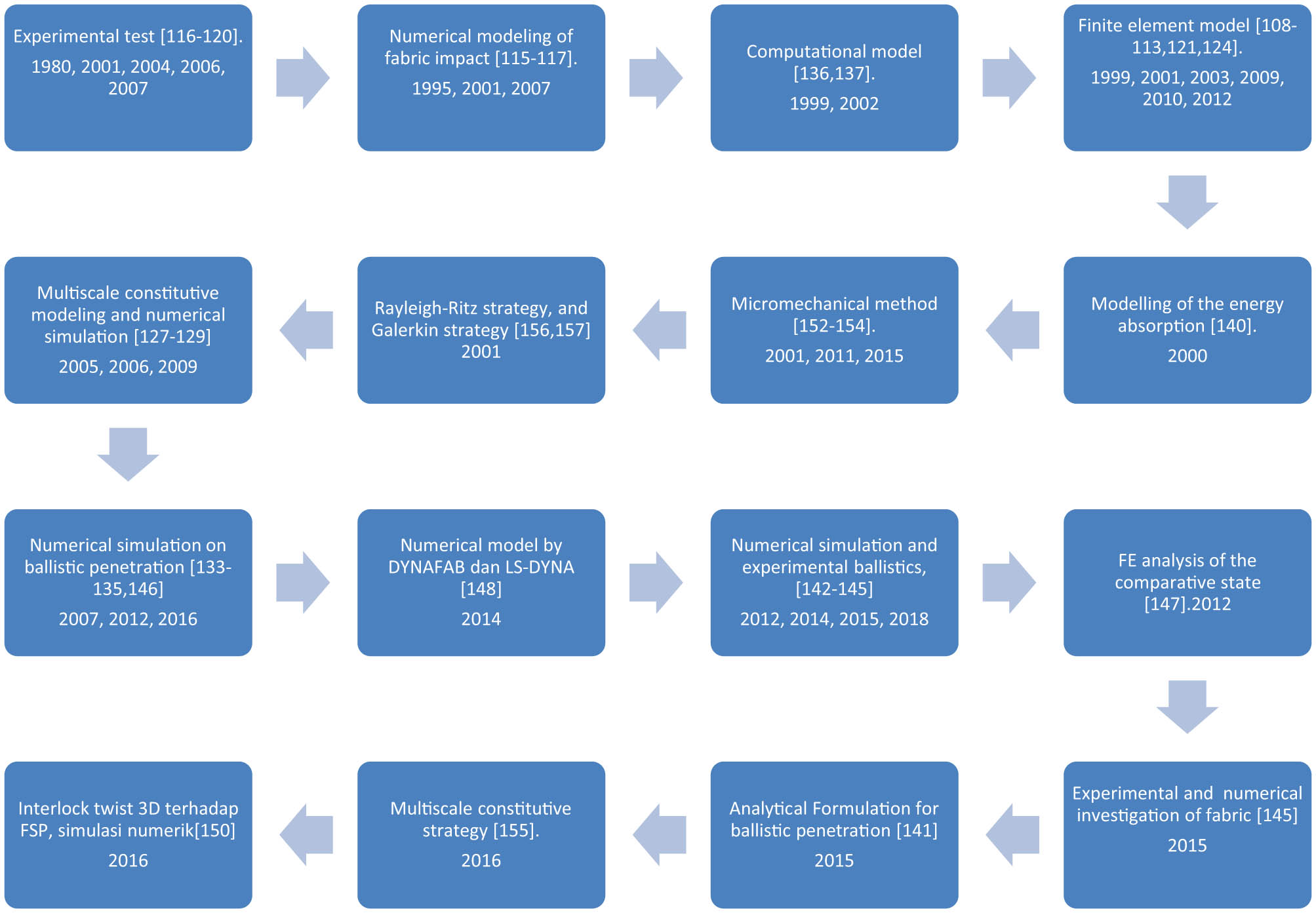
Milestones modeling experimental, numerical, computational, and mix method.
5 Milestones of technical apparatus for ballistic performance measurement
Since the beginning of human history, competition in the development of weapons and means of defense has continued. As new weapons were developed, corresponding armor was also developed as a defense response [168]. Today, the development of lightweight defenses against small-caliber projectiles is becoming increasingly crucial as horizontal and urban conflicts require high mobility. Antimaterial ammunition projectiles can penetrate steel armor materials used in military vehicles. This capability comes from the hard steel core of the projectile, which increases its penetration capability compared to nonmaterial munitions. The interaction between small-caliber projectiles and armored steel plates falls within the domain of ballistics science [169].
Ballistics is the science of mechanics mainly concerned with the projectile's acceleration in the gun barrel, the behavior of the projectile at the end of the barrel and while on the trajectory, and its effect on the target. It is mainly separated into three branches: interior, exterior, and terminal ballistics. This research focuses more on terminal ballistics, a branch of ballistics that studies the interaction between projectiles and target materials [170].
Terminal ballistic research is an exciting topic because it is the meeting point between combat power and defense technology. However, the study of terminal ballistics is constrained by high costs and a long time taken to produce valid data. To overcome this, some researchers use methods such as analytics to shorten the time and save research costs. In addition, the data generated can be used as reference data and validation of experimental results. The armor material resists the projectile in terminal ballistics by absorbing its kinetic energy. With the results from the experiment, analytical methods can be developed to determine the energy required for the projectile to penetrate and predict the ballistic limit velocity and residual velocity results of the projectile after impact. The use of experimental data is required as a reference to use the conditions under which the projectile is capable of perforating the armor material. With these data, analytical calculations are carried out with impact velocity variables until data are obtained where the residual velocity of the projectile is not formed. The use of cal. 12.7 mm is based on its ability to penetrate steel materials used as protection for combat vehicles and defense buildings.
In addition to combat vehicle applications, research related to ballistic terminals can also be carried out on projectile design engineering in the face of body armor materials. Current body armor materials that continue to develop with the use of ceramic and composite materials require the use of munitions that have a higher energy density so that they can penetrate [171]. In the previous research, an analytical study was conducted to calculate the energy absorbed by the target material with variable impact angles and the use of hybrid composites. Based on the law of conservation of energy, the total energy of the projectile is equal to the energy absorbed in the perforation and the residual kinetic energy of the projectile. The residual velocity of the projectile is used to find the energy absorbed in the perforation [172]. To make it easier to understand the concept of ballistic testing based on the development of the times, please see the basis of testing in Figures 37 and 38.
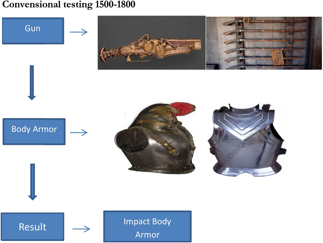
Base of conventional testing.
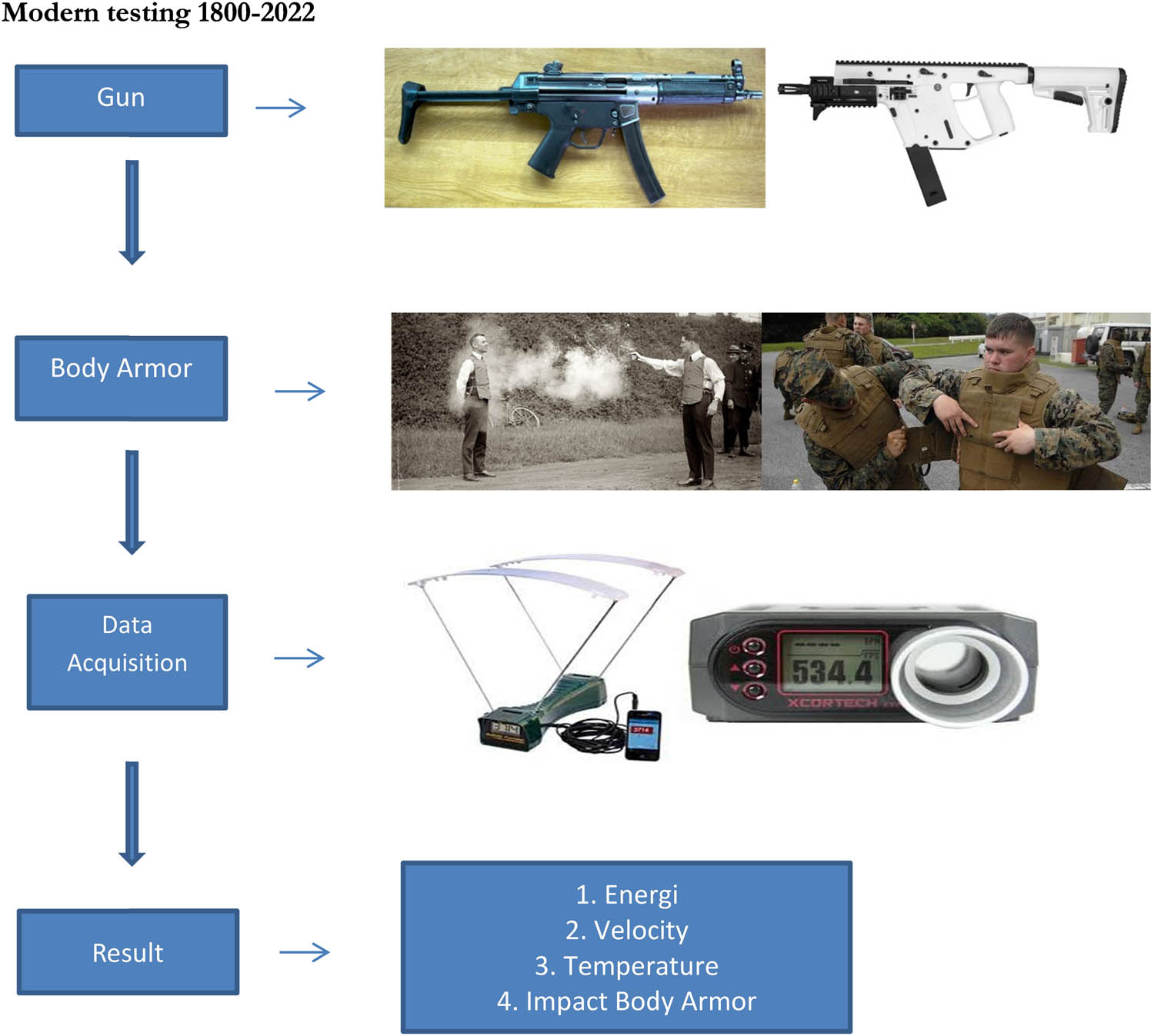
Base of modern testing.
Figure 37 only shows a general description, but actually, there are many variations that have been performed in research to obtain valid data. If we want to compare the process, it will undoubtedly be very different from year to year. On the basis of Figure 38, we can conclude that there are differences in results. The period 1800–2022 has ballistic velocity data, projectile temperature data, ballistic energy data, and impact ballistics. In 1500–1,800 we can only take the impact ballistic results, and the difference is from 1800–2022. Therefore, several test designs are shown in Figures 39–45. Mubashir et al. conducted research in 2018 using a target in the form of a 38.1 mm thick AA5083-H116 aluminum plate, where a 12.7 mm AP tracer bullet was fired toward the target plate from a distance of 300 m and measured using a chronograph [169].
![Figure 39
Schematic representation of the experimental setups with base armor plate and perforated armor plate. The illustration is drawn based on data presented in [169].](/document/doi/10.1515/cls-2022-0200/asset/graphic/j_cls-2022-0200_fig_039.jpg)
Schematic representation of the experimental setups with base armor plate and perforated armor plate. The illustration is drawn based on data presented in [169].
![Figure 40
Schematic exploded view of the ballistic experimental setup [173].](/document/doi/10.1515/cls-2022-0200/asset/graphic/j_cls-2022-0200_fig_040.jpg)
Schematic exploded view of the ballistic experimental setup [173].
![Figure 41
Illustration of the experimental setup used for the high-velocity impact tests [174].](/document/doi/10.1515/cls-2022-0200/asset/graphic/j_cls-2022-0200_fig_041.jpg)
Illustration of the experimental setup used for the high-velocity impact tests [174].
![Figure 42
Schematic illustration of the test fixture. The illustration is drawn based on data presented in [175].](/document/doi/10.1515/cls-2022-0200/asset/graphic/j_cls-2022-0200_fig_042.jpg)
Schematic illustration of the test fixture. The illustration is drawn based on data presented in [175].
![Figure 43
Firing arrangement equipment [176].](/document/doi/10.1515/cls-2022-0200/asset/graphic/j_cls-2022-0200_fig_043.jpg)
Firing arrangement equipment [176].
![Figure 44
Schematic diagram of ballistic test [177].](/document/doi/10.1515/cls-2022-0200/asset/graphic/j_cls-2022-0200_fig_044.jpg)
Schematic diagram of ballistic test [177].
![Figure 45
Schematic diagram of testing apparatus in STRIDE, Batu Arang [178].](/document/doi/10.1515/cls-2022-0200/asset/graphic/j_cls-2022-0200_fig_045.jpg)
Schematic diagram of testing apparatus in STRIDE, Batu Arang [178].
The overall experimental setup is shown in Figure 39, where a 12.7 mm AP tracer bullet was fired toward the target plates from a distance of 300 m. The two configurations of the target plates included: (i) base armor plate and (ii) perforated armor plate in combination with a base armor plate. The target plates were fixed in a rigid fixture. In the multiple armor plate configuration, the base and the perforated armor plates were separated by 110 mm long sleeves, as shown in Figure 39. The velocity of the projectiles was measured by a SuperChrono acoustic chronograph manufactured by Steinert Sensing Systems, Norway. The chronograph was placed in the path of the projectile at 2 m from the firing point. The 12.7 mm AP tracer projectiles were fired on the single- and multiple-level armors. These bullets had an AP core made of hardened steel. However, part of the tracer bullet core is used for filling a small amount of pyrotechnic charge. The pyrotechnic charge burns brightly upon impact with the target [169].
Luza et al. conducted ballistic test research at the Brazilian army's firing range facility, CAEX, on the Marambaia peninsula in Rio de Janeiro in 2015. All tests, 10 for each type of MAS target, were carried out according to the NIJ 0101.06 standard using 7.62 mm × 51 mm NATO military ammunition (7.62 mm for short) with a 9.7 g projectile propelled from a gun barrel. To make it easier to get a sketch in our mind, it is shown in Figure 40.
Figure 40 shows, schematically, the exploded view of the ballistic test setup. A dashed straight line indicates the projectile trajectory. A steel frame was used to position the target, which was held by spring clips. The gun, located 15 m from the target, was sighted in its center with a laser beam. The exact velocities of the projectile at two moments, i.e., leaving the gun and immediately before impacting the MAS target, were measured using an optical barrier (Figure 40) and a model SL-52 OP Weibel fixed-head Doppler radar system. Tests in which the target was perforated allowed the residual velocity of the outcoming projectile to be measured. After the ballistic test, fractured samples of each MAS component were analyzed by scanning electron microscopy and operating with secondary electrons at 20 kV [173].
Mora et al. conducted ballistic test research using cartridges that propel projectiles onto composite specimens. Two chronograph units were placed in front of and behind the target holding unit to record the impact and residual velocities of the projectiles, respectively. The experimental setup is shown in Figure 41.
Based on Figure 41, the 150 × 150 mm2 composite plates were clamped to the target holder. Following the Level III NIJ standard, the tests were conducted using 7.62 × 51 mm2 projectiles at an impact velocity of 847 ± 9.1 m/s and an angle of 90° to the specimen with one shot at the center. The projectiles were measured to have a diameter of 7.79 mm and a mass of 9.65 g [174].
In 2006, Cameron et al. conducted an antiballistic specimen test study involving BABT using a 7.62 mm test bullet (7.62 ball round – 9.72 g) and a hard body armor selected for high deformation with a low probability of penetration for bullet velocities of approximately 670–800 m/s. The main test components were based on a head support fixture designed and manufactured by the Center for Applied Biomechanics (University of Virginia, USA), as shown in Figure 42.
Based on Figure 42, the fixture was designed for use with cadaveric subjects. A sabot was used with a smooth bore barrel (sabot mass = 1 g). No bullet instability was seen in the approximately 35 cm flight to impact. The incoming round velocity was measured using an inductive technique and video analysis [175]. Pîrvu et al. carried out the testing of the realized protection packages to evaluate their resistance to the 9 mm FMJ bullet was discussed in 2021, taking into account the resistance to penetration through the depth of the trace left in the support material (ballistic clay), namely, the backface signature. The following steps are performed when personal testing armor and parts of the experimental setup are shown in Figure 43.
Based on Figure 43, test equipment is positioned in the clamping support at a distance imposed for each piece of equipment from the mouth of the barrel; the types of weapons and ammunition required for levels II and IIA are verified. The bullet speed measurement system is positioned, starting with the distance of 2 m from the mouth of the barrel, so that the frames of the system are in planes perpendicular to the firing direction; the distance between the frames of the system is 0.5 m, and the distances are measured with an accuracy of 1 mm; firing is executed on the test package [176].
In 2020, Kai-Kuang et al. experimented with a ballistic-resistant ceramic composite target plate mainly consisting of silicon SiC ceramic and a Dyneema (unidirectional structure) fiber backplate. +e ceramic plate was hexagonal with side lengths of 60 mm each, fabricated by sintering SiC ceramic powder under atmospheric pressure at a temperature of 2,050°C. A 200 mm × 200 mm piece of Dyneema fabric was cut and hot pressed into the plate at a temperature of 115°C. +e ceramic and fiber plates were then bound together using epoxy resin and compressed under a 10 kg weight for 24 h to ensure they were firmly joined. Figure 44 shows a schematic diagram of the ballistic experiments.
Based on Figure 44, the study conducted a ballistic test in accordance with the NIJ IV standard, using 0.30″ AP ammunitions, with the amount of gunpowder adjusted to achieve an initial velocity of 868 ± 15 m/s. Photoelectric screens were used to measure the velocity of the bullet, whereby two screens were placed 1 m apart to separately measure the initial and residual velocities of the bullet by transmitting the photoelectric signals to the oscilloscope. +e smallest measured scale was 10−6 s [177]. In 2016, Hani et al. conducted samples tested at the Science and Technology Research Institute of Defense (STRIDE), Batu Arang, Selangor, for high-velocity impact tests. The assessment involved determining the ballistic limit, damage mode, and blunt trauma deformation. The test was conducted in accordance with NIJ Standard 0101.04 [178] level IIA with FMJ RN 8.0 g of 9 mm caliber. Figure 45 shows a schematic diagram of the ballistic experiments.
Based on the schematic diagram of the testing equipment in Figure 45, many tools are used to perform this test, ranging from chronographs, telescope cameras, radar, and others. The samples to be tested were cut into dimensions of 310 × 205 mm and thicknesses in the range of 7–9 mm for one composite panel (each containing four layers of woven coir laminate/Kevlar). They were then stacked into three sets of panels (12 layers of woven laminated coir/Kevlar). The ballistic impact was performed using the muzzle of a high-velocity impact rifle [178].
Based on the NIJ Standard, pistol-type weapons (handguns) and armor panels are placed at a distance of 5.0 ± 1.0 m from the gun's muzzle, whereas for rifles, the armor panel is placed at a distance of 15.0 ± 1.0 m from the weapon's muzzle. It is possible to make adjustments or distance tolerances that are not more than 4 m for each test to avoid deviations. For tests using rifle-type weapons, if the test distance is less than 14 m, the deviation can be accepted with a 50-meter angular distance from the target. The support material must be strong and able to remain in a standing position to avoid shifting due to shock during the firing process. Due to shock during the firing process, the speed-measuring device was placed at a distance of 2.5 ± 0.025 m from the front of the supporting material. For the firing angle itself, the placement is placed in the center, with a distance of 2.5 + 0.025 m/−0.190 m from the front of the backing material. Some of the studies presented show that there are tests that do not follow NIJ standards. We predict that limitations in equipment, testing sites, or weather may prevent the research from following NIJ standards.
5.1 Projectile momentum and energy
The generally recognized determinants of the wounding intensity of a projectile are the velocity and mass of the shot, along these lines, its momentum. The latter legitimately corresponds to a measure of the energy transferred into the tissue by the shot during its penetration through the tissue [179]. Some investigations believe it to be the most significant parameter for causing tissue damage [180]; however, different strategies can affect the potential for injury. On the other hand, momentum is a significant parameter that can be used to assess the wounding ability of a shot but is revealed to estimate the wounding potential only slightly [181]. The energy delivered in a shot depends on the size of the explosive material touched to fire the projectile and the distance from the gun gag to the tissue. A shot powered near the tissue will deliver extra energy to the tissue compared to a shot that invests much energy in traveling before cooperating with the tissue; for example, the shot has lost power during its trajectory [182]. A shot can dissipate a certain amount of its dynamic energy if it goes straight through the tissue and exits from the opposite end of the body. In addition, a slug that stops inside the body will transmit all its energy to the organs/tissue of the body. A shot intended to effect a collision would be a state of fire that would transfer its energy to the tissues and would undoubtedly settle inside the body’s tissue. In contrast, a shot intended to remain perfect during its penetration through the body then leaves the body holding most of its energy and continues its trajectory [183].
Shots are classified according to their low or high velocity [183]. However, the meaning of the two classes changes between publications. Bellamy and Zajtchuk [184] characterized high velocity as speeds exceeding 600 m/s, while Rozen and Dudkiewicz [180] describe high-velocity levels as more prominent than the speed of sound in the air medium (e1100 ft/s or 335 m/s). The velocity range of shots fired from military rifles is 700–950 m/s, while pistols range from 250 to 370 m/s [185]. Utilizing the bullet's velocity, rifles are usually considered low-velocity weapons [186].
Nonetheless, the latter weapons cause significant damage to joints, bones, and soft tissue, involving blood vessels and structures due to the dispersal of shot pellets [187]. These results may indicate that both low- and high-velocity weapons severely damage body organs/tissues. The use of projectile strike velocity as the sole indication of the extent and intensity of injury may be misleading [188]. For example, a high-caliber shot with a large mass, despite traveling at a lower velocity, still produces massive tissue damage by producing a permanent cavity, i.e., the bullet damages the tissue.
5.2 Milestone of bullet velocity testing
One of the efforts to test the ballistics and quality of firearms is to calculate muzzle velocity. To calculate the velocity of a weapon projectile, a special tool called a chronometer is required. In the past, we needed a tool with large dimensions, which, of course, took up space and was impractical, but now we can use a very practical tool that can be carried anywhere easily. To better understand the historical development of ballistic measuring tools, see Figure 46.
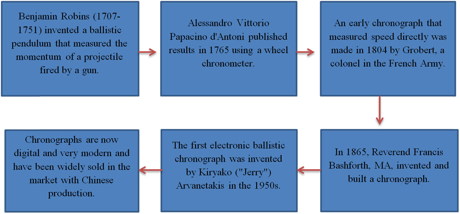
Chronograph tool development history.
Benjamin Robins (1707–1751) invented the ballistic pendulum, which measured the momentum of a projectile fired using a gun. Dividing the momentum by the mass of the projectile gives the velocity. Robbins published his results as New Principles of Gunnery in 1742 [189,190]. A ballistic pendulum can only take one measurement per shot because the device catches the projectile [191]. The accuracy of the gun also limits how far away measurements can be made [192]. Alessandro Vittorio Papacino d'Antoni published results in 1765 using a wheel chronometer. This used a horizontal spinning wheel with vertical paper mounted on the rim. A bullet is fired across the diameter of the wheel so that it pierces the paper on both sides, and the difference in angles, along with the wheel's rotation speed, is used to calculate the velocity of the bullet [193]. An early chronograph that measured speed directly was made in 1804 by Grobert, a colonel in the French Army. It used a rapidly rotating shaft with two disks mounted on it about 13 feet apart. A bullet was fired parallel to the shaft, and the angular displacement of the holes in the two disks, along with the shaft's rotational speed, produced the bullet’s velocity [194].
In 1865, the Reverend Francis Bashforth, MA, who had recently been appointed professor of applied mathematics to the advanced class of artillery officers at Woolwich, began a series of experiments to determine the resistance of air to the motion of spherical and longitudinal projectiles, which he continued from time to time until 1880. As the instruments then used to measure velocity were incapable of providing the time taken by a shot to pass through a series of successive equal spaces, he began his work by inventing and constructing a chronograph to accomplish this object, which was tried at the end of 1865 at Woolwich Marshes, with ten screens and with perfect success. Bashforth screens were made with multiple threads and switches connected in series. A projectile passing through the screen would break one or more threads, the broken threads causing the switch to momentarily (about 20 ms) break the current as the switch arm moved from its weighted position to its unweighted position, and the momentary interruption would be recorded on the graph paper [195].
The first electronic ballistic chronograph was invented by Kiryako (“Jerry”) Arvanetakis in the 1950s. As a consulting engineer under contract by NACA (later NASA), he was asked to find a way to accurately measure the velocity of various projectiles fired at high speed into various engineering materials in anticipation of crewed space flight. His first design was an open rectangular frame of square aluminum tubes with fine copper wire screens at both ends. Disconnecting the first wire starts charging the capacitor, and disconnecting the second wire stops it. Measuring the accumulated voltage and knowing the elapsed time charging rate can be accurately calculated.
5.3 Modern chronograph
Modern chronographs consist of two sensing areas framed by rods topped by a diffused screen or artificial lighting above (or below) the optical sensors that detect the bullet’s trajectory. The time it takes for the bullet to travel the distance between the sensors is measured electronically, from which the velocity is calculated and displayed.
Advanced ballistic chronographs include types that use Doppler radar to measure the bullet in free flight at various distances; others are devices mounted on the end of the barrel, which use magnetic field sensors to measure the bullet’s velocity as it exits the muzzle [196]. The modern chronograph is mainly used for object acceleration and speed measurement. Individual users can use it to measure the design speed of all shooting games, aluminum alloy, stainless steel material, support rod, speed measurement, energy size, and speed energy, see through the record and see the average. This product is used to learn and experience the ability of SCM to process data at high speed and can measure the flying speed of various projectiles, such as table tennis, badminton, bow and arrow, physics acceleration experiments, projectile free fall experiments, NERF toy speed measurement, children's soft toys, and other functions. The core components are an industrial-grade package, stable performance, and minor errors. The tool is used for the speed of 1–999.9 m per projectile, with the accurate speed. It has the advantages of a large effective induction area, convenient use, and high sensitivity. With strong adaptability to ambient light, indoor, and outdoor, it can be used during the day and night. It can store 20 sets of data, with a measurement range of 1–999.9 m/s (FPS range 30–999.9) and the test error of ≤0.5%.
5.4 Sample strength test before conducting ballistic tests
As weapons technology develops, it must also be equipped with defense technology that serves as a counterweight. Technology development must meet the test standards set by the NIJ. Other tests are performed first to shorten the test and to reduce losses due to failed firing tests. Some tests can be carried out, such as a tensile test, hardness test, impact test, and puncture test.
5.4.1 Tensile testing equipment with electricity
This tensile tester with an electricity series tests tension, compression, shearing force, adhesion, peeling force, tear strength, and others of specimens, half products, and finished products in the fields of rubber, plastic, metal, nylon, fabric, paper, aviation, packing, architecture, petrochemical, electric appliance, automobile, and others, which is the primary facility for input quality control, quality control, physical examination, mechanics research, and material development [197].
5.4.2 Hardness tester
The hardness tester is a device that accurately determines the hardness of a material by assessing the impact on its surface through the use of a standardized rounded or pointed indenter made of diamond, carbide, or hard steel; known for its high precision, stable performance, simple operation, and easy to carry. It can be measured in different directions. Leeb's hardness is converted into Brinell, Rockwell, Vickers, shore hardness, and others. Moreover, it can be automatically converted into printed records [198].
5.4.3 Impact tester
An impact tester is a testing tool used to take measurements on a material in accepting the pressure force, which is then measured by the amount of energy needed to break the item with one or more swings. This testing tool was designed to measure a material's durability. Furthermore, it then also aims to ensure that the material or tool does not fail in subsequent use. The material absorbs the energy generated slowly in a standard test, such as tensile and compressive tests. In everyday life, materials absorb energy very quickly from falling objects, blows, collisions, drops, and others. Impact testers are designed to simulate these conditions [199]. The results of this testing can be used as a reference to develop failure criteria due to impact loadings [200–204].
5.4.4 Puncture test
This test is carried out by placing the sample at the bottom of the tool, where the circular area is secured with parameters to keep it hollow (this is performed under existing standards). A pointed probe is used, moving down until the probe pierces the test material. The result of this test is calculated in terms of the maximum force required to puncture the material.
Those are all of the milestones of technical apparatus for ballistic performance measurement, and we can try to use some equipment to measure the ballistic technology, but it is better when starting to test the material with a nonprojectile test because it saves money, because if a firing test must be conducted, the material cannot be replaced, and it is not cheap. Therefore, it is highly recommended to conduct nonprojectile tests before conducting firing tests [205].
6 Concluding remarks
Projectiles fired using a musket are usually lead balls and are accelerated by burning black powder in the gun barrel and behind the projectile. After the battle, the weapon is returned to the base and stored as a standby weapon. Many weapons are impossible to melt because there is a risk of explosion or other complications. Therefore, the weapon is discarded in the sea. For other war equipment such as a buff coat, which enjoyed relatively widespread use among cavalry, buff coats were used as protective clothing during the English and British Civil War. However, its effectiveness as a protective suit is unknown. Buff coats were usually worn over civilian clothing (linen shirts and woolen vests) during the English Civil War because constant use was not expected. Technological development is needed in dealing with conditions involving sharp weapons, firearms, and even intercontinental cruise missiles. This is why antiballistics are needed, such as aramid cloth that can withstand knife cuts, bulletproof material that can withstand projectiles, and iron domes that can detonate missiles. Above the sky before reaching the target. One thing that needs to be emphasized is that the vest does not protect the body from being shot, but using a vest can reduce the risk.
The size of the specimen can also affect the Izod impact test value as it can allow for different amounts of imperfections in the material, which can act as a stress booster and lower the impact energy. Types of impact test specimens include notch configurations such as V-Notch, U-Notch, and Key-Hole Notch, as well as un-notched and ISO (DIN) V-Notch, with impact testing capabilities of sub-size specimens up to size. The impact test is more important to determine the amount of energy the material absorbs during fracture. The classical pendulum impact tester determines the impact energy absorbed by a standard specimen at breaking by measuring the height of the pendulum hammer rise after impact. There are two types of impact tests: pendulum and drop weights. Impact energy measures the work needed to break the test specimen. The models made for the impact of rigid projectiles were also used in the case of the impact of deformable projectiles since no damage to the projectiles was observed by the authors in their experiments, thus following the assumption of negligible deformation of the projectiles.
Significant research efforts were made continuously to improve the ballistic impact function of the available materials and develop advanced ballistic materials along with different mechanical characteristics for several types of technical uses involving body armor systems. The development of materials, such as fiber and ballistic types, performs very well for ballistic purposes and has seen general investigation to meet the need for bulletproof capacity, high quality, and lightweight. Robust, low-density materials are sought after for another era of ballistic protection. Along with the advancement of material-reinforced composites, fiber-based composites also play an increasingly significant role as body materials for military vehicles and aircraft. Likewise, with the situation, the fibers for ballistic protection in this era are mostly aramid and UHMWPE fibers.
A nonexperimental analysis such as an FEA is very useful for engineers performing structural analysis. Many types of FEA are integrated with CAD software today, making the transition between software easier. On the other hand, MATLAB is essential for performing complex numerical analyses that require programming solutions. Meanwhile, Python is a free, open-source language perfect for scientific programming. While suitable for scientific programming, Python is designed for general purposes. Several researchers have promoted and developed numerical models that rely on numerical methods, such as finite difference and FEMs. Furthermore, nonexperimental analysis can easily differentiate the impact behaviors of the fabric on double-nose projectiles, single-nose cones, and flat projectiles. It is also usually revealed that it is tough to truly understand and photograph ballistic impacts using exclusively exploratory, experimental, numerical, or analytical strategies. That is why different authors use a mix of exploratory, numerical, experimental, and explanatory methodologies to obtain better interpretation and practical examination of data during ballistic impact systems.
With the results from the experiment, analytical methods can be developed to determine the energy required for the projectile to penetrate and to predict the ballistic limit velocity and residual velocity results of the projectile after impact. With these data, analytical calculations are carried out with impact velocity variables until data are obtained where the residual velocity of the projectile is not formed. Based on the law of conservation of energy, the total energy of the projectile is equal to the energy absorbed in the perforation and the residual kinetic energy of the projectile. The residual velocity of the projectile is used to find the energy absorbed in the perforation. The generally recognized determinants of the wounding intensity of a projectile are the velocity and mass of the shot, along these lines, its momentum, but the energy delivered in a shot depends on the size of the explosive material touched to fire the projectile and the distance from the gun gag to the tissue. To calculate the velocity of a weapon projectile, a special tool called a chronometer is required, and then the momentum is divided by the mass of the projectile, which gives the velocity. If we already know the strength of the projectile, we can design a self-defense tool. Tool validation is carried out by conducting feasibility testing using other mechanical tools such as impact tests, tensile tests, and other tools. In terms of testing the capabilities of antiballistic technology, it would be beneficial to conduct a software analysis test and then test the material with several nonprojectile tests because it would save money. If directly conducting firing tests on antiballistic technology does not deliver the expected result, the material cannot be repaired, and it will be costly in terms of development and inefficient. Therefore, it is highly recommended to conduct nonprojectile tests before conducting firing tests. Therefore, this article covers the theoretical concept of impact, an experimental approach for ballistic tests on advanced materials, the idealization of ballistic tests in computational mechanic simulation, and milestones of technical apparatus for ballistic performance measurement. These are summarized to serve as a knowledge base and reference for future research development.
Nomenclatures
- A
-
Flow area
- A c
-
Projectile contact area
- d
-
Diameter projectile
- D
-
Caliber density the projectile (lb/in) D = W/d 3
- e
-
Perforation thickness
- E 1
-
Modulus of the first layer
- E r
-
Relaxed Modulus of the viscoelastic material
- E u
-
Unrelaxed Modulus of the viscoelastic material
- f A
-
Frequency tuned by the first layer
- f crit
-
Critical frequency of the viscoelastic layer
-
-
Ultimate compressive strength of concrete
- G
-
- I a
-
a nondimensional Impak factor
- K
-
The concrete penetrability factor.
- I+
-
Positive Impulse
- I−
-
Negative Impulse
- I 0
-
Incident impulse onto the armor
- I t
-
Transmitted impulse from the armor to the protected structure
- L 1
-
Thickness of the first layer
- M
-
Mass of the projectile
- m a
-
Mass of the armor
- M s
-
Mach Number
- m s
-
Mass of the protected structure
- N
-
The projectile shape factor
- P
-
Wave Pressure
- P i
-
Impact pressure per unit contact surface area at time during penetration
- P 0
-
Ambient pressure at ‘t’ = 0
- P (t)
-
Wave pressure at time instant ‘t’
- PtB
-
Transmitted Pressure in Layer ‘B’
- Pi,A
-
Incident Pressure at the interface of Layers ‘A’ and ‘B’
- R 0
-
Explosion length
- R s
-
Distance covered by shock wave after time ‘t’
- rho 1
-
Density of the first layer
- s
-
Scabbing thickness
- t
-
Target thickness
- τ
-
Relaxation time
- V
-
Striking velocity of projectile
- v i
-
Instantaneous projectile velocity at time during penetration
- W
-
Projectile weight
- x
-
Total penetration depth
- x i
-
In the instantaneous penetration depth at timet during penetration
- x p
-
Penetration depth
- Z A
-
Acoustic impedance of material in Layer ‘A’
- Z B
-
Acoustic impedance of material in Layer ‘B’
- σ i
-
Incident compressive stress wave
- σ t
-
Transmitted compressive stress wave
- Δ(μ)
-
Rate of change in momentum
-
Funding information: This work was supported by the RKAT PTNBH Universitas Sebelas Maret - Year 2023, under Research Scheme of “Penelitian Kolaborasi Internasional” (KI-UNS), with Research Grant/Contract No. 228/UN27.22/PT.01.03/2023. The support is gratefully acknowledged by the authors.
-
Author contributions: Fattah Maulana: conceptualization, investigation, formal analysis, validation, methodology, data curation, and writing – original and editing. Aditya Rio Prabowo: supervision, conceptualization, investigation, supervision, writing – original draft, project administration, supervision, writing – original draft, writing – review and editing, and funding acquisition. Ridwan Ridwan: investigation, formal analysis, writing – original draft, writing – review and editing, software, and data curation. Ubaidillah Ubaidillah: supervision, conceptualization, methodology, and visualization. Dody Ariawan: supervision, conceptualization, methodology, and visualization. Jung Min Sohn: conceptualization, methodology, writing – review and editing, funding acquisition, and project administration. Nurul Muhayat: conceptualization, visualization, writing – review and editing, funding acquisition, and project administration. Dominicus Danardono Dwi Prija Tjahjana: conceptualization, writing – review and editing, funding acquisition, and project administration. Quang Thang Do: conceptualization, methodology, writing – review and editing, funding acquisition, and project administration.
-
Conflict of interest: The authors declare no conflicts of interest.
-
Data availability statement: The authors declares that the data supporting the findings of this study are available within the article.
References
[1] Frankel J. War. Britannica. 2022; [cited 2022 Nov 8]. https://www.britannica.com/topic/war.Suche in Google Scholar
[2] Ivanov V, Bozakova N, Balieva GN. Wars as factors causing starvation and malnutrition. J Hyg Eng Des. 2020;31(July):139–44.Suche in Google Scholar
[3] Anon A. Tower of London takes on new name and big project. Arms Collect Newsl. 1985;November 2;S-5.Suche in Google Scholar
[4] Richardson T. The buff-coats at Littlecote House. Can J Arms Collect. 1988;26(1):25–31.Suche in Google Scholar
[5] Richardson T, Rimer G. Littlecote: the english Civil War Armoury. Leeds, UK: Royal Armouries; 2019.Suche in Google Scholar
[6] Dowen K. The seventeenth century buff-coat. J Arrms Armour Soc. 2015;21(5):157–88.Suche in Google Scholar
[7] Parnell G. The artillery train sent to New England in 1664. Man Arms Gun Sword Collect. 2012;34(5):24–32.Suche in Google Scholar
[8] Peachey S. The Soldiers Life in the English Civil War. 1st ed. Bristol, UK: Stuart Press; 2016.Suche in Google Scholar
[9] Foard G. Integrating Documentary and Archaeological Evidence in the Investigation of Battles: A Case Study from Seventeenth-Century England [dissertation]. Norwich: University of East Anglia; 2008.Suche in Google Scholar
[10] Akhavan J. The chemistry of explosives. 2nd ed. Dorchester: Royal Society of Chemistry; 2006.Suche in Google Scholar
[11] Andrade T. The gunpowder age: China. Military Innovation, and the Rise of the West in World History. Princeton (NJ), USA: Princeton University Press; 2016.10.2307/j.ctvc77j74Suche in Google Scholar
[12] Ágoston G. Military transformation in the Ottoman Empire and Russia, 1500–1800. Kritika. 2011;12(2):281–319.10.1353/kri.2011.0018Suche in Google Scholar
[13] Needham J. Science and civilization in China. Cambridge, UK: Cambridge University Press; 1986.Suche in Google Scholar
[14] Sipri. Global arms industry: US companies dominate the Top 100; Russian arms industry moves to second place. Stock Int Peace Res Inst; 2018 [cited 2022 Nov 8]. https://www.sipri.org/media/press-release/2018/global-arms-industry-us-companies-dominate-top-100-russian-arms-industry-moves-second-place/.Suche in Google Scholar
[15] Sipri. The SIPRI top 100 arms-producing and military services companies, 2018. Stockholm, Sweden: SIPRI; 2019.Suche in Google Scholar
[16] Wilkinson I. Chemical weapon munitions dumped at sea: An interactive map. James Martin Cent Nonproliferation Stud; 2017 [cited 2022 Nov 8]. https://nonproliferation.org/chemical-weapon-munitions-dumped-at-sea.Suche in Google Scholar
[17] Curry A, Magazine H. chemical weapons dumped in the Ocean After World War II Could Threaten Waters Worldwide. Smithson Mag; 2016 [cited 2022 Nov 8]. https://www.smithsonianmag.com/science-nature/decaying-weapons-world-war-II-threaten-waters-worldwide-180961046/.Suche in Google Scholar
[18] Executive M. Military ordinance dumped in Gulf of Mexico. Marit Exec LLC; 2015 [cited 2022 Nov 8]. https://www.maritime-executive.com/article/military-ordinance-dumped-in-gulf-of-mexico.Suche in Google Scholar
[19] Herwick III EB. Explosive beach objects-- just another example of massachusetts’ charm. GBH; 2015 [cited 2022 Nov 8]. https://www.wgbh.org/news/post/explosive-beach-objects-just-another-example-massachusetts-charm.Suche in Google Scholar
[20] Evans DL, Bond PJ, Bement AL. Office of law enforcement standards. Gaithersburg (MD), USA: National Institute of Standards and Technology; 2003.Suche in Google Scholar
[21] Christiansen EL, Crews JL. NASA JSC Hypervelocity Impact Test (HVIT). Washington DC, USA: NASA; 1992.Suche in Google Scholar
[22] Frankel Lyons/UTC Aerospace Systems. ISS soyuz OM steel BL's HVI report. Washington DC, USA: NASA; July 2013.Suche in Google Scholar
[23] Wu XJ, Gorham DA. Stress equilibrium in the split Hopkinson pressure bar test. J Phys IV. 1997;7(3):91–6.10.1051/jp4:1997318Suche in Google Scholar
[24] Chen X, Wu S, Zhou J. Quantification of dynamic tensile behavior of cement-based materials. Constr Build Mater. 2014;51:15–23.10.1016/j.conbuildmat.2013.10.039Suche in Google Scholar
[25] Frew DJ, Forrestal MJ, Chen W. Pulse shaping techniques for testing elastic-plastic materials with a split Hopkinson pressure bar. Exp Mech. 2005;45(2):186–95.10.1007/BF02428192Suche in Google Scholar
[26] Zhou XQ, Hao H. Modelling of compressive behaviour of concrete-like materials at high strain rate. Int J Solids Struct. 2008;45(17):4648–61.10.1016/j.ijsolstr.2008.04.002Suche in Google Scholar
[27] Zhai C, Chen L, Fang Q, Chen W, Jiang X. Experimental study of strain rate effects on normal weight concrete after exposure to elevated temperature. Mater Struct Constr. 2017;50(1):1–11.10.1617/s11527-016-0879-4Suche in Google Scholar
[28] Hassan M, Wille K. Experimental impact analysis on ultra-high performance concrete (UHPC) for achieving stress equilibrium (SE) and constant strain rate (CSR) in Split Hopkinson pressure bar (SHPB) using pulse shaping technique. Constr Build Mater. 2017;144:747–57.10.1016/j.conbuildmat.2017.03.185Suche in Google Scholar
[29] Dilger WH, Koch R, Kowalczyk R. Ductility of plain and confined concrete under different strain rates. J Proc. 1984;81(1):73–81.10.14359/10649Suche in Google Scholar
[30] Bischoff PH, Perry SH. Compressive behaviour of concrete at high strain rates. Mater Struct. 1991;24:425–50.10.1007/BF02472016Suche in Google Scholar
[31] Mali S, Pachpande T, Kothrud AJ. Effect of rate of loading on compressive strength of concrete. Int J Innov Emerg Res Eng. 2015;2:20–5.Suche in Google Scholar
[32] Sun JS, Ma LJ, Dou YM, Zhou J. Effect of strain rate on the compressive mechanical properties of concrete. Adv Mater Res. 2012;450–451:244–7.10.4028/www.scientific.net/AMR.450-451.244Suche in Google Scholar
[33] Su Y, Li J, Wu C, Wu P, Li ZX. Effects of steel fibres on dynamic strength of UHPC. Constr Build Mater. 2016;114:708–18.10.1016/j.conbuildmat.2016.04.007Suche in Google Scholar
[34] Li QM, Reid SR, Wen HM, Telford AR. Local impact effects of hard missiles on concrete targets. Int J Impact Eng. 2005;32(1–4):224–84.10.1016/j.ijimpeng.2005.04.005Suche in Google Scholar
[35] Kennedy RP. A review of procedures for the analysis and design of concrete structures to resist missile impact effects. Nucl Eng Des. 1976;37(2):183–203.10.1016/0029-5493(76)90015-7Suche in Google Scholar
[36] Chen XW, Li QM. Transition from nondeformable projectile penetration to semihydrodynamic penetration. J Eng Mech. 2004;130(1):123–7.10.1061/(ASCE)0733-9399(2004)130:1(123)Suche in Google Scholar
[37] Kosteski LE, Riera JD, Iturrioz I, Singh RK, Kant T. Assessment of empirical formulas for prediction of the effects of projectile impact on concrete structures. Fatigue Fract Eng Mater Struct. 2015;38(8):948–59.10.1111/ffe.12285Suche in Google Scholar
[38] ACE. Fundamentals of protective design. Washington DC, USA: Army Corps of Engineers; 1946.Suche in Google Scholar
[39] NDRC. Effects of impact and explosions. Washington DC, USA: National Defense Research Committee; 1946.Suche in Google Scholar
[40] Li QM, Chen XW. Dimensionless formulae for penetration depth of concrete target impacted by a non-deformable projectile. Int J Impact Eng. 2003;28(1):93–116.10.1016/S0734-743X(02)00037-4Suche in Google Scholar
[41] Barr P. Guidelines for the design and assessment of concrete structures subjected to impact. Culcheth, UK: UKAEA Safety and Reliability Directorate; 1988.Suche in Google Scholar
[42] Almusallam TH, Siddiqui NA, Iqbal RA, Abbas H. Response of hybrid-fiber reinforced concrete slabs to hard projectile impact. Int J Impact Eng. 2013;58:17–30.10.1016/j.ijimpeng.2013.02.005Suche in Google Scholar
[43] Hwang HJ, Kim S, Kang T. Prediction of Hard Projectile Penetration on Concrete Targets. The 2016 Structures Congress; 2016 28 Aug-1 Sep; Jeju Island, South Korea. p. 1–7.Suche in Google Scholar
[44] Kravanja S, Sovják R. Ultra-high-performance fibre-reinforced concrete under high-velocity projectile impact. Part II. applicability of prediction models. Acta Polytech. 2018;58(6):355–64.10.14311/AP.2018.58.0355Suche in Google Scholar
[45] Kravanja S, Sovják R. Ultra-high-performance fibre-reinforced concrete under high-velocity projectile impact. Part I. experiments. Acta Polytech. 2018;58(4):232–9.10.14311/AP.2018.58.0232Suche in Google Scholar
[46] Rubin MB, Yarin AL. A generalized formula for the penetration depth of a deformable projectile. Int J Impact Eng. 2002;27(4):387–98.10.1016/S0734-743X(01)00061-6Suche in Google Scholar
[47] Abbas H, Almusallam T, Al-Salloum Y, Siddiqui N. Prediction of ejected mass from hybrid-fiber reinforced concrete slabs subjected to impact loads. Procedia Eng. 2017;173:77–84.10.1016/j.proeng.2016.12.035Suche in Google Scholar
[48] Máca P, Sovják R, Konvalinka P. Mix design of UHPFRC and its response to projectile impact. Int J Impact Eng. 2014;63:158–63.10.1016/j.ijimpeng.2013.08.003Suche in Google Scholar
[49] Kneubuehl BP, Coupland RM, Rothschild MA, Thali MJ. Wound Ballistics: Basics and Applications. Berlin, Germany: Springer; 2011.10.1007/978-3-642-20356-5Suche in Google Scholar
[50] Johnson GR, Cook WH. Fracture characteristics of Three Metals Subjected To Various Strains, Strain Rates, Temperatures And Pressures. Eng Fract Mech. 1985;21(1):31–48.10.1016/0013-7944(85)90052-9Suche in Google Scholar
[51] Abtew MA, Boussu F, Bruniaux P, Liu H. Fabrication and mechanical characterization of dry three-dimensional warp interlock para-aramid woven fabrics: Experimental methods toward applications in composite reinforcement and soft body armor. Materials. 2020;13(19):4233.10.3390/ma13194233Suche in Google Scholar PubMed PubMed Central
[52] Johnson GR. Materials characterization for computations involving severe dynamic loading. Proc Army Symp Solid Mech; 1980. p. 62–7.Suche in Google Scholar
[53] Claus J, Santos RAM, Gorbatikh L, Swolfs Y. Effect of matrix and fibre type on the impact resistance of woven composites. Compos Part B Eng. 2020;183:107736.10.1016/j.compositesb.2019.107736Suche in Google Scholar
[54] Bhatnagar A. Lightweight Ballistic Composites. Duxford, UK: Woodhead Publishing; 2006.10.1533/9781845691554Suche in Google Scholar
[55] Termonia Y. Impact Resistance of Woven Fabrics. Text Res J. 2004;74(8):723–9.10.1177/004051750407400811Suche in Google Scholar
[56] Tam DKY, Ruan S, Gao P, Yu T. 10 - High-performance ballistic protection using polymer nanocomposites. In:Advances in Military Textiles and Personal Equipment. Sawston, UK: Woodhead Publishing; 2012.10.1533/9780857095572.2.213Suche in Google Scholar
[57] Pirvu C. Contribution on Experimental and Numerical Study of Ballistic Protection Packages Made of Aramid Fabrics [dissertation]. Galați: Dunarea de Jos University; 2015.Suche in Google Scholar
[58] Bajya M, Majumdar A, Butola BS, Arora S, Bhattacharjee D. Ballistic performance and failure modes of woven and unidirectional fabric based soft armour panels. Compos Struct. 2021;255:112941.10.1016/j.compstruct.2020.112941Suche in Google Scholar
[59] Guo Z, Chen W. A merit parameter to determine the stacking order of heterogeneous diphasic soft armor systems. Compos Struct. 2020;241:112086.10.1016/j.compstruct.2020.112086Suche in Google Scholar
[60] Nunes SG, Scazzosi R, Manes A, Amico SC, de Amorim Júnior WF, Giglio M. Influence of projectile and thickness on the ballistic behavior of aramid composites: Experimental and numerical study. Int J Impact Eng. 2019;132:103307.10.1016/j.ijimpeng.2019.05.021Suche in Google Scholar
[61] Abtew MA, Boussu F, Bruniaux P, Loghin C, Cristian I. Ballistic impact mechanisms – A review on textiles and fibre-reinforced composites impact responses. Compos Struct. 2019;223:110966.10.1016/j.compstruct.2019.110966Suche in Google Scholar
[62] Naik S, Dandagwhal RD, Loharkar PK. A review on various aspects of Kevlar composites used in ballistic applications. Mater Today Proc. 2020;21:1366–74.10.1016/j.matpr.2020.01.176Suche in Google Scholar
[63] Gürgen S. Numerical modeling of fabrics treated with multi-phase shear thickening fluids under high velocity impacts. Thin-Walled Struct. 2020 July;148:106573.10.1016/j.tws.2019.106573Suche in Google Scholar
[64] Yang Y, Zhang X, Chen X, Min S. Numerical study on the effect of Z-warps on the ballistic responses of para-aramid 3d angle-interlock fabrics. Materials. 2021;14(3):1–13.10.3390/ma14030479Suche in Google Scholar PubMed PubMed Central
[65] Chen X, Chaudhry I. Ballistic protection. In:Scott R, editor. Textiles for protection. Cambridge, UK: Woodhead Publishing; 2005.10.1201/9781439823811.ch19Suche in Google Scholar
[66] Saxtorph NM. Warriors and weapons of Early Times. New York (NY), USA: Blandford Press; 1972.Suche in Google Scholar
[67] Sun D. Ballistic performance evaluation of woven fabrics based on experimental and numerical approaches. In: Ad Fibrous Comp Mater for Ball Protec. Duxford, UK: Woodhead Publishing; 2016.10.1016/B978-1-78242-461-1.00014-5Suche in Google Scholar
[68] David NV, Gao XL, Zheng JQ. Ballistic resistant body armor: Contemporary and prospective materials and related protection mechanisms. Appl Mech Rev. 2009;62(5):1–20.10.1115/1.3124644Suche in Google Scholar
[69] Yavaş MO, Ahmet AVCI, Şimşir M, Akdemir A. Ballistic performance of Kevlar49/ UHMW-PEHB26 hybrid layered-composite. Int J Eng Res Dev. 2015;7(4):21–7.10.29137/umagd.379789Suche in Google Scholar
[70] Zee RH, Hsieh CY. Energy absorption processes in fibrous composites. Mater Sci Eng A. 1998;246(1–2):161–8.10.1016/S0921-5093(97)00735-1Suche in Google Scholar
[71] Zhang YD, Wang YL, Huang Y, Wan YZ. Preparation and properties of three-dimensional braided UHMWPE fiber reinforced PMMA composites. J Reinf Plast Compos. 2006;25(15):1601–9.10.1177/0731684406068400Suche in Google Scholar
[72] Tan VBC, Tay TE, Teo WK. Strengthening fabric armour with silica colloidal suspensions. Int J Solids Struct. 2005;42(5–6):1561–76.10.1016/j.ijsolstr.2004.08.013Suche in Google Scholar
[73] Dong Z, Sun CT. Testing and modeling of yarn pull-out in plain woven Kevlar fabrics. Compos A Appl Sci Manuf. 2009;40(12):1863–9.10.1016/j.compositesa.2009.04.019Suche in Google Scholar
[74] Karahan M, Ulcay Y, Eren R, Karahan N, Kaynak G. Investigation into the tensile properties of stitched and unstitched woven aramid/vinyl ester composites. Text Res J. 2010;80(10):880–91.10.1177/0040517509346441Suche in Google Scholar
[75] Carothers JP. Body armor, a historical perspective. USMC CSC; 1988 [cited 17 November 2022]. https://www.globalsecurity.org/military/library/report/1988/CJ2.htm.Suche in Google Scholar
[76] Tam T, Bhatnagar A. High-performance ballistic fibers. In: Bhatnagar A, editor. Lightweight Ballistic Composites: Military and Law-Enforcement Applications. Cambridge, UK: Woodhead Publishing; 2006.10.1201/9781439824436.pt2Suche in Google Scholar
[77] Dunn DR. Ballistic testing of textile materials. In:Wilusz E, editor. Military Textiles. New York (NY), USA: Woodhead Publishing; 2008.10.1201/9781439833247.ch10Suche in Google Scholar
[78] Third NIJ. status report to the attorney general on body armor safety initiative testing and activities. US Dep Justice, Natl Inst Justice; 2005 November. http://ojp.gov/bvpbasi/docs/SupplementII_08_12_05.pdf?popupWindow1/4Y.Suche in Google Scholar
[79] Scott BR. New ballistic products and technologies. In: Bhatnagar A, editor. Cambridge, UK: Woodhead Publishing; 2006.10.1533/9781845691554.2.336Suche in Google Scholar
[80] Jitarașu O. Hybrid composite materials for ballistic protection. A Numer Anal Rev Air Force Acad. 2019;17(2):47–56.10.19062/1842-9238.2019.17.2.6Suche in Google Scholar
[81] Hockenberger AS. The effects of weaving on fibre performance in ballistic fabrics made from high-performance polyethylene fibres. J Text Inst. 1998;89(3):595–604.10.1080/00405009808658646Suche in Google Scholar
[82] Carr DJ. Assessment of UHMWPE composites as candidate materials for UK military helmets. Seventh European Composite Materials Conference; 1996 May 14–16; London UK. Woodhead Publishing, 1996.Suche in Google Scholar
[83] Morye SS, Hine PJ, Duckett RA, Carr DJ, Ward IM. Comparison of the properties of hot compacted gel-spun polyethylene fibre composites with conventional gel-spun polyethylene fibre composites. Compos Part A Appl Sci Manuf. 1999;30(5):649–60.10.1016/S1359-835X(98)00175-4Suche in Google Scholar
[84] Brown JR, Egglestone GT. Ballistic properties of composite materials for personnel protection. Melbourne, Australia: Materials Research Laboratory, DSTO; 1989.Suche in Google Scholar
[85] Hsieh CY, Mount A, Jang BZ, Zee RH. Response of polymer composites to high and low velocity impact. In: Michelove LD, editor. Proceedings of the 22nd International SAMPE Technical Conference; 1990 Nov 6–8; Boston (MA), USA. SAMPE, 1990.Suche in Google Scholar
[86] Lin LC, Bhatnager A, Chang HW Ballistic energy absorption of composites. In: Michelove LD, editor. Proceedings of the 22nd International SAMPE Technical Conference; 1990 Nov 6–8; Boston (MA), USA. SAMPE, 1990.Suche in Google Scholar
[87] Segal CL. High performance organic fibres, fabrics and composites for soft and hard armour applications. In: Carri RL, Poveromo LM, editors. 23rd International SAMPE Technical Conference; 1991 Oct 21–24; Kiamesha Lake (NY), USA. SAMPE, 1991.Suche in Google Scholar
[88] Shephard RG. The use of polymers in personal ballistic protection. London, UK: Polymers in Defence, The Plastics and Rubber Institute; 1987.Suche in Google Scholar
[89] Sharma N, Carr D, Kelly P, Viney C. Modelling and experimental investigation into the ballistic behaviour of an ultra high molecular weight polyethylene / thermoplastic rubber matrix composite. Sci Technol. 1999;1:915.Suche in Google Scholar
[90] Taylor SA, Carr DJ. Post failure analysis of 0°/90°ultra high molecular weight polyethylene composite after ballistic testing. J Microsc. 1999;196(2):249–56.10.1046/j.1365-2818.1999.00632.xSuche in Google Scholar PubMed
[91] Cheeseman BA, Bogetti TA. Ballistic impact into fabric and compliant composite laminates. Compos Struct. 2003;61(1–2):161–73.10.1016/S0263-8223(03)00029-1Suche in Google Scholar
[92] Akdemir A, Candan C, Sa̧hin OS. Effects of production parameters and conditioning upon ballistic characteristics of para aramid light armors. J Compos Mater. 2008;42(19):2051–61.10.1177/0021998308094545Suche in Google Scholar
[93] Goda I, Girardot J. A computational framework for energy absorption and damage assessment of laminated composites under ballistic impact and new insights into target parameters. Aerosp Sci Technol. 2021 August;115:106835.10.1016/j.ast.2021.106835Suche in Google Scholar
[94] Rahimijonoush A, Bayat M. Experimental and numerical studies on the ballistic impact response of titanium sandwich panels with different facesheets thickness ratios. Thin-Walled Struct. 2020;157:107079.10.1016/j.tws.2020.107079Suche in Google Scholar
[95] Chatterjee VA, Saraswat R, Verma SK, Bhattacharjee D, Biswas I, Neogi S. Embodiment of dilatant fluids in fused-double-3D-mat sandwich composite panels and its effect on energy-absorption when subjected to high-velocity ballistic impact. Compos Struct. 2020;249:112588.10.1016/j.compstruct.2020.112588Suche in Google Scholar
[96] Yu S, Yu X, Ao Y, Mei J, Jiang W, Liu J, et al. The impact resistance of composite Y-shaped cores sandwich structure. Thin-Walled Struct. 2021;169:108389.10.1016/j.tws.2021.108389Suche in Google Scholar
[97] Khaire N, Tiwari G, Rathod S, Iqbal MA, Topa A. Perforation and energy dissipation behaviour of honeycomb core cylindrical sandwich shell subjected to conical shape projectile at high velocity impact. Thin-Walled Struct. 2022;171:108724.10.1016/j.tws.2021.108724Suche in Google Scholar
[98] Wu S, Xu Z, Hu C, Zou X, He X. Numerical simulation study of ballistic performance of Al2O3/aramid-carbon hybrid FRP laminate composite structures subject to impact loading. Ceram Int. 2022;48(5):6423–35.10.1016/j.ceramint.2021.11.186Suche in Google Scholar
[99] Yang W, Huang R, Liu J, Liu J, Huang W. Ballistic impact responses and failure mechanism of composite double-arrow auxetic structure. Thin-Walled Struct. 2022 May;174:109087.10.1016/j.tws.2022.109087Suche in Google Scholar
[100] Vescovini A, Balen L, Scazzosi R, da Silva AAX, Amico SC, Giglio M, et al. Numerical investigation on the hybridization effect in inter-ply S2-glass and aramid woven composites subjected to ballistic impacts. Compos Struct. 2021;276:114506.10.1016/j.compstruct.2021.114506Suche in Google Scholar
[101] Mohammad Z, Gupta PK, Baqi A. Experimental and numerical investigations on the behavior of thin metallic plate targets subjected to ballistic impact. Int J Impact Eng. 2020;146:103717.10.1016/j.ijimpeng.2020.103717Suche in Google Scholar
[102] Han J, Shi Y, Ma Q, Vershinin VV, Chen X, Xiao X, et al. Experimental and numerical investigation on the ballistic resistance of 2024-T351 aluminum alloy plates with various thicknesses struck by blunt projectiles. Int J Impact Eng. 2022 May;163:104182.10.1016/j.ijimpeng.2022.104182Suche in Google Scholar
[103] Zaera R. Ballistic impacts on polymer matrix composites, composite armor, personal armor. In: Abrate S, editor. Impact Engineering of Composite Structures. New York (NY), USA: Springer; 2011.10.1007/978-3-7091-0523-8_7Suche in Google Scholar
[104] Christine. Aramid Fibers, trade names Kevlar®, Twaron®, Nomex®, Technora®. Christinedemerchant 2022 [cited 17 November 2022]. https://www.christinedemerchant.com/aramid_characteristics.html.Suche in Google Scholar
[105] Tarfaoui M, Akesbi S. A finite element model of mechanical properties of plain weave. Colloids Surf A Physicochem Eng Asp. 2001;187–188:439–48.10.1016/S0927-7757(01)00611-2Suche in Google Scholar
[106] Teng JG, Chen SF, Hu JL. A finite-volume method for deformation analysis of woven fabrics. Int J Numer Methods Eng. 1999;46(12):2061–98.10.1002/(SICI)1097-0207(19991230)46:12<2061::AID-NME802>3.0.CO;2-QSuche in Google Scholar
[107] Kumar S, Gupta, Singh DS, Sharma I, A. Behavior of kevlar/epoxy composite plates under ballistic impact. J Reinf Plast Compos. 2010;29(13):2048–64.10.1177/0731684409343727Suche in Google Scholar
[108] Simons JW, Erlich DC, Shockey DA. Finite element design model for ballistic response of woven fabrics. 19th International Symposium of Ballistics; 2001 May 7–11; Interlaken, Switzerland.Suche in Google Scholar
[109] D’Amato E. Finite element modeling of textile composites. Compos Struct. 2001;54(4):467–75.10.1016/S0263-8223(01)00119-2Suche in Google Scholar
[110] Lim CT, Shim VPW, Ng YH. Finite-element modeling of the ballistic impact of fabric armor. Int J Impact Eng. 2003;28(1):13–31.10.1016/S0734-743X(02)00031-3Suche in Google Scholar
[111] Kiciński R, Szturomski B, Jurczak W. Determination of material characteristics necessary for modelling of marine structures exposed to small-calibre bullet. J Kones. 2019;26(4):105–11.10.2478/kones-2019-0096Suche in Google Scholar
[112] Kiciński R, Kubit A. Small caliber bulletproof test of Warships’ hulls. Materials. 2020;13(17):1–15.10.3390/ma13173848Suche in Google Scholar PubMed PubMed Central
[113] Tarfaoui M, Akesbi S. Numerical study of the mechanical behaviour of textile structures. Int J Cloth Sci Technol. 2001;13(3):166–75.10.1108/EUM0000000005780Suche in Google Scholar
[114] Novotny WR, Cepuš E, Shahkarami A, Vaziri R, Poursartip A. Numerical investigation of the ballistic efficiency of multi-ply fabric armours during the early stages of impact. Int J Impact Eng. 2007;34(1):71–88.10.1016/j.ijimpeng.2006.07.001Suche in Google Scholar
[115] Zeng XS, Shim VPW, Tan VBC. Influence of boundary conditions on the ballistic performance of high-strength fabric targets. Int J Impact Eng. 2005;32(1–4):631–42.10.1016/j.ijimpeng.2005.06.011Suche in Google Scholar
[116] Roylance D, Wang SS. Penetration mechanics of textile structures. In: Laible R, editor. Ballistic Materials and Penetration Mechanics. Amsterdam, Netherlands: Elsevier Scientific Publishing Company; 1980. p. 273–92.10.1016/B978-0-444-41928-6.50017-XSuche in Google Scholar
[117] Talebi H, Wong SV, Hamouda AMS. Finite element evaluation of projectile nose angle effects in ballistic perforation of high strength fabric. Compos Struct. 2009;87(4):314–20.10.1016/j.compstruct.2008.02.009Suche in Google Scholar
[118] Nilakantan G, Keefe M, Wetzel ED, Bogetti TA, Gillespie JW. Computational modeling of the probabilistic impact response of exible fabrics. Compos Struct. 2011;93(12):3163–74.10.1016/j.compstruct.2011.06.013Suche in Google Scholar
[119] Nilakantan G, Keefe M, Wetzel ED, Bogetti TA, Gillespie JW. Effect of statistical yarn tensile strength on the probabilistic impact response of woven fabrics. Compos Sci Technol. 2012;72(2):320–9.10.1016/j.compscitech.2011.11.021Suche in Google Scholar
[120] Nilakantan G, Wetzel ED, Bogetti TA, Gillespie JW. Finite element analysis of projectile size and shape effects on the probabilistic penetration response of high strength fabrics. Compos Struct. 2012;94(5):1846–54.10.1016/j.compstruct.2011.12.028Suche in Google Scholar
[121] Kawabata S, Niwa M. 4—The finite-deformation theory of plain-weave fabrics. Part II : The uniaxial-deformation theory. J Text Inst. 1973;64(2):47–61.10.1080/00405007308630417Suche in Google Scholar
[122] Kawabata S, Niwa M, Kawai H. 5—The finite-deformation theory of plain-weave fabrics. Part III: The shear-deformation theory. J Text Inst. 1973;64(2):37–41.10.1080/00405007308630418Suche in Google Scholar
[123] Grujicic M, Bell WC, Arakere G, He T, Cheeseman BA. A meso-scale unit-cell based material model for the single-ply flexible-fabric armor. Mater Des. 2009;30(9):3690–704.10.1016/j.matdes.2009.02.008Suche in Google Scholar
[124] King MJ, Jearanaisilawong P, Socrate S. A continuum constitutive model for the mechanical behavior of woven fabrics. Int J Solids Struct. 2005;42(13):3867–96.10.1016/j.ijsolstr.2004.10.030Suche in Google Scholar
[125] Nadler B, Papadopoulos P, Steigmann DJ. Multiscale constitutive modeling and numerical simulation of fabric material. Int J Solids Struct. 2006;43(2):206–21.10.1016/j.ijsolstr.2005.05.020Suche in Google Scholar
[126] Chu Y. Surface Modification to Aramid and UHMWPE Fabrics to Increase Inter-yarn Friction for Improved Ballistic Performance [dissertation]. Manchester: University of Manchester; 2015.Suche in Google Scholar
[127] Shahkarami A, Vaziri R. A continuum shell finite element model for impact simulation of woven fabrics. Int J Impact Eng. 2007;34(1):104–19.10.1016/j.ijimpeng.2006.06.010Suche in Google Scholar
[128] Roylance D, Wilde A, Tocci G. Ballistic impact of textile structures. Text Res J. 1973;43(1):34–41.10.1177/004051757304300105Suche in Google Scholar
[129] Rodríguez Millán M, Moreno CE, Marco M, Santiuste C, Miguélez H. Numerical analysis of the ballistic behaviour of Kevlar® composite under impact of double-nosed stepped cylindrical projectiles. J Reinf Plast Compos. 2016;35(2):124–37.10.1177/0731684415608004Suche in Google Scholar
[130] Riccio A, Zarrelli M, Tessitore N. A numerical model for delamination growth simulation in non-crimp fabric composites. Compos Sci Technol. 2007;67(15–16):3345–59.10.1016/j.compscitech.2007.03.029Suche in Google Scholar
[131] Min S, Chu Y, Chen X. Numerical study on mechanisms of angle-plied panels for ballistic protection. Mater Des. 2016;90:896–905.10.1016/j.matdes.2015.11.019Suche in Google Scholar
[132] Johnson GR, Beissel SR, Cunniff PM. A computational model for fabrics subjected to ballistic impact. 18th International Symposium on Ballistics; 1999 Nov 15–19; San Antonio (TX), USA. Technomic Publishing Company, 1999.Suche in Google Scholar
[133] Tabiei A, Ivanov I. Computational miro-mechanical model of flexible woven fabric for finite element impact simulation. Int J Numer Methods Eng. 2002;53(6):1259–76.10.1002/nme.321Suche in Google Scholar
[134] Lee BL, Walsh TF, Won ST, Patts HM, Song JW, Mayer AH. Penetration failure mechanisms of armor-grade fiber composites under impact. J Compos Mater. 2001;35(18):1605–33.10.1177/002199801772661551Suche in Google Scholar
[135] Naik NK, Shrirao P. Composite structures under ballistic impact. Compos Struct. 2004;66(1–4):579–90.10.1016/j.compstruct.2004.05.006Suche in Google Scholar
[136] Morye SS, Hine PJ, Duckett RA, Carr DJ, Ward IM. Modelling of the energy absorption by polymer composites upon ballistic impact. Compos Sci Technol. 2000;60(14):2631–42.10.1016/S0266-3538(00)00139-1Suche in Google Scholar
[137] Shaktivesh, Nair, Naik NS, NK. Ballistic impact behavior of 2D plain weave fabric targets with multiple layers: Analytical formulation. Int J Damage Mech. 2015;24:116–50.10.1177/1056789514524074Suche in Google Scholar
[138] Mohamadipoor R, Zamani E, Pol MH. Analytical and experimental investigation of ballistic impact on thin laminated composite plate. Int J Appl Mech. 2018;10(2):1850020.10.1142/S1758825118500205Suche in Google Scholar
[139] Sikarwar RS, Velmurugan R, Madhu V. Experimental and analytical study of high velocity impact on Kevlar/Epoxy composite plates. Cent Eur J Eng. 2012;2(4):638–49.10.2478/s13531-012-0029-xSuche in Google Scholar
[140] Chen X, Zhou Y, Wells G. Numerical and experimental investigations into ballistic performance of hybrid fabric panels. Compos B Eng. 2014;58:35–42.10.1016/j.compositesb.2013.10.019Suche in Google Scholar
[141] Kędzierski P, Popławski A, Gieleta R, Morka A, Sławiński G. Experimental and numerical investigation of fabric impact behavior. Compos B Eng. 2015;69:452–9.10.1016/j.compositesb.2014.10.028Suche in Google Scholar
[142] Jia X, Sun B, Gu B. A numerical simulation on ballistic penetration damage of 3D orthogonal woven fabric at microstructure level. Int J Damage Mech. 2012;21(2):237–66.10.1177/1056789510397078Suche in Google Scholar
[143] Haque BZ, Gillespie JW. A combined theoretical-semiempirical penetration model of ballistic penetration of thick section composites. J Thermoplast Compos Mater. 2012;25(5):631–59.10.1177/0892705712450296Suche in Google Scholar
[144] Gilson L, Gallant J, Coghe F, Rabet L. Experimental Ballistic Response and Modeling of Compound Structures Based on Textile Fabrics. J Multifunct Compos. 2015;2(2):105–12.10.12783/issn.2168-4286/2.2/GilsonSuche in Google Scholar
[145] Pandya KS, Kumar CVS, Nair NS, Patil PS, Naik NK. Analytical and experimental studies on ballistic impact behavior of 2D woven fabric composites. Int J Damage Mech. 2014;24(4):1–41.10.1177/1056789514531440Suche in Google Scholar
[146] Ha-Minh C, Imad A, Boussu F, Kanit T. Experimental and numerical investigation of a 3D woven fabric subjected to a ballistic impact. Int J Impact Eng. 2016;88:91–101.10.1016/j.ijimpeng.2015.08.011Suche in Google Scholar
[147] Dunant CF, Scrivener KL. Micro-mechanical modelling of alkali–silica-reaction-induced degradation using the AMIE framework. Cem Concr Res. 2010;40(4):517–25.10.1016/j.cemconres.2009.07.024Suche in Google Scholar
[148] Yang CC, Ngo T, Tran P. Influences of weaving architectures on the impact resistance of multi-layer fabrics. Mater Des. 2015;85:282–95.10.1016/j.matdes.2015.07.014Suche in Google Scholar
[149] Glüge R, Weber M, Bertram A. Comparison of spherical and cubical statistical volume elements with respect to convergence, anisotropy, and localization behavior. Comput Mater Sci. 2012;63:91–104.10.1016/j.commatsci.2012.05.063Suche in Google Scholar
[150] Sheng SZ, Van Hoa S. Three dimensional micro-mechanical modeling of woven fabric composites. J Compos Mater. 2001;35(19):1701–29.10.1177/002199801772661506Suche in Google Scholar
[151] Sihn S, Roy AK. Development of a three-dimensional mixed variational model for woven composites. II. Numerical solution and validation. Int J Solids Struct. 2001;38(34–35):5949–62.10.1016/S0020-7683(00)00405-4Suche in Google Scholar
[152] Pirvu C, Ionescu TF, Deleanu L, Badea S. Simplified simulation of impact bullet-stratified pack for restraining ballistic tests. MATEC Web Conf. 2017;112:06023.10.1051/matecconf/201711206023Suche in Google Scholar
[153] Bəlţətescu O, Axinte M, Barbu G, Manole V. New approach for porous materials obtaining using centrifugal casting. IOP Conf Ser Mater Sci Eng. 2015;95(1):012018.10.1088/1757-899X/95/1/012018Suche in Google Scholar
[154] Duan Y, Keefe M, Bogetti TA, Cheeseman BA. Modeling friction effects on the ballistic impact behavior of a single-ply high-strength fabric. Int J Impact Eng. 2005;31(8):996–1012.10.1016/j.ijimpeng.2004.06.008Suche in Google Scholar
[155] Yang D. Design, Performance and Fit of Fabrics for Female Body Armour [dissertation]. Manchester: University of Manchester; 2011.Suche in Google Scholar
[156] Szturomski B, Grządziela A, Kiciński R. Analysis of the state of stress in the hull of the ship kormoran II loaded with non-contact mine explosion. Solid State Phenom. 2015;236:3–13.10.4028/www.scientific.net/SSP.236.3Suche in Google Scholar
[157] Dhode T, Patil G, Rajkumar E. Impact analysis of side door of a car and bullet proof vest with material “SAM2X5-630” using finite element analysis. IOP Conf Ser Mater Sci Eng. 2017;263(6):062054.10.1088/1757-899X/263/6/062054Suche in Google Scholar
[158] Zochowski P, Bajkowski M, Grygoruk R, Magier M, Burian W, Pyka D, et al. Ballistic impact resistance of bulletproof vest inserts containing printed titanium structures. Metals. 2021;11(2):1–23.10.3390/met11020225Suche in Google Scholar
[159] Chen X, Zhu F, Wells G. An analytical model for ballistic impact on textile based body armour. Compos Part B Eng. 2013;45(1):1508–14.10.1016/j.compositesb.2012.08.005Suche in Google Scholar
[160] Hogg PJ. Composites for Ballistic Applications. London: Queen Mary, University of London; 2003. 2003;March:1–11.Suche in Google Scholar
[161] Pulungan MA, Sutikno S, Sani MSM. Analysis of Bulletproof Vest Made from Fiber Carbon Composite and Hollow Glass Microsphere (HGM) in Absorbing Energy due to Projectile Impact. IOP Conf Ser Mater Sci Eng. 2019;506(1):012001.10.1088/1757-899X/506/1/012001Suche in Google Scholar
[162] Toma D, Niculescu C, Salistean A, Luca D, Popescu G, Popescu A, et al. Improved fit and performance of female bulletproof vests. ICAMS Proc Int Conf Adv Mater Syst. 2016;1–6.10.24264/icams-2016.III.18Suche in Google Scholar
[163] Li J, Yan W, Wang S, Lu D, Mai R. Analysis on injury for light armored vehicle occupant by the after-effect fragments of rifle projectile. J Phys Conf Ser. 2021;1855(1):012011.10.1088/1742-6596/1855/1/012011Suche in Google Scholar
[164] Jahangir M, Iqbal ST, Shahid S, Siddiqui IA, Ulfat I. MATLAB simulation for teaching projectile motion. Adv J Sci Eng. 2020;1(2):59–61.Suche in Google Scholar
[165] Głębocki R, Jacewicz M. Parametric study of guidance of a 160-mm projectile steered with lateral thrusters. Aerospace. 2020;7:61.10.3390/aerospace7050061Suche in Google Scholar
[166] Dater PH, Wong JM. Effects of Barrel Length on Bore Pressure, Projectile Velocity and Sound Measurement. Seattle (WA), USA: Defense Technical Information Center; 2010.Suche in Google Scholar
[167] Chaturvedi E. Numerical investigation of dynamic interaction with projectile and harmonic behaviour for T-finned machine gun barrels. Def Technol. 2020;16(2):460–9.10.1016/j.dt.2019.07.018Suche in Google Scholar
[168] Deniz T. Ballistic Penetration of Hardened Steel plates [dissertation]. Ankara: Middle East Technical University; 2010.Suche in Google Scholar
[169] Mubashar A, Uddin E, Anwar S, Arif N, Waheed Ul Haq S, Chowdhury MAK. Ballistic response of 12.7 mm armour piercing projectile against perforated armour developed from structural steel. Proc Inst Mech Eng Part L J Mater Des Appl. 2019;233(10):1993–2005.10.1177/1464420718808317Suche in Google Scholar
[170] Rosenberg Z, Dekel E. Terminal Ballistics. New York (NY), USA: Springer; 2012.10.1007/978-3-642-25305-8Suche in Google Scholar
[171] Basyir A, Bura RO, Lesmana D. Experimental consideration of projectile density and hardness effect on its penetration ability in alumina target. J Def Acquis Technol. 2019;1(1):9–15.10.33530/jdaat.2019.1.1.9Suche in Google Scholar
[172] Velmurugan R, Sikarwar RS, Gupta NK. Analytical modelling for ballistic perforation of angle-ply and hybrid composite laminates. IMPLAST Conf Soc Exp Mech Inc; 2010. p. 1–12.Suche in Google Scholar
[173] Luz FS, Junior EP, Louro LH, Monteiro SN. Ballistic test of multilayered armor with intermediate epoxy composite reinforced with jute fabric. Mater Res. 2015;18(Suppl 2):170–7.10.1590/1516-1439.358914Suche in Google Scholar
[174] Mora P, Jubsilp C, Bielawski CW, Rimdusit S. Impact response of aramid fabric-reinforced polybenzoxazine/urethane composites containing multiwalled carbon nanotubes used as support panel in hard armor. Polymers. 2021;13(16):2779.10.3390/polym13162779Suche in Google Scholar PubMed PubMed Central
[175] Bass CR, Salzar RS, Lucas SR, Davis M, Donnellan L, Folk B, et al. Injury risk in behind armor blunt thoracic trauma. Int J Occup Saf Erg. 2006;12(4):429–42.10.1080/10803548.2006.11076702Suche in Google Scholar PubMed
[176] Pîrvu C, Deleanu L. Failure investigation of layered LFT SB1plus package after ballistic tests for level IIA. Polymers. 2021;13(17):2912.10.3390/polym13172912Suche in Google Scholar PubMed PubMed Central
[177] Wu KK, Chen YL, Yeh JN, Chen WL, Lin CS. Ballistic impact performance of SiC ceramic-dyneema fiber composite materials. Adv Mater Sci Eng. 2020;2020:9457489.10.1155/2020/9457489Suche in Google Scholar
[178] Hani AA, Azman NS, Ahmad R, Mariatti M, Roslan MN, Marsi N. Ballistic impact response of woven hybrid coir/kevlar laminated composites. MATEC Web Conf. 2016;78:01048.10.1051/matecconf/20167801048Suche in Google Scholar
[179] LaGarde LA. Gunshot injuries - how they are inflicted - their complications and treatment. New York (NY), USA: William Wood and Co; 1916.Suche in Google Scholar
[180] Rozen N, Dudkiewicz I. Wound ballistics and Tissue Damage. Berlin, Germany: Springer; 2011.10.1007/978-3-642-16155-1_2Suche in Google Scholar
[181] Cunningham LL, Haug RH, Ford J. Firearm injuries to the maxillofacial region: An overview of current thoughts regarding demographics, pathophysiology, and management. J Oral Maxillofac Surg. 2003;61(8):932–42.10.1016/S0278-2391(03)00293-3Suche in Google Scholar PubMed
[182] Stefanopoulos PK, Filippakis K, Soupiou OT, Pazarakiotis VC. Wound ballistics of firearm-related injuries-Part 1: Missile characteristics and mechanisms of soft tissue wounding. Int J Oral Maxillofac Surg. 2014;43(12):1445–58.10.1016/j.ijom.2014.07.013Suche in Google Scholar PubMed
[183] Demuth WE. High velocity bullet wounds of the thorax. Am J Surg. 1968;115(5):616–25.10.1016/0002-9610(68)90087-1Suche in Google Scholar PubMed
[184] Bellamy RF, Zajtchuk R. Conventional Warfare: Ballistic, Blast, and Burn Injuries (Textbook of Military Medicine Series on Combat Casualty Care, Part 1, Volume 5). 1st ed. Washington DC, USA: Surgeon General Department of the Army; 1989.Suche in Google Scholar
[185] Chow YY. Wound ballistics: Part 1 – basic science. Hong Kong J Orthop Surg. 2001;5(2):142–7.Suche in Google Scholar
[186] Ordog GJ, Wasserberger J, Balasubramaniam S. Shotgun wound ballistics. J Trauma. 1988;28(5):624–31.10.1097/00005373-198805000-00011Suche in Google Scholar PubMed
[187] Deitch EA, Grimes WR. Experience with 112 shotgun wounds of the extremities. J Trauma. 1984;24(7):600–3.10.1097/00005373-198407000-00009Suche in Google Scholar PubMed
[188] Fackler ML. Wound ballistics: a review of common misconceptions. Jama. 1988;259(18):2730–6.10.1001/jama.259.18.2730Suche in Google Scholar PubMed
[189] Smith J, John F. Chronograph. In:Chisholm H, editor. Encyclopædia Britannica. Vol. 6. Cambridge (MA), USA: Cambridge University Press; 1911.Suche in Google Scholar
[190] Robins B. New principles of gunnery: containing, the determination of the force of gun-powder, and an investigation of the difference in the resisting power of the air to swift and slow motions. Oxford, UK: J. Nourse; 1742.Suche in Google Scholar
[191] Bashforth F. Description of a Chronograph adapted for measuring the varying velocity of a body in motion through the air and for other purposes only one observation on each round. London, UK: Bell and Daldy; 1866.Suche in Google Scholar
[192] Bashforth F. Description of a Chronograph adapted for measuring the varying velocity of a body in motion through the air and for other purposes “Beyond 295 feet the gun was not sufficiently accurate”. London, UK: Bell and Daldy; 1866.Suche in Google Scholar
[193] Vittorio PDA. Esame della polvere dedicato a sua Sacra Reale Maestà da Alessandro Vittorio Papacino D’Antonj. Torino, Italy: Nella Stamperia Reale; 1765.Suche in Google Scholar
[194] Prony. Report of a method of measuring the initial Velocity of Projectiles discharged from Fire-arms, both horizontally and with different Elevations, made to the Physical and Mathematical Class of the National Institute. In: Nicholson W, editor. A J of Nat Phil, Chem and the Arts. Roma, Italy: Università di Roma; 1805.Suche in Google Scholar
[195] Bashforth F. Description of a Chronograph adapted for measuring the varying velocity of a body in motion through the air and for other purposes. London: Bell and Daldy; 1866.Suche in Google Scholar
[196] Justin. 6 Best Shooting Chronographs. OutdoorWorld Rev. 2022 [cited 2022 Dec 25]. https://outdoorworld.reviews/best-shooting-chronograph/.Suche in Google Scholar
[197] Labtestmachines. Sale 4246003 universal tensile strength testing machine for rubber plastic metal nylon. Labtestmachines. [cited 2022 Dec 25]. https://www.labtestmachines.com/sale-4246003-universal-tensile-strength-testing-machine-for-rubber-plastic-metal-nylon.Suche in Google Scholar
[198] Alatuji. Hardness tester. Alatuji. 2022 [cited 2022 Dec 25]. https://alatuji.co.id/product/hardness-tester/.Suche in Google Scholar
[199] Testingindonesia. Charphy impact tester. PT Testindo. 2022 [cited 2022 Dec 25]. https://testingindonesia.co.id/product-category/testing-machine/impact-tester/charphy-impact-tester/.Suche in Google Scholar
[200] Carvalho H, Ridwan R, Sudarno S, Prabowo AR, Bae DM, Huda N. Failure criteria in crashworthiness analysis of ship collision and grounding using fea: milestone and development. Mekanika Maj Ilm Mekanika. 2022;23(1):30–9.10.20961/mekanika.v22i1.70959Suche in Google Scholar
[201] Prabowo AR, Ridwan R, Tuswan T, Imaduddin F. Forecasting the Effects of Failure Criteria in Assessing Ship Structural Damage Modes. Civ Eng J. 2022;8(10):2053–68.10.28991/CEJ-2022-08-10-03Suche in Google Scholar
[202] Prabowo AR, Ridwan R, Tuswan T, Sohn JM, Surojo E, Imaduddin F. Effect of the selected parameters in idealizing material failures under tensile loads: Benchmarks for damage analysis on thin-walled structures. Curved Layer Struct. 2022;9(1):258–85.10.1515/cls-2022-0021Suche in Google Scholar
[203] Prabowo AR, Ridwan R, Muhayat N, Putranto T, Sohn JM. Tensile analysis and assessment of carbon and alloy steels using fe approach as an idealization of material fractures under collision and grounding. Curved Layer Struct. 2020;7(1):188–98.10.1515/cls-2020-0016Suche in Google Scholar
[204] Ridwan R, Nuriana W, Prabowo AR. Energy absorption behaviors of designed metallic square tubes under axial loading: Experiment based benchmarking andfinite element calculation. J Mech Behav Mat. 2022;31(1):443–61.10.1515/jmbm-2022-0052Suche in Google Scholar
[205] Syaiful. 10 Pengujian Menggunakan Alat universal testing machine. PT Testindo. 2020 [cited 2022 Dec 25]. https://testingindonesia.co.id/10-pengujian-menggunakan-alat-universal-testing-machine/.Suche in Google Scholar
© 2023 the author(s), published by De Gruyter
This work is licensed under the Creative Commons Attribution 4.0 International License.
Artikel in diesem Heft
- Research Articles
- Investigation of differential shrinkage stresses in a revolution shell structure due to the evolving parameters of concrete
- Multiphysics analysis for fluid–structure interaction of blood biological flow inside three-dimensional artery
- MD-based study on the deformation process of engineered Ni–Al core–shell nanowires: Toward an understanding underlying deformation mechanisms
- Experimental measurement and numerical predictions of thickness variation and transverse stresses in a concrete ring
- Studying the effect of embedded length strength of concrete and diameter of anchor on shear performance between old and new concrete
- Evaluation of static responses for layered composite arches
- Nonlocal state-space strain gradient wave propagation of magneto thermo piezoelectric functionally graded nanobeam
- Numerical study of the FRP-concrete bond behavior under thermal variations
- Parametric study of retrofitted reinforced concrete columns with steel cages and predicting load distribution and compressive stress in columns using machine learning algorithms
- Application of soft computing in estimating primary crack spacing of reinforced concrete structures
- Identification of crack location in metallic biomaterial cantilever beam subjected to moving load base on central difference approximation
- Numerical investigations of two vibrating cylinders in uniform flow using overset mesh
- Performance analysis on the structure of the bracket mounting for hybrid converter kit: Finite-element approach
- A new finite-element procedure for vibration analysis of FGP sandwich plates resting on Kerr foundation
- Strength analysis of marine biaxial warp-knitted glass fabrics as composite laminations for ship material
- Analysis of a thick cylindrical FGM pressure vessel with variable parameters using thermoelasticity
- Structural function analysis of shear walls in sustainable assembled buildings under finite element model
- In-plane nonlinear postbuckling and buckling analysis of Lee’s frame using absolute nodal coordinate formulation
- Optimization of structural parameters and numerical simulation of stress field of composite crucible based on the indirect coupling method
- Numerical study on crushing damage and energy absorption of multi-cell glass fibre-reinforced composite panel: Application to the crash absorber design of tsunami lifeboat
- Stripped and layered fabrication of minimal surface tectonics using parametric algorithms
- A methodological approach for detecting multiple faults in wind turbine blades based on vibration signals and machine learning
- Influence of the selection of different construction materials on the stress–strain state of the track
- A coupled hygro-elastic 3D model for steady-state analysis of functionally graded plates and shells
- Comparative study of shell element formulations as NLFE parameters to forecast structural crashworthiness
- A size-dependent 3D solution of functionally graded shallow nanoshells
- Special Issue: The 2nd Thematic Symposium - Integrity of Mechanical Structure and Material - Part I
- Correlation between lamina directions and the mechanical characteristics of laminated bamboo composite for ship structure
- Reliability-based assessment of ship hull girder ultimate strength
- Finite element method on topology optimization applied to laminate composite of fuselage structure
- Dynamic response of high-speed craft bottom panels subjected to slamming loadings
- Effect of pitting corrosion position to the strength of ship bottom plate in grounding incident
- Antiballistic material, testing, and procedures of curved-layered objects: A systematic review and current milestone
- Thin-walled cylindrical shells in engineering designs and critical infrastructures: A systematic review based on the loading response
- Laminar Rayleigh–Benard convection in a closed square field with meshless radial basis function method
- Determination of cryogenic temperature loads for finite-element model of LNG bunkering ship under LNG release accident
- Roundness and slenderness effects on the dynamic characteristics of spar-type floating offshore wind turbine