Finite element method on topology optimization applied to laminate composite of fuselage structure
-
Agus Aribowo
 ,
Muhammad Ilham Adhynugraha
,
Muhammad Ilham Adhynugraha

Abstract
This research applies a numerical study of topology optimization of laminate composite structures by using a finite element method (FEM). In this methodology, the plies orientation is excluded from the optimization. The geometry-based optimization from frames of a MALE UAV fuselage structure is presented. The minimum strain energy with an optimization constraint of 20% of weight reduction is used in the objective function. Before the primary analysis, benchmark studies of topology optimization without considering orientations from previously published literature are performed. The convergence studies were taken to acquire the appropriate mesh size in the FEM technique, which utilized a four-noded shell element. The finite element analysis and optimization results showed that the structural design of the newly framed composite fuselage MALE UAV meets the structural strength requirements specified in the airworthiness standard STANAG 4671.
1 Introduction
The use of composite material as the primary structure in aircraft has been increasing in demand due to its strength-to-weight and stiffness-to-weight features. The emerging era of unmanned aerial vehicles (UAVs) also endorses the application of composite material. This recent trend has initiated the idea of replacing the metal structure of an in-house project of medium altitude long endurance (MALE), especially for the wing and fuselage structure. The replacement of the material has the main objective of weight reduction. Besides the replacement of material, an approach of optimization is also carried out focusing on the topology enhancement of the structure of the UAV.
Recently, topology optimization procedures are widely used to find the best-optimum structure that complies with the objective functions to increase fundamental performance. It has been extensively applied to solve different kinds of engineering problems. For the structural platform of a UAV, topological optimization is an effective method to obtain a lightweight structure that still meets the structural strength requirements. This study presents the numerical review of the topology optimization result of the fuselage structure for the MALE class (as shown in Figure 1) with optimal weight reduction at the same time comply with the operating load conditions.
![Figure 1
Indonesian MALE UAV [11].](/document/doi/10.1515/cls-2022-0191/asset/graphic/j_cls-2022-0191_fig_001.jpg)
Indonesian MALE UAV [11].
The efforts to define the mathematical foundation have been studied thoroughly [1,2,3] which with others has pushed the development of modern topology algorithms. In Deaton and Grandhi [4], a survey of topology optimization types is carried out. The study gives the perspective of the benefits and challenges of each towards one another.
Topology optimization has been applied to several aircraft designs [5,6,7,8]. The applied approach has shown significant advantages over a baseline design. Topology optimization is claimed for its ability to handle complex configurations as discussed in the study of Raymer [9], which assures robustness and lightweight feature. The work has been linked with other disciplines including finite element method (FEM) and additive manufacturing. A subset of topology optimization, called conventional energy-based topology optimization, is applied to deal with the design of wing box aircraft ribs [10]. The approach involves the investigation of suitable objective/constraint functions and formulation for handling multiple load cases.
In fuselage structure, topology optimization is also applicable. One of the instances is the optimization of the pre-stiffened bulkhead as reported in the study of Anderson [12] focusing on improving bulkhead structural integrity, reducing mass, and eliminating resonance from ±10% of the engine excitation frequency. However, there are some concerns about topology optimization as a study in the work of Roskam [13] says that due to the sensitivity to optimization parameters, the topology layout is not unique. The complex interactions involved are also one of the challenges to the interpretation of the layout. Finally, the performance of the topology design concept may give no significant improvement as predicted.
This research work is addressed to conduct a numerical approach based on FEM to topology optimized the UAV fuselage structure. The FE analysis was done using ABAQUS FEA [14]. The numerical validation is first conducted on the simple Messerschmitt–Bolkow–Blohm (MBB) beam structure taken from the previously published literature. After the validation process is complete, the UAV actual structure assessment is carried out as the initial structural evaluation basis before the optimization is carried out. Furthermore, the topology optimization stage is carried out with the objective constraint value being the minimum strain energy value. The structural analysis of the fuselage structure covering various operational load cases is also presented to clarify its effect on optimization. In conclusion, the optimization results show a lighter design of fuselage structures.
2 Previous research on numerical optimization
Numerical optimization has significantly improved aeronautical applications by reducing weight, increasing structural stability and efficiency, and leading to lower operational costs [15]. Table 1 gives the review summaries of several studies on optimization to give a comprehensive insight into this research area.
Summary of the review study on numerical optimization
| Author [refs] | Optimization subject | Description | Conclusion |
|---|---|---|---|
| Lee et al. [16] | Layerwise theory for efficient topology optimization of the laminate structure | This research applies a layerwise theory to topologically optimize beam structure | Different optimal shapes are obtained when the rotation angles of all layers are different. The optimal layouts and the optimal angles of plies are depending on the direction of the loads |
| Hu et al. [17] | The topological design of ring structures with a varying number of substructures, outer-to-inner radius ratio, and loading case is investigated | To develop the efficient filament winding trajectory that follows the load transfer path of the composite part | The topological results revealed that the optimal structures were mostly made up of inner and exterior skin, as well as ribs linking the two. The optimized lattice layout differs from the usual composite lattice design when topology optimization is used as a design technique |
| Elvas et al. [18] | The optimization approach is investigated for possible applications in dynamic decoupling and dynamic synthesis | The primary goal is to develop structures to achieve dynamic performance objectives, with a focus on mode synthesis with a target design | The results demonstrate a trade-off in which the MAC limitation effectively eliminates the undesired motion in return for a lower natural frequency |
| Tong et al. [19] | Optimization of the leading-edge wing structure’s topology using symmetric laminated composite plates | The topology optimization minimized the Least square error between deformed and desired shape | Comparing the deformed and desired shape, the complaint wing leading edge with symmetric composite laminate plates can approximately achieve the desired shape |
| Hu and Vambol [20] | Topology optimization of wing rib structure with symmetric laminated composite plates | This article analyzes and estimates the approach for designing wing ribs with symmetric laminated plates and different fiber orientations based on topology optimization | The topology results show that the fiber orientations of laminated plates have a significant influence on topology shapes and stiffness of the structure |
| Eckrich et al. [21] | Fiber placement technologies provide composites with structural topology and path planning | This study combines fiber deployment methods with topology optimization to provide high design flexibility and material efficiency | The generated paths necessitate some manual rework for the design of intersection points and load introduction areas, as well as the incorporation of potential cutting strategies. Nonetheless, the proposed workflow significantly reduces the number of manual design steps |
| Malik et al. [22] | From a certain number of nodes in two-dimensional space, the topology of a super-stable tensegrity structure is determined | This study represents a strategy for determining a topology that methodically underpins a super-stable tensegrity structure. This not only identifies a single topology but also numerous topologies that can all underpin super-stable tensegrity structures from the same collection of nodes | The suggested method differs in that it leads to a connection from a certain number of nodes that assures a super-stable tensegrity structure, which has never been examined in the literature on tensegrity structures |
Lee et al. [16] performed a topology optimization study on T300/5208 carbon epoxy composite on beam structure. The effect of layer orientation was investigated with layerwise theory. However, the example numerical study excluding the layer orientation has also been performed with 40% mass constraint. The results show that the optimal layouts and the optimal angles of plies are depending on the direction of the loads.
Hu et al. [17] utilized the solid isotropic material with penalization (SIMP) interpolation model to do a topology optimization study for composite lattice ring constructions, which are known for their lightweight and high efficiency and have a large appeal in the aviation and aerospace industries. The influence examination of substructure numbers, loading cases, and radius ratios on topologic forms and mechanical performance is investigated.
Elvas et al. [18] effectively applied a computational framework based on the Discrete Material Optimization formulation to free vibration issues in this study, taking into account both frequencies and mode shapes. The optimization is conducted by optimizing each layer of the laminates and fiber orientation of composite laminates.
Tong et al. [19] investigated the feasibility of morphing wings to change the leading-edge wing shape with symmetric laminated composite plates based on topology optimization. The SIMP model and sensitivity filtering technique were used to define glass fiber ply orientation, which can affect the topology structure of the leading-edge wing structures. The volume constraint for wing leading-edge topology optimization cases has been set to 30%. The result of topology optimization shows that the best design of leading-edge wing structure could achieve a desired aerodynamic shape based on fiber-laminated sequences but not mention the best fiber-laminated sequences.
Hu et al. [20] studied topological optimization design methods for aircraft wing ribs with composite plates. For simplicity, the wing rib’s shape is approximated by a rectangular domain and the original loads are approximated by a shear load on each edge. Wing rib’s material used unidirectional AS4/9773 carbon fiber-reinforced epoxy resin as the single-layer material. Comparing the topology results of isotropic materials and specific fiber orientations indicated that composite-laminated plates could change the topology shape significantly depending on layer sequences. As a result, the optimized structure can reduce by 22.3% more weight than the non-optimized structure.
Eckrich et al. [21] described a methodology for designing fiber-reinforced polymer parts using fiber placement technologies that include anisotropic topology optimization and the derivation of placement paths. The anisotropic bidirectional evolutionary structural optimization algorithm includes a dilate sensitivity filter. It is demonstrated that the filter prevents truss structures with widths smaller than the width of the fiber tape and undercuts transverse to the placement plane, which is not possible with fiber placement technologies. As a result, the algorithm generates stiffness-optimized structures that can withstand the specified load case while consuming the least amount of weight. Existing streamline algorithms are combined with a new strategy of clustering the element orientations to improve the parallelism of adjacent streamlines to derive 2D and 2.5D placement paths.
Malik et al. [22] performed a study that provides a method for generating several super-stable tensegrity structures in two dimensions for a given collection of nodes. The method begins with the identification of basic topologies that lead to super-stable fundamental tensegrities, which are then merged to generate a larger super-stable tensegrity. With examples, the notion of combining small super-stable tensegrities to create larger super-stable tensegrities is established. This method’s advantage would be in achieving several super-stable tensegrities for a large number of nodes, which would be useful in simulating varied morphologies and might be employed in robotics.
3 Methodology
In this section, the framework for topology optimization is carefully reviewed. The governing equation of the general topology problem was considered the foundation for this study. Topology optimization was used to obtain the most efficient structural layout. The proposed iterative solution is shown in this consecutive section. The variable such as load simplification was also constructed following the rule’s compliance of STANAG 4671.
3.1 Problem formulation
In general topology optimization problem, an objective function F is set, which is subject to a volume constraint
subject to
where the state field
Eq. (1) can be approached in two possible ways. The first is a Lagrangian approach which is known for its boundary following mesh, while the latter formulation is the Eulerian approach with its fixed mesh. Both approaches have been studied thoroughly in the study of Tong et al. [19] pointing out a concern in the lack of their solutions. In Lagrangian, generating more holes for optimization solutions may jeopardize the object function. In Eulerian, the increase in several constraints may develop similar hole problems.
Another issue is related to the discrete value of the density variable (0 or 1) prompting difficulties in finding solutions, particularly for the Eulerian method. This issue can be tackled with efficient gradient-based optimization algorithms [20]. The problem can be further seen as a continuous topology optimization problem. The algorithm itself is designed to ensure convergence within a reasonable number of iterations. In this new paradigm, the problem can be written as follows:
subject to
where
ρ
denotes the design variable vector of length N. Also, the part
An issue of checkerboard problems still may be encountered, which refer to patches of alternating black and white elements as a result of bad finite element modeling but are favored by the unrestricted optimization process. The checkerboards may be avoided by the use of higher-order elements, or they are taken care of by all the restriction methods that ensure mesh independence [21].
On the condition that the structural constraints are met, the objective function of topology optimization minimizes the structural strain energy. Increasing the structure’s stiffness will lower the structural strain energy. Giving each finite element unit density using design variables will enable this concept. Strain energy (U) formulation can be stated as follows:
For instance, when calculating the maximum static structural stiffness with volume limitations, the maximum structural stiffness entails determining the minimal statistical strain energy for a given load, which translates to determining the minimum compliance.
3.2 Topology optimization framework
Figure 2 shows the flow chart of the proposed optimization method. The whole process is divided into three steps. The first stage is the process of evaluating the structure using FEM based on the structural model before the optimization process is carried out.

Work flow on numerical topology optimization.
The second stage is the optimization process which begins with the extraction of the frame structure from the complete global finite element method (GFEM) model. After that, the design response is determined using the parameter values for strain energy and mass weight.
In the optimization process, constraints are also given by providing the optimum model with a minimum limit value of 0.5% of the original mass weight. If the initial model cannot meet the constraints, then the constraints are adjusted. After that, the optimization process can be run by giving the command a limit of 50 design cycles. It should be noted that topology optimization achieves convergence values in the range of 25–40 design cycles. The optimization process stops until the minimum strain value is obtained until it converges. Finally, the structural assessment phase was carried out again by incorporating several optimized frames into a complete airframe structure.
3.3 MALE UAV load generation according to STANAG 4671
One of the critical inputs in the optimization process is the aircraft load analysis. The design, requirements, and objectives (DRO) govern everything related to the product development process, and all certification requirements are specified in the DRO. Subpart C of STANAG 4671 specifies almost all of the requirements for MALE UAV load. The load on the aircraft is divided into flight load and ground load. Flight load includes any load that occurs during airborne operations, while ground load includes any load that occurs during the take-off and landing phases.
All external loads acting on the aircraft must undergo analysis. STANAG 4671 Subpart C specifies the probability of any load that must be taken into account. The aircraft load must be analyzed using the GFEM. The output of the GFEM process is a load at the component level, which is stated in the nodal load. The scheme of aircraft load generation is shown in Figure 3.

Aircraft load generation diagram.
Performing an identification of the potential loads that occur on the aircraft is crucial to obtain the appropriate aircraft load. A weight and balance analysis of the aircraft is an excellent starting point to obtain comprehensive load information by defining the mass distribution throughout the aircraft. Weight and balance analysis is performed by assuming the aircraft load factor to be equal to the maximum load factor. The aerodynamic load consists of lift and drag, both when flying symmetrically and when performing various maneuvers. The aircraft configuration is also a consideration in carrying out load analysis. It is necessary to consider how the load path of the existing load will affect the loading philosophy as stated in the regulations. Attention must be paid to the redundant or single load path fail-safe design philosophy. Similarly, the design of the fuselage, wing shape, sweepback, taper ratio, and tail design play an important role in the load on the aircraft. It is essential to consider the position of the tail on the fuselage, whether it is a conventional tail or T-tail, or whether there is a canard (horizontal tail on the front fuselage). All of these design aspects result in different load variations on the aircraft.
Landing gear provides a critical load on the aircraft. When the take-off phase, the load on the landing gear is relatively not so large and quite steady. But when landing, the impact that occurs on the aircraft due to the collision of the landing gear with the ground becomes quite large and stated as critical load. On this MALE UAV, the landing gear is all located in the fuselage hull. In general, in aircraft design, the load allocation for the nose landing gear is around 10–15%, while for the main landing gear, it is around 85–90%. So, usually, the failure of the fuselage structure occurs at the nose landing gear attachment when the nose landing is down.
The position of the engine and its thrust also impose significant loads on the aircraft. As an aircraft component, the engine has considerable weight, and thus, its position and connections require extra attention. The engine’s thrust generates a compressive load on the fuselage structure from the rear, while the drag generates a compressive load from the front. Therefore, in general, the fuselage structure is under compression.
The high-lift device plays a crucial role in controlling the aircraft. It includes ailerons and/or flaperons in the wings, rudder in the vertical tail, and elevators in the horizontal tail. The movement of the high-lift device does not directly affect the fuselage structure, as it is restrained by the wings and tail. However, the movement of the high-lift device indirectly causes maneuvers that change the load factor on the aircraft, thereby significantly increasing the load experienced by the fuselage.
The mission profile of the MALE UAV needs to be considered to determine the aircraft load. Factors such as flight distance, trajectory, operating altitude, and mission type will determine how the load will occur. The fit between components on the plane is also important as it serves as a load path for internal loads on the plane. The variation of this fitting causes the load on the aircraft to differ. In general, the load source on the aircraft is shown in Figure 4.

Detail source of aircraft loading.
After identifying all potential loads on the aircraft, it is necessary to establish load limits that may occur on the aircraft. As shown in Figure 5, the flight envelope diagram describes the load limits on the aircraft. The left side is limited by the stall speed, which is the minimum speed required for the aircraft to maintain flight. The upper part shows the positive load factor limit that the aircraft can handle due to maneuvers or gust loads. On the right side, the aircraft speed limit is shown, indicating the maximum speed during cruising or diving. The dive speed occurs when the aircraft cruises at maximum speed and then performs a downward maneuver, resulting in an increase in kinetic energy, which is a change in altitude potential energy. Meanwhile, at the bottom, the flight envelope is the maximum limit for a negative load factor. By defining the flight envelope diagram, the designer can determine the limits of the load on the aircraft that should not occur.

Flight envelope diagram of MALE-UAV.
4 Numerical strategy
At the early stage of numerical analysis, several examples have initially been performed and shown that the optimal layout directions differ from each other depending on the type of load applied. In this section, a study of the Beam MBB problem is presented as a benchmark. The problem of minimizing compliance with fixed angles in optimization with a mass constraint of 40% has been achieved. In the main analysis, the test of the independence of the mesh structure was initially carried out in an actual structure of a MALE fuselage.
4.1 Benchmark topology without considering orientations
In this section, we describe a numerical prediction method that was validated using several studies found in the open literature. A benchmark example of the MBB beam was taken for the validation of the present topology studies. For this example, a model composite reference from Lee [16] is demonstrated. The detail of the benchmark model is presented in Figure 6. Optimization problems include minimizing adherence to the total structural volume of beam structure under static load and constraint with residual volume as a design variable.

Benhmark model of MBB beam structure.
The mechanical properties of T300/5208 Carbon material used in calculations are listed as follows: E 1 = 132 GPa, E 2 = E 3 = 10.8 GPa, G 12 = G 13 = 5.65 GPa, G 23 = 3.38 GPa, v 12 = v 13 = 0.24, v 23 = 0.59. The MBB beam has been performed with the 2D element. In the load scenario, the forces are applied downward as concentrated load in the mid-bottom center as shown in Figure 7. Both ends at the edge are set to fixed boundary conditions. The MBB beam has been modeled using 2D elements. Mesh size is set to 2 mm achieving the number of elements of 3,750. In this numerical modeling, the angle of plies is fixed to 0°.

Load and boundary conditions on MBB beam benchmark model structure.
The converged topology optimization took only 27 design cycles as presented in Figure 8. A significant reduction can be achieved as shown in Figure 9. The qualitative validation of the MBB Beam subjected to lateral forces shows a good agreement with the benchmark model. The results show the compliance minimization problem with the fixed angles in the optimization with a 40% mass constraint.

Optimization result of the benchmark model.

A significant reduction can be achieved as shown in Figure 9 from (I) to (IV).
4.2 Mesh convergency analysis
Before performing the main analysis, the convergence test was performed by changing the mesh sizes of the modeling to select the proper mesh size. In this analysis, the boundary conditions are set using fixed conditions in frame nos 8 and 9 in the wing lug area where the metal parts are mounted. At this stage, the weight of the instrument is concentrated evenly on each area where the instrument is placed. The magnitude of the applied load is equal to each instrument’s weight such as battery, FCU, PCU, Payload, etc. The convergence test results are shown in Figure 10. As shown in Figure 11, when the element number was 178,571, the maximum deflection converged to 19 mm, which was almost half of the coarse mesh size 70 mm × 70 mm. From this investigation, the selected element size for the main analysis was 50 mm × 50 mm.

Mesh convergence test.

Detail of mesh size: (a) mesh size 10 mm with 178,571 elements, (b) mesh size 30 mm with 44,887 elements, (c) mesh size 50 mm with 16,875 elements, (d) mesh size 60 mm with 12,946 elements, and (e) mesh size 70 mm with 9,662 elements.
5 FE model of fuselage structure
After validating the numerical simulation methodology through a benchmark study to ensure reliable results, the main parameter of FEA is then conducted. The main model of this analysis is conducted based on the assumption of global model analysis. Hence, the detail component such as doubling plate, bracket, and support structures are neglected in this study. The composite material properties were clearly described. Subsequently, the loads on the MALE UAV follow the regulation from STANAG 4671 subpart C. Load analysis briefly determines the aircraft level and component level. The aircraft level discusses total loads for each component in the aircraft, meanwhile the component level discusses sectional loads for each component in the aircraft. However, since the load analysis is used for static, dynamic, and fatigue analysis purposes, in this study the load has limited for static analysis.
5.1 Model and material
The FE model of the fuselage structure has a total length of 8 m with 13 frames and one fire wall at the end of the fuselage construction. Details of the structure are shown in Figure 12.
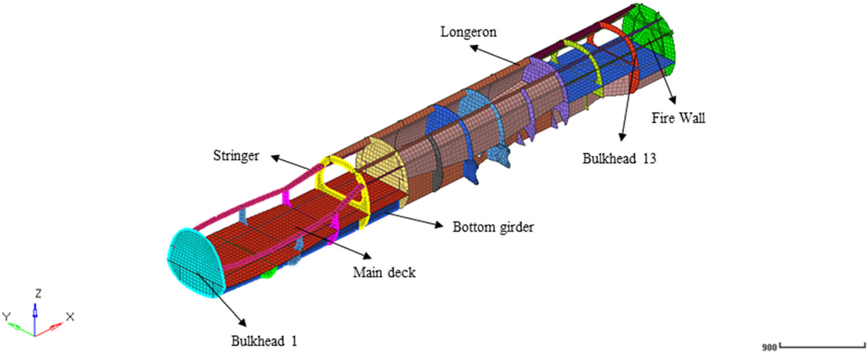
Schematic illustration of MALE UAV structure configuration.
The material properties of the fuselage structure are summarized in Table 2. The composite laminate is designed using material from HexPly W3G282-F593 carbon fiber prepreg with the composition of several plies with stacking sequence described in Table 3.
Material input for finite element analysis
| Material | Density (ton/mm3) | E 11 (MPa) | E 22 (MPa) | v 12 | G 12 (MPa) | G 13 (MPa) | G 23 (MPa) |
|---|---|---|---|---|---|---|---|
| 1. Kevlar Fabric*[23] | 1.4 × 10⁻⁹ | 30,000 | 30,000 | 0.2 | 5,000 | — | — |
| 2. Hexcel W3G282-F593**[24] | 1.6 × 10⁻⁹ | 55,840 | 55,840 | 0.06 | 3,650 | 3,650 | 3,650 |
Note: * Carbon Fiber Composite Materials – Kevlar Fabric (120°C Cure), thickness per ply 0.27 mm, ** Thickness per ply 0.237 mm.
Plies orientation for each component
| Ply orientation | Component | Material |
|---|---|---|
| [+45/90/−45/0/+45/0] s | Skin fuselage | 1 |
| [+45/90/−45/0/0/0/−45/90/+45] | Frames 1–5, 7, 10, 12, 13, Stringer, longeron | 2 |
| [+45/90/−45/0/+45/0/+45/0/−45/90/+45] | Frames 6, 8, 9, 11, Bottom girder | 2 |
The procedure in material modeling is carried out with the following stages. Initially, several layers in the composite section are modeled according to the direction of the layers and the number of layers in the section as shown in Table 3. All composite layers are arranged to form a balanced layer and a quasi-isotropic material. Subsequently, an equivalent-single material of the final composite component is taken to be applied as the homogeneous material in the final analysis. This method is proven to produce robust analysis and reduce computational costs.
5.2 Loads on fuselage
This article presents the loads on the MALE UAV fuselage as follows. The loads on the fuselage are assumed to be applied to each frame along the fuselage. The MALE UAV fuselage consists of 14 frames. Figure 13 shows a typical load for each frame, which is classified into several categories, such as aerodynamics, inertia, attachment force, and fitting force.

Typical load for frame structure evaluation.
These loads are generated by several factors such as mass and distribution, aerodynamics, aircraft geometry, landing gear, engine and thrust, stability and control, mission profile, and fitting. To obtain representative results in topology optimization, the critical flight load and critical ground load have been taken into consideration (Table 4).
Summary of flight and ground loads on the frame
| St. | Critical flight load | Critical ground load | ||||||||||
|---|---|---|---|---|---|---|---|---|---|---|---|---|
| F x (N) | F y (N) | F z (N) | M x (Nm) | M y (Nm) | M z (Nm) | F x (N) | F y (N) | F z (N) | M x (Nm) | M y (Nm) | M z (Nm) | |
| Fr1 | 36 | 0 | −1,458 | 0 | 38 | 0 | −311 | 0 | −1,243 | 0 | −49 | 0 |
| Fr2 | 159 | 0 | −1,984 | 0 | −5 | 0 | −315 | 0 | −1,310 | 0 | 69 | 0 |
| Fr3 | 30 | 0 | −1,568 | 0 | −19 | 0 | −250 | 0 | −1,119 | 0 | 71 | 0 |
| Fr4 | 16 | 0 | −797 | 0 | −1 | 0 | −117 | 0 | −652 | 0 | 4 | 0 |
| Fr5 | 65 | 0 | −1,073 | 0 | −5 | 0 | −176 | 0 | −955 | 0 | 15 | 0 |
| Fr6 | 155 | 0 | −2,681 | 0 | 18 | 7 | −358 | 0 | −2,301 | 0 | −35 | −18 |
| Fr7 | 205 | 0 | −3,767 | 0 | 19 | −9 | −428 | 0 | −3,239 | 0 | −41 | 16 |
| Fr8 | 191 | 0 | −3,619 | 0 | 29 | 0 | −474 | 0 | −3,623 | 0 | −62 | 0 |
| Fr9 | 244 | 0 | −4,813 | 0 | 6 | 0 | 6,652 | 0 | 29,418 | 0 | −2,177 | 0 |
| Fr10 | 224 | 0 | −4,464 | 0 | 18 | 8 | −524 | 0 | −4,184 | 0 | −29 | 21 |
| Fr11 | 90 | 0 | −1,783 | 0 | 14 | −2 | −193 | 0 | −1,744 | 0 | −29 | 4 |
| Fr12 | 17 | 0 | −351 | 0 | 2 | 0 | −49 | 0 | −437 | 0 | −5 | 0 |
| Fr13 | 25 | 0 | −503 | 0 | 3 | 0 | −76 | 0 | −720 | 0 | −8 | −1 |
| Fr14 | −297 | 0 | −1,290 | 0 | −49 | 0 | −208 | 0 | −3,225 | 0 | −50 | 18 |
Aerodynamic load, inertial load, and attachment force are then represented by a single-point load, which is located in the floor beam of each frame. This single-point load is subjected to several loads and moments and distributes the load to certain points in the frame. Meanwhile, the fitting force is calculated based on the landing gear load data.
6 Results
The optimization process was carried out by means of the FEM. With a set of loads applied on the frames of the fuselage, minimum strain energy was set as the objective function while preserving the volume of frames up to 50% is the constraint set for this problem. Some areas of each frame which has a contact or joint with other components were frozen to avoid the optimization process occurring in those particular areas. The setup previously mentioned allows the simulation generates optimum topology to meet the objective function within the limitations that have been set. At the end of the analysis, the stress distribution of the global and local area of the modified structure was compared with the initial structure.
6.1 Topology optimization results
In this study, topology optimization required up to 30 iteration steps to meet the convergence criterion. Figure 14 shows an example of how the iteration progress optimized the strain energy and volume fraction of frame No. 1, along with an illustration of the evolving structure. In this example, after 28 iteration steps, the strain energy had been reduced to 17 J from an initial value of 128 J, while the volume fraction had decreased to 67% from its initial value. The decrease in volume fraction was associated with weight reduction.

Strain energy and volume fraction vs number of iterations.
Figure 14 gives an interesting outlook that the convergence of strain energy and volume fraction occurred in different steps. In this particular instance, the volume fraction and strain energy decreased right away as the optimization was initiated. However, the volume fraction has not changed ten iteration steps earlier than strain energy reaching convergence. Here, it can be concluded that the optimization process focused on accomplishing constraint criterion first before settling for the solution of the objective function. Small changes in the topology have shown a significant impact on the strain energy. In structural analysis, strain energy has a physical meaning as the energy stored in a body due to deformation. In this case, the end form is a frame with some holes. It can be seen that these holes transformed from hooked to more curved. The optimization direction of curve-shaped holes is expected as they indicate less stress concentration; hence, less deformation propagation is likely to develop.
As previously mentioned, the decrease in volume fraction associates with the weight reduction; yet, the relationship is not quite linear. In frame no. 1, a 33% reduction in volume fraction gives a 42% weight reduction. Similar occurrences are present in other frames as shown in Table 6. This finding is expected as the density of the frames is not completely uniform; thus, the decrease in volume may not give the same figure with weight reduction. The uniformity feature of the frames is due to the fact that they are constituted from two combined materials: metal and composite.
Based on Tables 5 and 6, it can be observed that practically all frames had their weight significantly reduced (by more than 20%), but only frame numbers 4, 8, and 9 had minor adjustments, with weight reductions of 14, 10, and 17%, respectively. This circumstance is brought on by the frame’s restriction – these frames cannot be optimized further because they have reached ideal size. Frame numbers 8 and 9 cannot be altered significantly (both frames are dominated by a metal structure, while optimization only works for composite material), while frame number 4 is already relatively small; therefore, no significant weight change occurred. Overall, the optimization process has summed up a 26% weight reduction compared to the initial weight.
Summary of optimization results on typical frame structure
| Before | After | |
|---|---|---|
| Frame 1 |

|

|
| Frame 2 |

|

|
| Frame 3 |

|

|
| Frame 4 |

|

|
| Frame 5 |

|

|
| Frame 7 |

|

|
| Frame 8 |

|

|
| Frame 10 |

|

|
Weight loss percentage on frame structure
| Components | Strain energy | Optimized volume fraction (%) | Weight loss percentage (%) | |
|---|---|---|---|---|
| Initial | Optimized | |||
| Frame 1 | 127.93 | 16.95 | 67 | 42 |
| Frame 2 | 194108.80 | 10709.81 | 71 | 47 |
| Frame 3 | 61806.58 | 4614.39 | 65 | 52 |
| Frame 4 | 58451.79 | 2951.19 | 69 | 14 |
| Frame 5 | 34442.50 | 3894.07 | 87 | 23 |
| Frame 6 | 1766.87 | 946.77 | 68 | 33 |
| Frame 7 | 27858.16 | 2084.85 | 67 | 42 |
| Frame 8 | 852.17 | 256.83 | 77 | 10 |
| Frame 9 | 879.20 | 263.57 | 78 | 17 |
| Frame 10 | 27545.00 | 2773.43 | 97 | 27 |
| Frame 11 | 1911.71 | 1083.58 | 73 | 34 |
| Frame 12 | 72355.59 | 2714.13 | 73 | 44 |
| Frame 13 | 10823.50 | 3068.64 | 77 | 44 |
6.2 Structural strength evaluation
Figure 15 shows the results of the structural evaluation of the overall fuselage construction before the optimization process was carried out. The displacement, plane stress, and shear stress indicate that the fuselage structure shows that the fuselage structure is within the material criteria threshold. The results of the analysis show that the maximum stress values in x-, y-, and xy-planes are 48, 34, and 56 MPa, respectively, which all occur in the area where the metal lugs are installed. In comparison to the metal material strength, the stress is rather low. This evaluation provides the conclusion that the initial structure of the fuselage was designed too optimistically to bear applying loads.

Global FEM results before the optimization.
The topology optimization naturally increases the stress due to the removal of some areas of the frame. This is the expected trade-off which may raise another concern about whether the structure is still safe due to the stress. To evaluate this aspect, global FEM over-optimized fuselage structure was carried out; its results are depicted in Figure 16 showing the structural evaluation after the optimization process. Overall, the value is still under a safe limit. The only concern is the structural response of the metal part in the lug area. Interestingly, the analyses, both before and after optimization, demonstrate that the fuselage frame is not effective in sustaining fuselage load. In reality, the load is dispersed by integral longitudinal structures like girders or stringers. Thus, the maximum stress occurred at the girder in the lug area. In addition, the displacement data shows only 31 mm at the end of the fuselage which is not particularly noteworthy.

Global FEM results after the optimization.
The following findings on the first frame, for instance, are identified by comparing the structural response before and after the optimization. The results show a significant change in shape achieving a weight reduction of up to 42% from the initial weight (Figure 17). Another expected phenomenon is the difference in strength value responses. After the optimization, the stress concentration moves to the removed area. However, the stress value is still below the value of the strength properties of laminated composites.
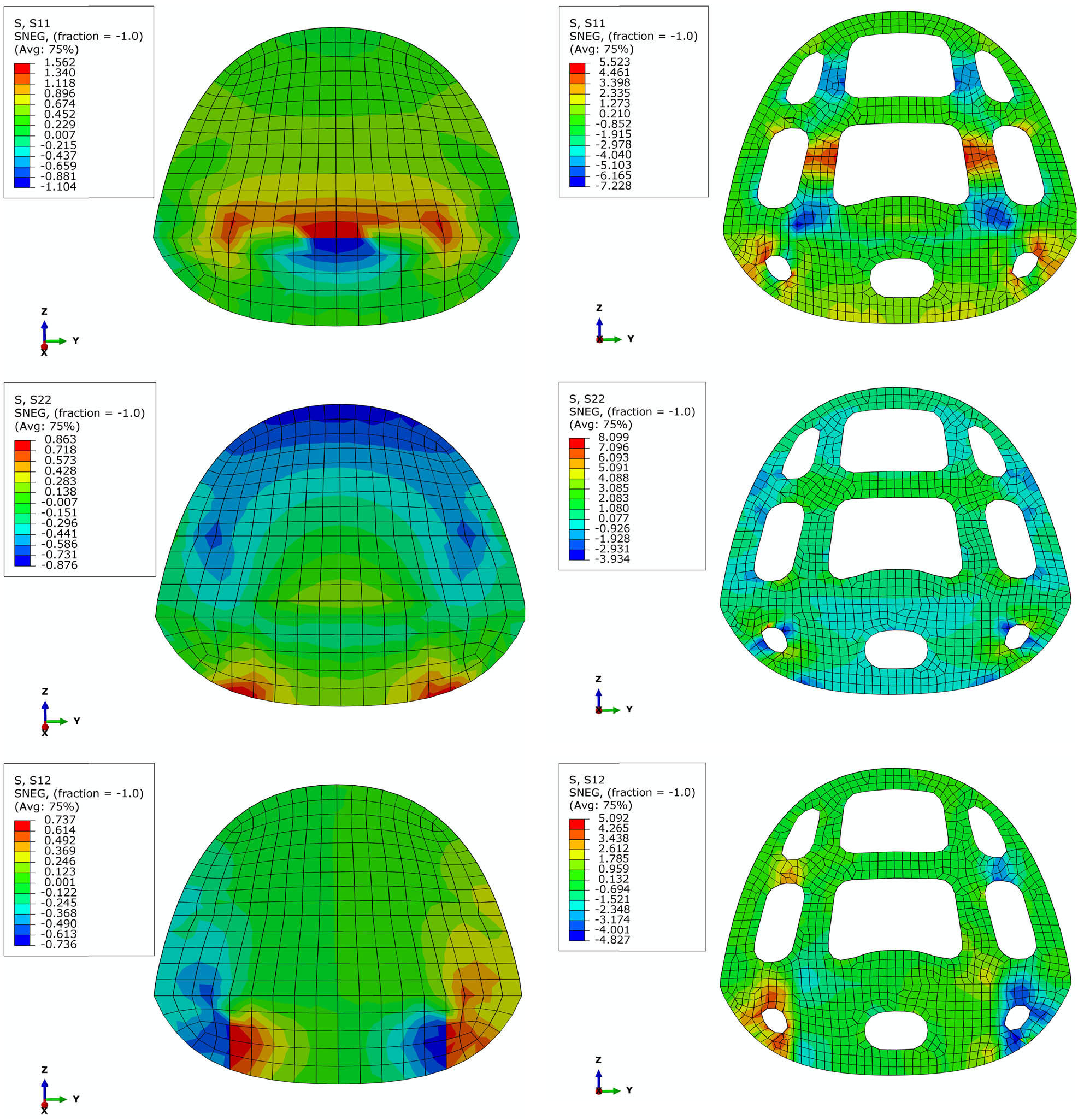
Stress distribution of fuselage frame before and after the optimization.
7 Conclusions
A numerical study on the topology optimization of laminate composite structures using an FEM has been developed. In terms of the benchmark model, the current topology optimization study shows good agreement. The mesh convergence test analysis was conducted to determine the optimal mesh size before performing GFEM. It was found that a mesh size of 50 was considered the best for this model. The fuselage structure’s material properties are made of composite laminate using material from HexPly W3G282-F593 carbon fiber prepreg. The loads used in this study comply with the regulations from STANAG 4671 subpart C. The loads on the fuselage are assumed to be subjected to each frame along the fuselage. The loads on the frame can be classified into several categories such as aerodynamics, inertia, attachment force, and fitting force. The topology optimization study successfully reduced an average of 26% of the overall frame weight.
To achieve better results in the topology optimization process, several factors need to be considered. First, the use of composite materials must be supported by reliable and comprehensive material data allowable. It is also necessary to verify how the data provided by the manufacturer compares with the actual strength data tested. The higher the confidence in the material data, the better the design optimization will be. Second, the optimization process should not only result in a lighter structure but also ensure the safety of the structure from catastrophic failure, which should be the primary constraint in determining the design choice. Lastly, refinement after the topology optimization process is absolutely necessary to avoid structural failure due to small, unexpected factors. Aspects of manufacturability, payload placement, and stress concentration must be given special consideration in determining the final result of the optimization process.
In general, the optimization results can be applied to the frame fuselage component of the MALE UAV. The resulting design from this optimization will significantly lighten the aircraft structure, enabling it to operate more efficiently. During the detailed design phase of aircraft development, the optimization results can be studied more thoroughly, particularly concerning the joiner between components.
Acknowledgments
This work is part of the research activity under the grant of Research Organization for Aeronautics and Space of National Research and Innovation Agency (BRIN).
-
Funding information: This work was supported by the project “Topology optimization of MALE UAV fuselage structure with numerical approach based on finite element method” No. 6/III/HK/2022 under the grant of Research Organization for Aeronautics and Space of National Research and Innovation Agency (BRIN), Bogor, Indonesia.
-
Author contributions: All authors have accepted responsibility for the entire content of this manuscript and approved its submission.
-
Conflict of interest: Authors state no conflict of interest.
-
Data availability statement: The authors declare that the data supporting the findings of this study are available within the article.
References
[1] Taylor JW, Munson K. Jane’s pocket book of remotely piloted vehicles: robot aircraft today. New York (NY), USA: Collier Books; 1977.Search in Google Scholar
[2] Wargo CA, Church GC, Glaneueski J, Strout M. Unmanned Aircraft Systems (UAS) research and future analysis. 2014 IEEE Aerospace Conference; 2014 Mar 1–8; Big Sky (MT), USA. IEEE; 2014. p. 1–16.10.1109/AERO.2014.6836448Search in Google Scholar
[3] Austin R. Unmanned aircraft systems: UAVS design, development and deployment. Hoboken (NJ), USA: John Wiley & Sons; 2011 Sep 20.10.1002/9780470664797Search in Google Scholar
[4] Deaton JD, Grandhi RV. A survey of structural and multidisciplinary continuum topology optimization: post 2000. Struct Multidisc Optim. 2014;49:1–38.10.1007/s00158-013-0956-zSearch in Google Scholar
[5] Kontogiannis SG, Ekaterinaris JA. Design, performance evaluation and optimization of a UAV. Aerosp Sci Technol. 2013 Aug 1;29(1):339–50.10.1016/j.ast.2013.04.005Search in Google Scholar
[6] Jashnani S, Nada TR, Ishfaq M, Khamker A, Shaholia P. Sizing and preliminary hardware testing of solar powered UAV. Egypt J Remote Sens Space Sci. 2013 Dec 1;16(2):189–98.10.1016/j.ejrs.2013.05.002Search in Google Scholar
[7] Iqbal L, Sullivan J. Comprehensive aircraft preliminary design methodology applied to the design of MALE UAV. 47th AIAA Aerospace Sciences Meeting including The New Horizons Forum and Aerospace Exposition; 2009 Jan 5–8; Orlando (FL), USA. AIAA, 2009. p. 431.10.2514/6.2009-431Search in Google Scholar
[8] Goetzendorf‐Grabowski T, Frydrychewicz A, Goraj Z, Suchodolski S. MALE UAV design of an increased reliability level. Aircr Eng Aerosp Technol. 2006 May 1;78(3):226–35.10.1108/17488840610663693Search in Google Scholar
[9] Raymer DP. Aircraft design: a conceptual approach. Reston (VA), USA: American Institute of Aeronautics and Astronautics; 1999. p. 21.Search in Google Scholar
[10] Long CH, Zhang Y, Zuyong CH, Jun XU, Wu J. Topology optimization in lightweight design of a 3D-printed flapping-wing micro aerial vehicle. Chin J Aeronautics. 2020 Dec 1;33(12):3206–19.10.1016/j.cja.2020.04.013Search in Google Scholar
[11] Tempo. Drone Asli Indonesia Elang Hitam, Mirip MQ-9 AS dan CH-4 Cina? Jakarta, Indonesia; 2019. https://tekno.tempo.co/read/1289457/drone-asli-indonesia-elang-hitam-mirip-mq-9-as-dan-ch-4-cina. (in Indonesian)Search in Google Scholar
[12] Anderson JD. Aircraft performance & design. New York (NY), USA: McGraw-Hill Education; 1999.Search in Google Scholar
[13] Roskam J. Airplane. Lawrence (KS), USA: DARcorporation; 2004.Search in Google Scholar
[14] Abaqus analysis user’s manual, Version 6.23. Dassault Systemes. Pawtuckat, USA; 2021.Search in Google Scholar
[15] Sóbester A, Keane A, Scanlan J, Bressloff N. Conceptual design of UAV airframes using a generic geometry service. InInfotech@. Aerospace; 2005 Sep 26–29; Arlington (VA), USA. AIAA, 2005.10.2514/6.2005-7079Search in Google Scholar
[16] Lee JW, Kim JJ, Kim HS, Yoon GH. Application of a layerwise theory for efficient topology optimization of laminate structure. J Mech Sci Technol. 2019 Feb;33:711–9.10.1007/s12206-019-0125-4Search in Google Scholar
[17] Hu Z, Vambol O, Sun S, Zeng Q. Development of a topology optimization method for the design of composite lattice ring structures. Eastern-European J Enterp Technol. 2021 Aug 31;4(1):112.10.15587/1729-4061.2021.238266Search in Google Scholar
[18] Elvas A, Sohouli A, Suleman A. Simultaneous topology and fiber path optimization of composite structures with MAC constraints. Compos Struct. 2022 Aug 15;294:115645.10.1016/j.compstruct.2022.115645Search in Google Scholar
[19] Tong X, Ge W, Sun C, Liu X. Topology optimization of compliant adaptive wing leading edge with composite materials. Chin J Aeronautics. 2014 Dec 1;27(6):1488–94.10.1016/j.cja.2014.10.015Search in Google Scholar
[20] Hu Z, Vambol O. Topological designing and analysis of the composite wing rib. Aerosp Technic Technol. 2020 Nov;27(6):4–14.10.32620/aktt.2020.6.01Search in Google Scholar
[21] Eckrich M, Arrabiyeh PA, Dlugaj AM, May D. Structural topology optimization and path planning for composites manufactured by fiber placement technologies. Compos Struct. 2022 Jun 1;289:115488.10.1016/j.compstruct.2022.115488Search in Google Scholar
[22] Malik PK, Guha A, Seshu P. Topology identification for super-stable tensegrity structure from a given number of nodes in two dimensional space. Mech Res Commun. 2022 Jan 1;119:103810.10.1016/j.mechrescom.2021.103810Search in Google Scholar
[23] Performance Composite. Mechanical Properties of Carbon Fibre Composite Materials, Fibre/Epoxy resin (120°C Cure) [internet]; 2021. http://www.performancecomposites.com/carbonfibre/mechanicalproperties_2.asp.Search in Google Scholar
[24] Hexcel Corporation. HexPly Prepregs [internet]; 2021. www.hexcel.com.Search in Google Scholar
© 2023 the author(s), published by De Gruyter
This work is licensed under the Creative Commons Attribution 4.0 International License.
Articles in the same Issue
- Research Articles
- Investigation of differential shrinkage stresses in a revolution shell structure due to the evolving parameters of concrete
- Multiphysics analysis for fluid–structure interaction of blood biological flow inside three-dimensional artery
- MD-based study on the deformation process of engineered Ni–Al core–shell nanowires: Toward an understanding underlying deformation mechanisms
- Experimental measurement and numerical predictions of thickness variation and transverse stresses in a concrete ring
- Studying the effect of embedded length strength of concrete and diameter of anchor on shear performance between old and new concrete
- Evaluation of static responses for layered composite arches
- Nonlocal state-space strain gradient wave propagation of magneto thermo piezoelectric functionally graded nanobeam
- Numerical study of the FRP-concrete bond behavior under thermal variations
- Parametric study of retrofitted reinforced concrete columns with steel cages and predicting load distribution and compressive stress in columns using machine learning algorithms
- Application of soft computing in estimating primary crack spacing of reinforced concrete structures
- Identification of crack location in metallic biomaterial cantilever beam subjected to moving load base on central difference approximation
- Numerical investigations of two vibrating cylinders in uniform flow using overset mesh
- Performance analysis on the structure of the bracket mounting for hybrid converter kit: Finite-element approach
- A new finite-element procedure for vibration analysis of FGP sandwich plates resting on Kerr foundation
- Strength analysis of marine biaxial warp-knitted glass fabrics as composite laminations for ship material
- Analysis of a thick cylindrical FGM pressure vessel with variable parameters using thermoelasticity
- Structural function analysis of shear walls in sustainable assembled buildings under finite element model
- In-plane nonlinear postbuckling and buckling analysis of Lee’s frame using absolute nodal coordinate formulation
- Optimization of structural parameters and numerical simulation of stress field of composite crucible based on the indirect coupling method
- Numerical study on crushing damage and energy absorption of multi-cell glass fibre-reinforced composite panel: Application to the crash absorber design of tsunami lifeboat
- Stripped and layered fabrication of minimal surface tectonics using parametric algorithms
- A methodological approach for detecting multiple faults in wind turbine blades based on vibration signals and machine learning
- Influence of the selection of different construction materials on the stress–strain state of the track
- A coupled hygro-elastic 3D model for steady-state analysis of functionally graded plates and shells
- Comparative study of shell element formulations as NLFE parameters to forecast structural crashworthiness
- A size-dependent 3D solution of functionally graded shallow nanoshells
- Special Issue: The 2nd Thematic Symposium - Integrity of Mechanical Structure and Material - Part I
- Correlation between lamina directions and the mechanical characteristics of laminated bamboo composite for ship structure
- Reliability-based assessment of ship hull girder ultimate strength
- Finite element method on topology optimization applied to laminate composite of fuselage structure
- Dynamic response of high-speed craft bottom panels subjected to slamming loadings
- Effect of pitting corrosion position to the strength of ship bottom plate in grounding incident
- Antiballistic material, testing, and procedures of curved-layered objects: A systematic review and current milestone
- Thin-walled cylindrical shells in engineering designs and critical infrastructures: A systematic review based on the loading response
- Laminar Rayleigh–Benard convection in a closed square field with meshless radial basis function method
- Determination of cryogenic temperature loads for finite-element model of LNG bunkering ship under LNG release accident
- Roundness and slenderness effects on the dynamic characteristics of spar-type floating offshore wind turbine