
F1 style MGU-H applied to the turbocharger of a gasoline hybrid electric passenger car
-
Albert Boretti


Abstract
We consider a turbocharged gasoline direct injection (DI) engine featuring a motor-generator-unit (MGU-H) fitted on the turbocharger shaft. The MGU-H receives or delivers energy to the same energy storage (ES) of the hybrid power unit that comprises a motor-generator unit on the driveline (MGU-K) in addition to the internal combustion engine (ICE). The energy supply from the ES is mostly needed during sharp accelerations to avoid turbo-lag, and to boost torque at low speeds. At low speeds, it also improves the ratio of engine crankshaft power to fuel flow power, as well as the ratio of engine crankshaft plus turbocharger shaft power to fuel flow power. The energy supply to the ES is possible at high speeds and loads, where otherwise the turbine could have been waste gated, and during decelerations. This improves the ratio of engine crankshaft plus turbocharger shaft power to fuel flow power.
1 Introduction
During a driving schedule, as for example the cold start new European driving cycle (NEDC), a passenger car must accelerate and decelerate. In a traditional powertrain, the power for the acceleration is delivered by the internal combustion engine (ICE), while the power for deceleration is provided by the friction brakes. With kinetic energy recovery systems (KERS), during braking the kinetic energy is stored to be re-used during the following acceleration. The most widely used KERS are electric. In an electric KERS (E-KERS), a motor/generator unit is connected to the driveline and the energy storage (ES) for kinetic energy recovery, charging the energy storage during decelerations and buffering the engine during the following acceleration, coasting or stop. Today’s road HEV have full integration of ICE and a more complex but less efficient version of the KERS permitting more complicate strategies to match fuel economy and emission of certification tests. Racing HEV have more powerful and focused KERS integrated with the ICE. This sort of architecture may also be considered for road HEV.
Vehicles with E-KERS may easily integrate other electric components, as for example an electric water pump (EWP) and an electrically assisted turbocharged (E-TC). The MGU-H is a variant of the E-TC that permits to recharge the ES when there is excess power delivered by the turbine vs. what is requested in the compressor, or deliver to the compressor a power exceeding the turbine power. The present contribution discusses the steady operation of a gasoline direct injection (GDI) engine having an MGU-H. Not relevant to the present simulations, the engine also features a EWP that operates independently from the crank shaft and permits a quicker warm-up thanks to the better temperature control matching the cooling needs at any speed and load with media and metal temperatures.
Different technologies have been proposed in the literature for electrically assisted turbochargers.
A first E-TC technology is proposed in [1] for a Class 8 truck engine. The system consists of a turbocharger with an electric motor-generator integrated into the turbo shaft. The generator extracts the surplus power at the turbine, but the electricity it produces is then used to run a motor mounted on the engine crankshaft. The system permits to recover part of the otherwise wasted energy in the exhaust gases.
An electric assisted turbocharger for a heavy-duty diesel engine is also proposed in [2] but for an urban bus. The variable geometry turbine is replaced with a fixed geometry turbine, connected to an electric motor-generator. The electric motor is used to speed up the turbocharger during accelerations, while the electric generator is used to recover the excess exhaust energy when the engine is operated near the rated speed. This recovered energy helps producing the electrical power needed by the engine auxiliaries.
An electrically assisted turbocharger with a high-speed motor generator built in is also used in [3]. When operating at low speeds, motor assistance permits better combustion, reduced exhaust emissions, improved torque response, and torque boost. At high speeds, it improves efficiency by producing electric power more than the exhaust gas energy. Electro turbo-compounding to regenerate the excess of exhaust energy to turbine is also proposed in [4]. This work is mostly concerned about exhaust heat recovery at high speeds.
Different electric turbo-compounding systems are proposed in [5], an electric-assisted turbocharger, a turbo-generator that is in series with the turbocharger, and a turbo-generator that is in parallel with the turbocharger. Computational results for a 1.8L turbocharged gasoline engine powering a passenger car covering the US06 and FTP75 driving cycles show that the performance of the turbo-generator that is in parallel with the turbocharger is better than those of the other two systems, but this system is much more complicated.
Electric assisting systems are also used to improve the dynamic response of turbocharged diesel engines in [6]. The indirect energy supply with the electrically assisted turbocharger outperforms the direct energy supply with an integrated starter-generator-booster (ISG) mounted on the engine flywheel. an integrated starter-generator-booster for vehicle application. ISG is however the preferred solution when instant power increase is demanded.
Electrically assisted turbochargers are also considered in [7]. The standard turbocharger is modified to accommodate the electric motor-generator within the bearing housing. The device is mostly used as motor to improve engine transient response and low end torque by delivering the extra power needed by the compressor. The device is also as generator during steady state conditions to recover a larger amount of exhaust energy. Reference [7] concludes that the technique allows more engine down-sizing and down-speeding as well as a more efficient turbocharger to engine match.
Figure 1 (from [8]) presents the schematic of the latest F1 engine hybrid powertrain. The hybrid power unit comprises the turbocharged internal combustion engine (ICE) plus an energy store (ES), a motor-generator unit on the driveline (MGU-K) charging the ES when braking, and boosting the ICE when accelerating discharging the ES. The hybrid power unit also comprises a motor-generator unit on the turbocharger shaft (MGU-H). Figure 2 presents a schematic of a turbocharger with a motor/generator unit side of compressor (top) or between compressor and turbine (bottom) as used in F1, for example by Renault or Ferrari during the 2014 season. When the turbine power exceeds the power needed in the compressor, the MGU-H charges the ES. The powertrain comprises the ICE, the ES, the MGU-H (recovery of extra energy at the turbocharger or assistance of the turbocharger acceleration) and the MGU-K (recovery of the braking energy and ICE boost during accelerations). This is the system that will be studied in the present paper for passenger car applications.
![Fig. 1 F1 KERS (ES+MGU-K) and E-BOOST/WHRS (ES+MGU-H) from [8]. The waste energy recovered by the MGU-H and transferred to the ES is minimal and the MGU-H mostly serves as anti-turbo-lag device.](/document/doi/10.1515/nleng-2016-0069/asset/graphic/j_nleng-2016-0069_fig_001.png)
F1 KERS (ES+MGU-K) and E-BOOST/WHRS (ES+MGU-H) from [8]. The waste energy recovered by the MGU-H and transferred to the ES is minimal and the MGU-H mostly serves as anti-turbo-lag device.
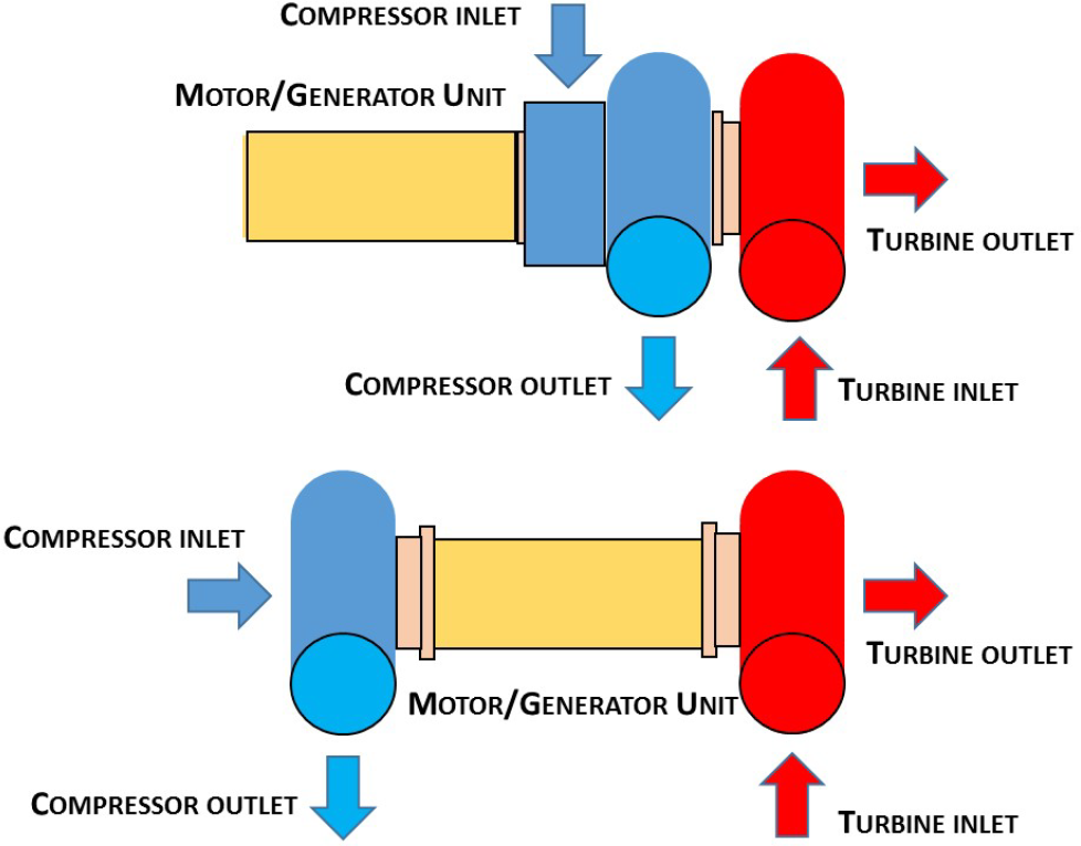
Schematic of a turbocharger with a motor/generator unit side of compressor (top) or between compressor and turbine (bottom) as used in F1.
2 Method
We consider the steady operation of a turbocharged gasoline direct injection engine featuring a motor-generator unit (MGU-H) fitted on the turbocharger shaft. The engine considered is an 86 x 86 mm bore x stroke, 10:1 compression ratio, high pressure directly injected, jet ignited, central direct injector and jet ignition, four valves per cylinder, inline four cylinders’ engine working throttle controlled stoichiometric. The MGU-H is supposed to receive or deliver energy to the same energy storage (ES) of the hybrid power unit that comprises a motor-generator unit on the driveline (MGU-K) in addition to the internal combustion engine (ICE).
High power density, small displacement engines are one of the most promising opportunities to reduce fuel consumption in passenger cars mostly thanks to the down-sizing [9]. Jet ignition and direct injection may be used not only for lean stratified, but also for stoichiometric mixtures helping to work high compression ratio without the occurrence of knock and permitting much faster rates of combustion [10, 11, 12, 13,14]. Reference [15] has discussed the opportunity to build lightweight vehicles environmentally friendly to build that featuring a turbocharger ICE and a KERS are performant and economic to drive.
A virtual engine model was developed by using the GT-SUITE software [16], one of the industry-leading simulation tools. GT-SUITE is used by the most part of the OEMs and their suppliers, plus universities and research centres. Almost 800 of the thousands of papers published reporting about the GT-SUITE models development, validation and application are listed in [17].
Figure 3 presents the model set up. The software used is GT-SUITE [16]. For sake of simplicity, turbine and compressor shaft are connected to the engine crankshaft through gears. The gear ratio is prescribed different for every engine speed and load, but equal for turbine and compressor. This model was developed to simulate a super turbocharger, i.e. a turbocharger connected to the crankshaft through a gear and a continuously variable transmission. The model may also be used to simulate the operation of a MGU-H connected to the turbocharger shaft.
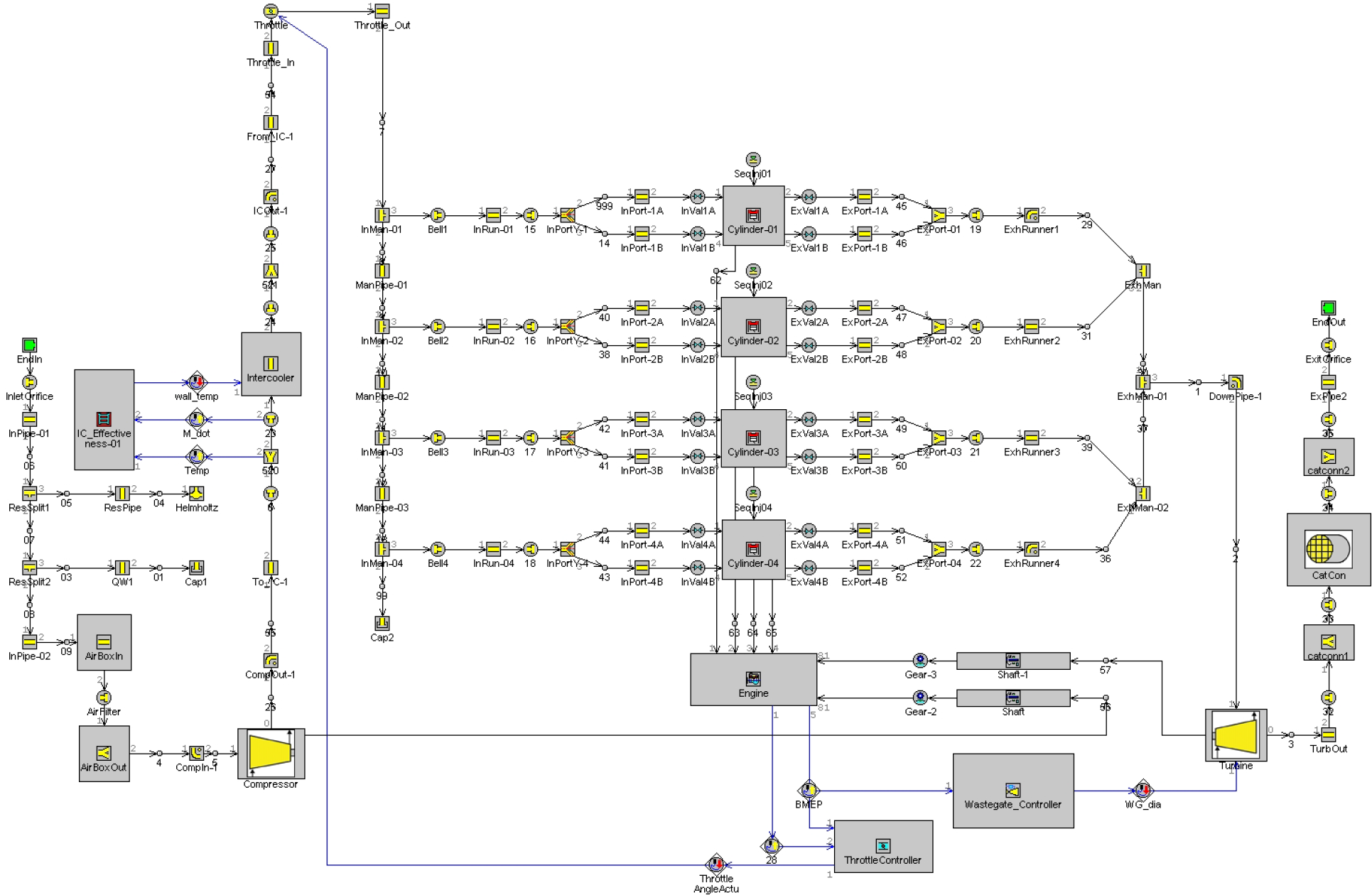
Engine model set-up.
The simulation permits to compute the total efficiency η⋆, defined as the ratio of engine crankshaft power plus the turbocharger shaft power to the fuel flow power, and the total power at the turbocharger shaft and the engine crankshaft. From the power of compressor and turbine, the power at the crankshaft is then obtained. This permits to compute the efficiency η, defined as the ratio of engine crankshaft power to the fuel flow power. Total and engine brake mean effective pressure BMEP⋆ and BMEP are similarly computed.
Figure 4 are the compressor and turbine maps, reduced speed and efficiency vs. pressure ratio and reduced mass flow rate. The simulations are performed for a specific turbocharger that has been selected for traditional operation without MGU-H. With MGU-H (o super turbocharger gear and continuously variable transmission) the optimum turbocharger differs from this selection.
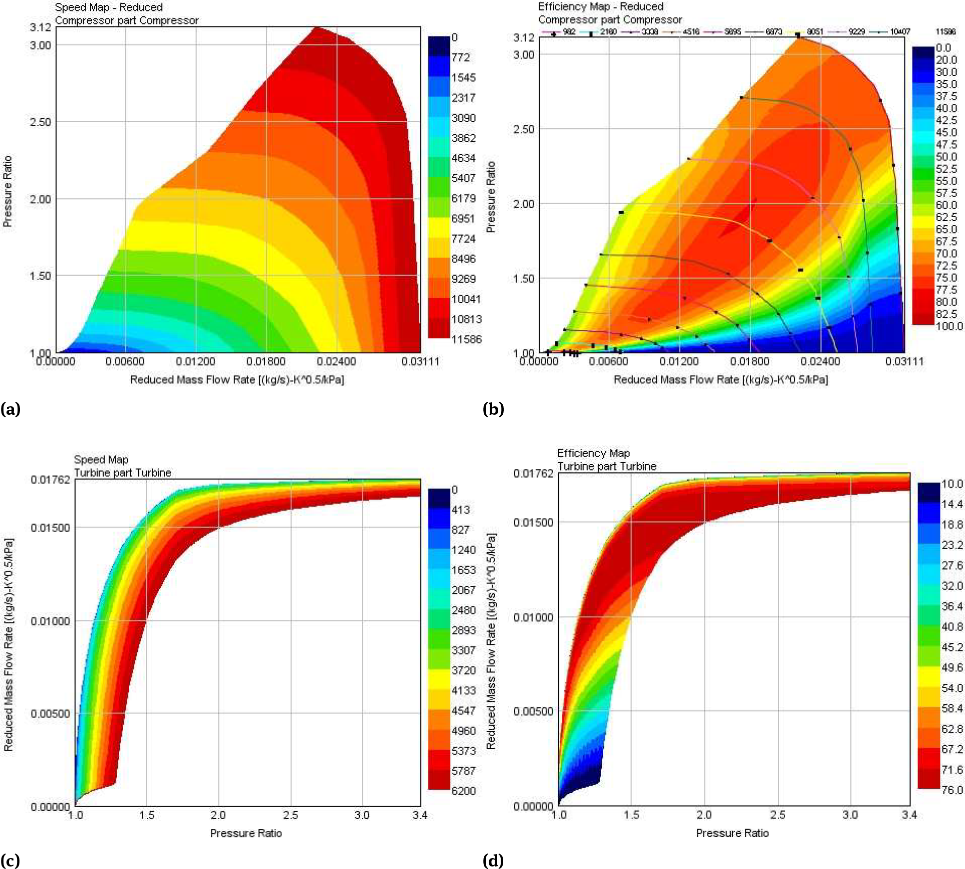
Compressor and turbine maps: a) compressor reduced speed and b) compressor efficiency vs. pressure ratio and reduced mass flow rate. c) turbine reduced speed and d) turbine efficiency vs. pressure ratio and reduced mass flow rate.
3 Results
The GT-SUITE software [16] model proposed here is not a novelty, as the use of similar models is part of the day-to-day process of design and development of novel power trains. Combustion is modelled through a Wiebe function of tabulated parameters vs. speed and load. Knock is simply modelled through the empirical formulation of [18].
Aim of the present simulations is to provide a rather qualitative assessment of the improvements the motor-generator unit (MGU-H) fitted on the turbocharger shaft may have in terms of fuel economy. Throttle opening, wastage opening and speed of turbine and compressors are the parameters considered to control the load in the engine working with a constant stoichiometric air-to-fuel ratio. As the emission rules will be redefined soon to better reflect real driving conditions, the totality of the engine map of a gasoline engine must be stoichiometric to permit the three-way catalytic conversion.
The turbocharger is selected for traditional operation with a waste gate and perfect balance in between turbine output and compressor demand. The results are therefore not expected to deliver optimum performances, as the turbocharger must be redesigned to fully benefit from the MGU on the turbocharger shaft.
The efficiency maps of the engine in Figure 5 presents the performance parameters at wide open throttle - full load - as well as at part loads. Results are preliminary and specific to a turbocharger selection. By charging the turbocharger, results will vary.
is the turbocharger speed.
is the power at the turbocharger shaft.
is the power at the engine crankshaft.
is the power at the turbocharger shaft and the engine crankshaft.
is the power at the turbocharger shaft to the power at the engine crankshaft.
is the efficiency η defined as the ratio of the engine crankshaft power to the fuel flow power.
is the efficiency η⋆, defined as the ratio of engine crankshaft power plus the turbocharger shaft power to the fuel flow power.
is the difference in between the two efficiencies η⋆ - η.
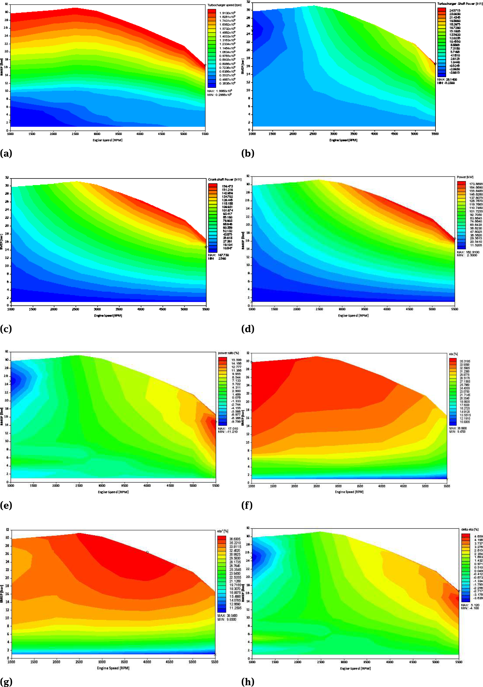
Computed performance parameters vs. engine brake mean effective pressure (BMEP) and speed. a) turbocharger speed. b) power at the turbocharger shaft. c) power at the engine crankshaft. d) power at the turbocharger shaft and the engine crankshaft. e) power at the turbocharger shaft to the power at the engine crankshaft. f) efficiency η defined as the ratio of the engine crankshaft power to the fuel flow power. g) efficiency η⋆, defined as the ratio of engine crankshaft power plus the turbocharger shaft power to the fuel flow power. h) difference in between the two efficiencies η⋆ -η.
These parameters are proposed vs. engine brake mean effective pressure (BMEP) and speed. The BMEP is the engine specific torque output at the crankshaft.
The wide-open-throttle engine BMEP vs. speed with the MGU-H increases at low speeds, where otherwise the exhaust gas energy is not sufficient to provide a significant boost. With the MGU-H, in every operating point, the power produced by the turbine may be larger, equal or smaller than the power requested by the compressor, with negative, zero or positive power produced by the MGU. At medium to high speeds, the engine with the MGU-H is controlled to produce the same BMEP that the engine without. At lower speed, the engine with the MGU-H is controlled to produce a larger BMEP. At low engine speeds, a constant BMEP of about 30 bar same of top medium speed BMEP value can be delivered. Without MGU-H, BMEP may otherwise drop to values as low as 10 bar at minimum speed.
The wide-open throttle engine efficiency η vs. speed with the MGU-H also increases at low speeds. The energy for the extra compression work is drawn from the energy store. This efficiency is the engine power output at the crankshaft vs. the fuel flow power. At medium to high speeds, the engine with the MGU-H is controlled to produce the same BMEP and the efficiency η is about same. At lower speed, the engine with the MGU-H is controlled to produce a larger BMEP and the efficiency η drastically increases. Without MGU-H, the efficiency reduces at low speeds from the top value of about 36% at mid speeds up to about 33% at minimum speed. With the MGU-H, this apparent engine efficiency increases up to about 37% at minimum speed.
The difference in between the wide-open throttle engine efficiencies η and η⋆ vs. speed with the MGU-H provides a better description of the overall energy balance. η is the engine power output at the crankshaft vs. the fuel flow power. η⋆ is the power out at the crankshaft and the turbocharger shaft vs. the fuel flow power. At medium to higher speeds, the power produced by the turbine is larger than the power requested by the compressor, and therefore extra energy can be delivered to the energy store. Therefore, η⋆ is larger than η of up to about 2% at maximum speed. At lower speeds, the power produced by the turbine is smaller than the power requested by the compressor. Therefore, energy is drawn from the energy store. This makes η⋆ smaller than η of up to about 2% at minimum speed.
The MGU-H fitted to the turbocharger shaft permits to recover at high speeds and loads the energy to the turbine otherwise waste gated. This is obtained mostly above 4,000 rpm. At high speeds, the top loads may also be increased, i.e. in addition to the increase the total fuel conversion efficiency, also the torque and power output at the crankshaft can be improved. This is the result of an additional degree of freedom to perform a fine tuning of the operation of turbine and compressor. While in a traditional turbocharger the opening of the waste-gate and the throttle are the only parameters to control the turbocharger operating points, in the proposed design there is an additional parameter that is the power supply at the turbocharger shaft that permits to deviate from the perfect balancing of turbine and compressor powers. The gains are relatively small but widespread.
The MGU-H also permits to increase the boost pressure, in this case dramatically increasing the torque and power output of the engine at the given speeds, when the energy available at the turbine is insufficient to properly run the compressor and achieve the desired flow rate and pressure boost, as it is the case at low speeds, 1,000 to 3,000 rpm. As the flow rate through the turbine increases and the speed of the turbine also increases, the speed of the compressor increases, the boost pressure increases and the flow rate across the engine increases. It is possible to recover the available waste energy to increase the torque and power output of the engine at the given speeds. Not necessarily the supply of power by the energy store translate in a decrement of the total fuel conversion energy, as the crank shaft power output drastically increases. At low speeds, the total fuel conversion energy may be smaller than at mid speeds, but still larger than the efficiency the engine could have without MGU-H.
The extra power produced by the turbocharger at high speeds may reach more than 10% of the crankshaft power. The extra power requested by the turbocharger at low speeds does not reach the 5% of the crankshaft power. Relatively small power supplies at the turbocharger shaft may indeed drastically increase speed of turbine and compressor and boost. The drastic increment of BMEP is not paid at the expenses of a significant reduction of the total fuel conversion efficiency η⋆. While the efficiency gains at high speed may be above 4%, the losses at low speed are in the worst cases well below 2%.
To be mentioned, the round-trip efficiency MGU-H to battery to MGU-H is not unity [19], as it is assumed in Figure 5. The power to the turbocharger shaft vs. the power from the battery may be about 87-89 %. The power to the battery vs. the power to the turbocharger shaft may be about 72-87%. This impacts the value of η⋆, reducing the positive differences η⋆ - η of a factor of 23% to 38%. The total fuel conversion efficiency of Figure 2 is indeed a conventional measure, as the power to the crankshaft or to the turbocharger shaft are used for different goals, namely to propel the vehicle or to charge the energy store.
Every transformation of energy, from mechanical to electric to chemical, and back from chemical to electric to mechanical occurs with an efficiency less than 100%. This is the reason why purely mechanical systems - i.e. super turbochargers where the turbocharger shaft is connected to the crankshaft through a variable speed mechanism - may be considered in non-hybrid electric vehicles (non-HEV) to deliver same or better benefits within a traditional power train arrangement. In case of HEV, obviously the use of a MGU-H is much simpler and straightforward.
4 Conclusions
The motor-generator unit (MGU-H) fitted on the turbocharger shaft permits at steady, high speeds a recovery of the exhaust energy (no waste-gate). It also permits to recover the waste energy during decelerations. During steady operation, the use of a MGU-H translates in an improvement of the total fuel conversion efficiency, power to the turbocharger shaft plus power to the crankshaft vs. fuel flow power, of up to 4-5%. This conventional measure is however optimistic, as the crankshaft will deliver power to the wheels through the transmission, while the turbocharger shaft will deliver power to the energy store (ES) through the MGU-H. The energy stored from the turbocharger, similarly to the energy collected during regenerative braking, will ultimately power the wheels but only through the MGU-K and the transmission, or the turbocharger through the MGU-H when the compressor demands exceeds the turbine output.
The MGU-H is mostly used to increase the boost pressure, thus increasing the brake mean effective pressure (BMEP) output, when the energy available at the turbine is insufficient to properly run the compressor, for steady, low speed. For what concerns pure full load engine torque and power, for the specific turbocharger selection, it increases dramatically at low speeds, while it improves at a much-limited extent at high speeds. Other turbocharger selections may deliver different performances. The low speed BMEP may be raised up to the maximum values of 30 bar, producing a high-desirable about flat torque from minimum speed to the medium speed where maximum torque is achieved with conventional turbochargers. The system also helps considerably during accelerations, as the turbo-lag is practically cancelled.
In terms of cost-benefit analysis of this F1 technology applied to road vehicles, this is left to the vehicle designer and depends heavily on the product to create. As first target segments, the technology may be suitable for use in hybrid electric luxury vehicles and sports cars powered by turbocharged gasoline or diesel engines, with opportunity to move to off-roaders and saloons / sedans, and then to family and economy cars hybrid electric depending on the evolution of the costs of the components, ES (energy store), motor-generator unit on the driveline (MGU-K), motor-generator unit on the turbocharger shaft (MGU-H) and turbocharger.
In conclusions, today road hybrid electric vehicles (HEV) may definitively benefit from turbocharging with MGU-H for both performances and fuel economy. The major advantages are the flat, high, low to medium speed torque and the removal of the turbo-lag during accelerations. The waste energy recovery, either for the exhaust energy otherwise waste-gated at high load and speed, or during decelerations, is widespread over the map, but this translates in relatively small benefits.
Abbreviations
- KERS
kinetic energy recovery systems
- E-KERS
electric KERS
- E-TC
electric turbocharger
- NEDC
New European Driving Cycle
- ICE
internal combustion engine
- ES
energy store
- EWP
electric water pump
- MGU-K
motor-generator unit on the driveline
- MGU-H
motor-generator unit on the turbocharger shaft
- GU
generator unit
- MU
motor unit
- UDC
urban driving cycle
- EUDC
extra urban driving cycle
- TC
turbo-charger
- η
power out at the crankshaft vs. the fuel flow power
- η⋆
power out at the crankshaft and the turbocharger shaft vs. the fuel flow power
References
[1] Hopmann, U. and Algrain, M., “Diesel Engine Electric Turbo Compound Technology,” SAE Technical Paper 2003-01-2294, 2003, 10.4271/2003-01-2294.Suche in Google Scholar
[2] Millo, F., Mallamo, F., Pautasso, E., and Ganio Mego, G., “The Potential of Electric Exhaust Gas Turbocharging for HD Diesel Engines,” SAE Technical Paper 2006-01-0437, 2006, 10.4271/2006-01-0437.Suche in Google Scholar
[3] S. Ibaraki, Y. Yamashita, K. Sumida, H. Ogita and Y. Jinnai, Development of the “hybrid turbo,” an electrically assisted turbocharger, Mitsubishi Heavy Industries, Ltd. Technical Review Vol. 43 No. 3 (Sep. 2006). http://www.mhi-global.com/company/technology/review/pdf/e433/e433036.pdf, 2006, (accessed October 15, 2015).Suche in Google Scholar
[4] Patterson, A., Tett, R., and McGuire, J., “Exhaust Heat Recovery using Electro-Turbogenerators,” SAE Technical Paper 2009-01-1604, 2009, 10.4271/2009-01-1604.Suche in Google Scholar
[5] Wei, W., et al. “Comparative study on electric turbo-compounding systems for gasoline engine exhaust energy recovery.” ASME Turbo Expo 2010: Power for Land, Sea, and Air. American Society of Mechanical Engineers, 2010.10.1115/GT2010-23204Suche in Google Scholar
[6] Katrašnik, Tomaž, et al. “An analysis of turbocharged diesel engine dynamic response improvement by electric assisting systems.” Journal of engineering for gas turbines and power 127.4 (2005): 918-926.10.1115/1.1924533Suche in Google Scholar
[7] Terdich, N. and Martinez-Botas, R., “Experimental Efficiency Characterization of an Electrically Assisted Turbocharger,” SAE Technical Paper 2013-24-0122, 2013, 10.4271/2013-24-0122.Suche in Google Scholar
[8] M. Petrány, How Formula One’s Amazing New Hybrid Turbo Engine Work. http://jalopnik.com/how-formula-ones-amazing-new-hybrid-turbo-engine-works-1506450399, 2014 (accessed October 15, 2015).Suche in Google Scholar
[9] P. Whitaker, Powertrain strategies for the 21st century, www.umtri.umich.edu/sites/default/files/Paul.Whitaker.AVL_.PTS21.2015.pdf, 2015 (accessed October 15, 2015).Suche in Google Scholar
[10] Boretti A. and H. C. Watson, “The lean burn direct-injection jet-ignition gas engine,” International Journal of Hydrogen Energy, Vol. 34, No. 18, pp. 7835-7841, 2009.10.1016/j.ijhydene.2009.07.022Suche in Google Scholar
[11] Boretti A., H. C. Watson and A. Tempia, “Computational analysis of the lean burn direct-injection jet-ignition hydrogen engine,” Proceedings of the Institution of Mechanical Engineers, Part D: Journal of Automobile Engineering, Vol, 224, No. 2, pp. 261-269, 2009.10.1243/09544070JAUTO1278Suche in Google Scholar
[12] Boretti A., R. Paudel and A. Tempia, “Experimental and computational analysis of the combustion evolution in direct injection spark controlled jet ignition engines fuelled with gaseous fuels,” Journal Proceedings of the Institution of Mechanical Engineers, Part D: Journal of Automobile Engineering, Vol. 224, No. 9, pp.1241-1261.10.1243/09544070JAUTO1465Suche in Google Scholar
[13] Green Car Congress, MAHLE Jet Ignition for Ferrari F1 as well as sub-200 g/kWh BSFC in light-duty engine; on-road and stationary applications, www.greencarcongress.com/2016/07/20160711-mahle.html, 2016, (accessed September 9, 2016).Suche in Google Scholar
[14] Bunce, M. and Blaxill, H., “Sub-200 g/kWh BSFC on a Light Duty Gasoline Engine,” SAE Technical Paper 2016-01-0709, 2016.10.4271/2016-01-0709Suche in Google Scholar
[15] A. Boretti, Performing, fun-to-drive, economical and environmentally friendly mobility solution, Journal of Power Technologies, Vol. 93, No. 4, pp. 194-201, 2013.Suche in Google Scholar
[16] Gamma Technologies LLC, GT-SUITE Overview. https://www.gtisoft.com/gt-suite/gt-suite-overview/, 2015 (accessed October 15, 2015).Suche in Google Scholar
[17] Gamma Technologies LLC, GT-SUITE Publications. https://www.gtisoft.com/gt-suite/publications/, 2015 (accessed October 15, 2015).Suche in Google Scholar
[18] Douaud, A. and Eyzat, P., “Four-Octane-Number Method for Predicting the Anti-Knock Behavior of Fuels and Engines,” SAE Technical Paper 780080, 1978, 10.4271/780080.Suche in Google Scholar
[19] A. Boretti, Comparison of regenerative braking efficiencies of MY2012 and MY2013 Nissan Leaf, International Journal of Engineering and Technology Innovation, Vol. 6, No. 3, July 2016, pp. 214-224.Suche in Google Scholar
© 2017 Walter de Gruyter GmbH, Berlin/Boston
This article is distributed under the terms of the Creative Commons Attribution Non-Commercial License, which permits unrestricted non-commercial use, distribution, and reproduction in any medium, provided the original work is properly cited.
Artikel in diesem Heft
- Frontmatter
- A New Computational Technique for the Generation of Optimised Aircraft Trajectories
- Modelling of Imbibition Phenomena in Fluid Flow through Heterogeneous Inclined Porous Media with different porous materials
- Double dispersion effects on non-Darcy free convective boundary layer flow of a nanofluid over vertical frustum of a cone with convective boundary condition
- F1 style MGU-H applied to the turbocharger of a gasoline hybrid electric passenger car
- Nonlinear control systems - A brief overview of historical and recent advances
- An analytical method with Padé technique for solving of variational problems
- Influence of Lorentz force, Cattaneo-Christov heat flux and viscous dissipation on the flow of micropolar fluid past a nonlinear convective stretching vertical surface