Life Estimation and Creep Damage Quantification of Service Exposed Reformer Tube
-
A. Raj


Abstract
This paper deals with evaluation of creep damage of ~11 years service exposed primary hydrogen reformer tube made of HP-40 grade of steel in a petrochemical industry, which has been carried out in terms of Kachanav’s continuum damage mechanics (CDM) model (K-model) and Bogdanoff model (B-model) based on Markov process. Residual life of the tubes was estimated based on hot tensile, conventional creep deformation under identical test conditions, optical microscopy and fractography. Accumulation of damage due to creep has been quantified through microstructural studies. The as received tubes did not reveal any degradation in the material like creep cavitation or voids, but there was indeed loss of tensile strength from room temperature to 870°C for the bottom portion of the tube due to ageing and overheating. Scatter in creep deformation behaviour of the material is probably due to variation in mode of fracture and scatter in voids. From statistical point of view, Weibull distribution pattern for analysing probability of rupture due to void area shifts with increase in true strain towards the higher population of void. The estimation of mean time to reach a specific damage state from K- model and B-model is in close agreement with that of experimental data and can describe the sudden changes of the creep damage in the tertiary region as well. A remnant life of >10 years is estimated at the operating stress–temperature conditions of the top as well as bottom portion of the tube.
Introduction
Life of reformer tubes is limited because of prolonged exposure to aggressive environment like high temperature and stresses. Premature failure of these tubes can take place due to service ageing which is the major cause for rupture.
Steam reforming, auto-thermal or secondary reforming is the key technology in today’s petrochemical and fertilizer industries. Natural gas is used for production of ammonia, methanol, hydrogen, carbon monoxide, etc. Catalytic chemical conversion of natural gas with steam and/or oxygen-containing gas is used in reforming reaction. Hydrocarbon feed reacts with steam to produce synthesis gas in catalyst packed tubes. Main reactions concerning steam reforming of higher hydrocarbons are [1]:
Steam reforming of methane:
This process is highly exothermic
Water gas shift reaction:
This process is endothermic
HP40 austenitic stainless steels are commonly used materials for reformer tubes in petrochemical industries, and they are operating above 900°C. Amongst them HP40Nb and microlloyed steel is more popularly used around the world for such application. Both HK and HP series are centrifugally cast austenitic stainless steels and widely used for reformer tubes in the petrochemical industry for ammonia, methanol and hydrogen plants. The main criteria for their selection are their high creep strength at and above 900°C [5–7]. But in remaining life estimation studies of these materials, scatter characteristic of service exposed material is not taken into account for damage.
Under service exposure condition, reformer tubes have been subjected to carbonization, oxidation, overheating, stress corrosion cracking, sulphidation and thermal cycling. Overheating of the tubes leads to early creep damage and embrittlement [1–5]. Traditional stainless steel application for vertical reformer tubes has been gradually replaced or substituted by centrifugally cast HK40 alloys and subsequently by HP-modified alloys. Even after these advancements, many reformers fail during service within a period of 3–15 years, though their designed performance is specified as 11.4 years. On the other hand, it is noteworthy that despite most of these tubes have a specific design life of 10–15 years, literature survey has revealed that they can have a significant remnant life beyond their specified design life [6]. This is estimated by carrying out residual life assessment (RLA) studies performed at progressive intervals during a well-planned shut down, both by non-destructive evaluation techniques and also by destructive tests like accelerated creep or stress rupture tests above the operating hoop stress level of the tubes. Balance or residual life of the tubes can then be estimated by using Larson–Miller Parameter (LMP) equation [2].
Nucleation and growth of cavities or voids at grain boundaries or even at precipitate/matrix interface are responsible for creep rupture of the tubes. Quantitative metallography evaluation of creep cavitation or void has already been studied on this material and is reported elsewhere [8].
In the present work, accumulation of creep strain data of ~11 years service exposed reformer tube made of HP40 grade of steel in a petrochemical industry has been studied for different stresses at 870°C. The results are supported with a quantitative metallographic study on the extent of creep cavitation and statistical analysis of void area fraction carried out on the service exposed reformer tube material at 870°C/50 MPa and 870°C/68 MPa, respectively. Simulation-based continuum damage mechanics (CDM) model or K-model and Bogdanoff model (B-model) based on Markov process have been applied for analysing and estimating creep damage evolution of the material after 11 years service exposure.
Material and experimental procedure
The tube material used in this study is made of HP40 grade of steel which is about 11 years service exposed and operating at 870°C, though the designed operating temperature of the tube specified by the plant is 920°C. The tubing material is equivalent to 25Cr35Ni1Nb0.2Ti0.01Mo. Room- and high temperature (850°C, 870°C and 890°C) tensile tests of the material were carried out as per ASTM-8M standard, which enables one to establish the operating stress level during creep tests. The stresses at 870°C and above σh (the operating hoop stress) were chosen in a way so that fracture occurs reasonably within a stipulated time frame. Conventional creep tests of the tubes at 870°C were conducted as per ASTM E 139/83 specification in single point ATS Creep Testing Machines (2T capacity), equipped with a three zone split furnace and maintaining zonal temperature within ±2°C with a high precision controller. Strain measurements were made as per ASTM E 139/83 standard procedure, with an Linear Variable Displacement Transformer (LVDT) attachment in the bottom pull rod, outside the furnace but connected to both the extensometers fixed at the top and bottom portion of the specimen gauge length, well within the furnace of the ATS creep testing machine. Round bar cylindrical solid specimens having a gauge diameter of 5.0 mm and a gauge length of 28.47 mm were chosen both for tensile and for creep tests [8]. Creep specimens were loaded at 50–68 MPa/870°C. The operating hoop stress σh (13.46 MPa) was evaluated using the following formula:
where P is the operating pressure in MPa, t is the thickness of the tube in mm and D is the mean diameter in mm. The stress rupture data have been plotted in terms of stress versus LMP:
where T is the absolute temperature in K, tr is the rupture time in hours and C is a constant generally taken as 20. For this grade of steel two values of C (C = 15 and C = 20) were considered (see Table 1) for balance or remaining life prediction, since the major alloying element in this grade of steel is Ni.
Remaining life at different temperature with varying C (LMP constant) value.
| Component (service exposed) | Hoop stress (MPa) | Temperature (°C) | C (LMP constant) | LMP of service-exposed material | Life (tr), (years) | Remaining life (RL)*, (years) |
| Reformer tube (Top) | 13.46 | 870 | 20 | 30800 | >10 | >10 |
| 15 | 24100 | >10 | >10 | |||
| 920 | 20 | 30800 | >10 | >10 | ||
| 15 | 24100 | 18 | 7 | |||
| Reformer tube (Bottom) | 870 | 20 | 30600 | >10 | >10 | |
| 15 | 24100 | >10 | >10 | |||
| 920 | 20 | 30600 | >10 | >10 | ||
| 15 | 24050 | 17 | 6 |
In the present investigation, a set of four specimens were tested under identical condition to examine the statistical creep behaviour. Scatter in voids was quantified from light optical microscopy (LOM), scanning electron microscope (SEM) – JEOL equipped with image analysing technique and EDX analyser. Identification of various elements was carried out with EDX. Details of this technique are reported in Ref. [8]. Fractographic features were recorded and studied for all the crept samples in the SEM. The other half of the creep ruptured pieces were cut longitudinally along the mid plane, mirror polished through conventional metallographic technique to reveal creep cavity [8]. For crept and ruptured specimens, quantification of damage in terms of voids was made both at perpendicular and at parallel directions to the loading axis of the gauge length of the specimens, on a plane which corresponds to the midsection of the specimen diameter at different distances from the ruptured surface. Ten optical images at diametric locations were recorded digitally at 400X. Only after appropriate grey-thresholding, these optical images have been analysed with a view to obtaining the void area as a function of true strain after creep rupture.
It is well established [8] that true stain is a function of the diameter (D) of the specimen at the specific transverse plane and is represented by:
where D is the measured diameter and D0 is the original diameter of the specimen. For the purpose of maintaining uniformity, void area was normalized with respect to true strain which has been measured from crept and ruptured specimens as shown in Figure 5. A detailed analysis of this technique and its interpretation is given elsewhere [8].
Results and discussion
Microstructure evaluation
Scanning Electron Micrographs in secondary electron mode Figure 1(a)–(d) of as received service exposed tubes did not exhibit any sign of degradation including voids or creep cavitation and decarburization. Both the top and bottom portions of the reformer tube revealed a columnar type of microstructure (Figure 1(a) and (d)). Basically two types of carbides are revealed in the EDX analysis – (a) Cr23C6 and (b) niobium-rich carbides as intra-dendritic carbides (light grey ones), with presence of some nickel and silicon in it (Figure 1). They are primary carbides. Nb-rich carbides appear to be coarsened and coagulated. Thus, one could see various morphology of the precipitates in the intra-dendritic region.
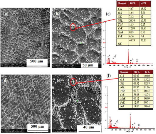
SEM micrograph revealing microstructure of as received top and bottom portions of the reformer tube with EDAX analysis of Cr- and Nb-rich precipitates.
Formation of coarse carbides at dendritic boundaries in the bottom region of the tube was mainly due to overheating with gradual disappearance of fine intra-dendritic precipitates as well [9] (Figure 1). Due to ageing, these carbides would coarsen and gradually shape themselves as worm [9].
Hot tensile and conventional creep tests of service exposed reformer tubes
From the hot tensile strength data, creep loads at 870°C were selected in the range of 50–68 MPa. Hardness [8] and ultimate tensile strength results (Figure 2(a) and (b)), particularly for the bottom portion of the tube when compared with the standard NRIM data of similar grade of steel [10], have clearly indicated that the material has become softened due to prolong ageing. This observation could be correlated with formation of coarse carbides at dendritic boundaries with gradual disappearance of fine intra-dendritic precipitates as well at the bottom portion of the tube (Figure 1). Room temperature as well as high temperature ductility of both the bottom and top portions of the service exposed reformer tubes were in any case lower (Figure 2(a) and (b)) than that of the standard NRIM data of similar grade of steel (i.e. vigin material) [10], which is normally expected for prolong service-exposed materials.
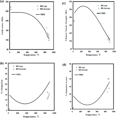
Graphical representation of tensile data of the top and bottom portions of service exposed primary reformer tube as compared with the NRIM virgin data: variation of (a) yield strength, (b) ultimate tensile strength, (c) % elongation and (d) % reduction in area with test temperature.
Conventional creep curves of the service exposed reformer tubes at stress levels 50–68 MPa/870°C (Figure 3(a)–(h)) and as well as their corresponding creep strain rate curves (Figure 3(i)–(p)) clearly exhibit substantial amount of scatter in creep deformation and absence of the primary creep (stage I) region in the scatter creep curves. It should be noted that no valid service history records were available for the individual tubes; thus, it is possible that the current test samples were machined from tubing which was replaced during an earlier shut-down of the refinery, i.e. 5 years ago.
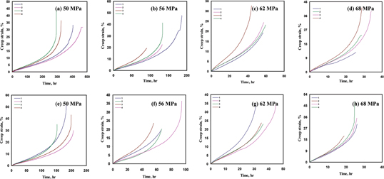
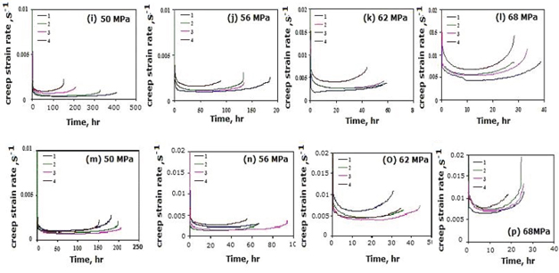
(a–d) Scatter creep curves at 870°C and at various stress levels of 11 years service exposed primary reformer tubes (top region); (e–h) Scatter creep curves at 870°C and at various stress levels of 11 years service exposed primary reformer tubes (bottom region); (i–l) Creep strain rate curves at 870°C and at various stress levels of 11 years service exposed primary reformer tubes (top region); (m–p) Creep strain rate curves at 870°C and at various stress levels of 11 years service exposed primary reformer tubes (bottom region).
An atlas of fractograph of the crept specimens (service exposed top as well as bottom portion) of the reformer tubes is exhibited in Figure 4. It is clearly seen that even though samples were crept under identical stress-temperature condition, mode of rupture appears to be different. Similar kind of observation was found by Garofalo et al. [4] and Roy et al. [11]. The creep ruptured surfaces as shown in (Figure 4(c), (e), (g), (k), (p)) had undergone considerable amount of oxidation. Detailed fractographic analysis indicated that whatever variation in the mode of fracture one observes, it could be only due to the influence or effect of oxide scale formation (Figure 4(e), (i), (g), (k)) because all creep tests were conducted in oxidizing atmosphere, i.e. in air. Due to considerable amount of oxidation, the effective cross-section area required for load bearing capacity of the crept specimen actually decreases, and this leads to catastrophic rupture with shear mode. Crept samples of top portion of the tube ruptured in a relatively brittle manner with 16.4% elongation. Bottom portion of the tube ruptured showed a quasi cleavage fracture with 17% elongation (see Figure 4(c), (d), (g), (k), (o), (p)) and it also shows brittle failure with cleavage facets (see Figure 4(g), (o), (p)) respectively. On the other hand, it is noteworthy that in the top section (Figure 4(a),(b),(f),(i),(j),(n)) and the bottom section (Figure 4(d),(h),(l)) of the tube, ductile dimples were also seen.
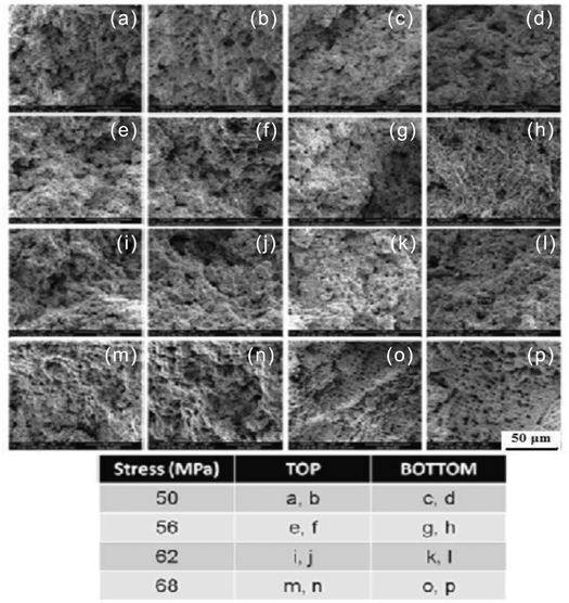
Fractograph of crept service exposed specimens (both top and bottom portion of the tube) tested at 870°C in the stress range of 52–68 MPa.
Quantification of creep cavities after rupture of service exposed reformer tubes
Population of voids (appearing grey) at various stresses and strains is shown in Figure 5. The population of void cavity on the creep ruptured surface was found to be nucleated either at grain boundary (GB) or at grain boundary triple point (GBTP) predominantly and also in the vicinity of other carbide particles. A similar kind of metallographic technique was employed to measure the extent of martensite at various strain reported elsewhere [12], which is already well established.
![Figure 5: Extent of creep cavity at various stresses and strains (a, c, e, g, i, k) – 50 MPa and (b, d, f, h, j, l) – 68 MPa for the top tube. True strain at (a) 1.187, (c) 0.897, (e) 0.626, (g) 0.525, (i) 0.398 and (k) 0.359. (b) 0.781, (d) 0.652, (f) 0.565, (h) 0.40, (j) 0.244 and (l) 0.149 [8].](/document/doi/10.1515/htmp-2014-0111/asset/graphic/htmp-2014-0111_figure5.gif)
Extent of creep cavity at various stresses and strains (a, c, e, g, i, k) – 50 MPa and (b, d, f, h, j, l) – 68 MPa for the top tube. True strain at (a) 1.187, (c) 0.897, (e) 0.626, (g) 0.525, (i) 0.398 and (k) 0.359. (b) 0.781, (d) 0.652, (f) 0.565, (h) 0.40, (j) 0.244 and (l) 0.149 [8].
It was found that the probability of GBTP cavitations [8] was almost three times that of GB voids (Figure 6) where the initial inclusion volume fraction in all the specimens remained unaltered. Void distribution at GB and GBTP was inhomogeneous in the deformed austenite dendrites. After nucleation of the voids, the voids would align themselves and grow under the influence of favourable tensile stress and plastic strain. Eventually the voids would join up leading to final rupture in the tertiary region of the creep curve.
![Figure 6: (a) Number of creep cavity formation at GB and at (b) GBTP as a function of strain for all stress levels for both the top and bottom tubes together [8].](/document/doi/10.1515/htmp-2014-0111/asset/graphic/htmp-2014-0111_figure6.jpg)
(a) Number of creep cavity formation at GB and at (b) GBTP as a function of strain for all stress levels for both the top and bottom tubes together [8].
Prediction of remnant life of the service exposed reformer tubes
It was clearly revealed in Figure 1 that creep cavitation or voids in the as received (uncrept) tubes were not present and so it is realistic to obtain a residual life of 10 years (Table 1, Figure 7) for both the top and bottom portions of the reformer tubes only if there is no deterioration or localised damage in any form in the material due to prolong service exposure. NRIM stress rupture data of similar grade of steel [10] have been super imposed on the stress rupture plots (Figure 7) for the sake of comparison with the accelerated creep rupture or stress rupture data and for estimation of residual life of the tubes in the present scope of work. Nevertheless, it was evaluated from Figure 7 that, at the design temperature of 920°C/13.46 MPa, a balance life of 7 years and 6 years for the top and bottom portions of the 11 years service exposed primary reformer tubes respectively would be possible (Table 1). This is true only when there is no localised damage of any form in the material, as revealed from non-destructive evaluation method of testing. Similar health check for safety and economical reasons of the operating tubes, in terms of residual life is required after a period of about two and a half years of further service life.
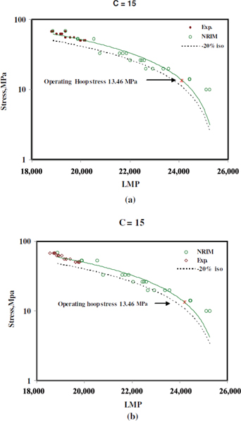
Stress vs LMP Plot for 11 years service exposed Reformer tube materials (a) top and (b) bottom for comparison with –20% NRIM standard data line.
Statistical analysis of creep cavity area for service exposed reformer tubes
Nucleation and growth of voids or creep cavities are responsible for creep damage. Nucleation is a random process and is deterministic, whereas growth of voids is probabilistic. The type and distribution of cavities during various stages of creep strain in a high temperature component is schematically represented in Figure 8. Most of the creep data reported for steels have focused only on experimental research with a view to examining the effect of microstructure on void formation. Void nucleation is strongly dependent upon the local stress-state and strain-state. It has been observed that over various test conditions, for the both top and bottom portions of tube, the normalised void area fraction
where a and b are Weibull parameter.
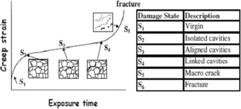
A schematic representation of the nature of damage evolution in material subjected to creep loading and the phases used to represent the same.
The probability of failure due to void area at various strain is calculated using eq. (7). From statistical point of view, the pattern of Weibull distribution (Figure 9) followed for analysing probability of rupture due to cavity or void area shifts with increase in true strain towards the higher population of void.
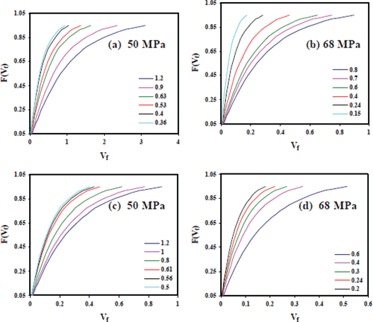
Probability distribution of void area fraction at 870°C/56 MPa: (a) top and (b) bottom portion of service exposed reformer tube, at various true strain.
Deterministic approach: CDM model for creep damage of service exposed reformer tubes
Kachanav [14] CDM model (K-model) has been used to estimate creep damage. The model is well established and has been applied to analysis of accumulation of creep strain data for 11 years service exposed reformer tube (both top and bottom portions) for different stresses at 870°C in the present investigation. Nucleation of voids/cavities being deterministic, the scatter band in damage estimation under identical test conditions can be easily estimated by carrying out a Monte Carlo Simulation. Similar simulation study was carried out on service exposed P22 grade of steel [15] and austenitic stainless steel [16].
According to Cane [17], a creep damage (ω) relationship can be established for estimating the creep life fraction already utilized with respect to time, t and at constant stress conditions:
where λ is creep damage tolerance factor
Strain rate accumulation can be estimated [14–16] during the entire tenure of creep life by introducing ω. Estimation of damage (ω) from eq. (5) is then made at the limiting conditions, (i.e. at ω = 0;t = 0 and ω = 1; t = tr) from the following equation [14–16]:
A and n are material constants. The value of ω can be calculated from eq. (9), as experimentally calculated (Exp) data as shown in Figure 10. Similar predictions on a recent work pertaining to service exposed P22 grade of steel [15] were made.
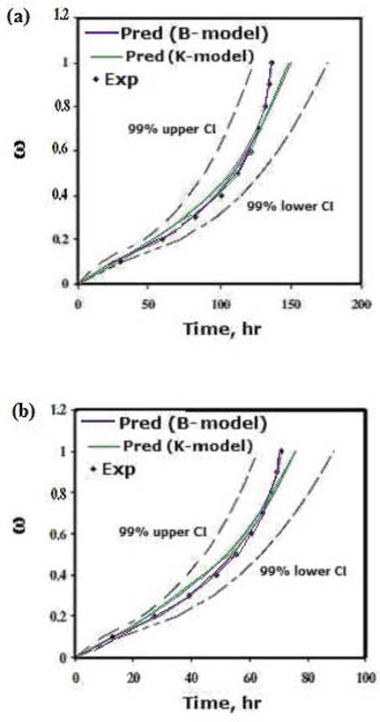
Comparison of the experimental and predicted values of mean time to reach a specified damage state by CDM (K-model) and B-model approach with relative confidence interval (CI) at 870°C/56 MPa: (a) top and (b) bottom portion of service exposed reformer tube.
Experimental data for estimating ω, agrees well with simulation-based CDM model for estimation of damage with scatter associated with it. This pertains to the sudden changes in creep damage in the tertiary region as well (Figure 10).
Stochastic approach: Markov process for creep damage of service exposed reformer tubes
Growth of voids/cracks is probabilistic. Cumulative damage process is the accumulation of voids and microcracks inside the material. Figure 8 gives a schematic representation of the various stages of nucleation and joining of voids/cavities leading to rupture at different levels of accumulation of strain. During creep, a virgin material goes through each of the stages represented in Figure 8, before rupture occurs. The process of accumulation of damage during creep depends only on its current state. Therefore, it was possible to simulate this by a Markov chain process [16, 21] which is defined as a stochastic process satisfying the following condition:
Similar study was carried out for an austenitic stainless steel and is reported and discussed in details in [16]. Sn represents nth event and the indices i, j, k, etc. represent the state number. The process of void growth is irreversible. In other words, if it is in state Si it cannot move to Sj where j < i. State 1 indicates the initial state with no damage and state b indicating the final damage state (rupture or failure state) or the absorbing state. Leckie and Hayhurst [20] have defined the initial distribution of the different damage levels at time t = 0, by a (1 × b) row vector po:
Probability of moving to state 3 and beyond is zero. Accumulation of creep damage in a material is represented by a transition matrix P [21, 22], (refer to Appendix for details).
All states in the transition matrix P are transient, except for state b (absorbing state). Bogdanoff and Krieger [22] had suggested a simple procedure for estimating these elements to simulate fatigue damage evolution. The same procedure [22] had been used in this work as B-model to predict creep damage evolution as a function of time.
Comparison of the experimental and predicted values of mean time to reach a specified damage state by CDM (K-model) as well as B-model approach with relative confidence interval (CI) of 99% at 870°C/56 MPa: (a) top and (b) bottom portion of service exposed reformer tube is revealed in Figure 10. This indicates or depicts that both the predictions are in close agreement with that of experimental data and can describe the sudden changes of damage associated with creep in the tertiary region as well.
Conclusions
Creep cavitation or voids were absent in the as received (uncrept) primary reformer tubes, but there was loss of tensile strength from room temperature to 870°C for the bottom portion of the tube due to ageing and overheating.
Experimental scatter was observed in creep deformation and creep strain rate curve at 870°C of service exposed material of both top and bottom portion of the reformer tube at various stress conditions. In spite of the fact that there was evidence of ductile dimples in top as well as bottom portion of the tube, mode of fracture mainly varied from ductile-quasi cleavage-brittle failure. This was probably responsible for experimental scatter.
From statistical point of view, the pattern of Weibull distribution followed for analysing probability of rupture due to cavity or void area shifts with increase in true strain towards the higher population of void.
Experimental data for estimating damage in the material agree well with simulation-based CDM model or K-model, for estimation of damage with scatter associated with it. This pertains to the sudden changes in creep damage in the tertiary region as well prediction of mean time to reach a specific damage state from CDM model as well as B-model are in close agreement with that of experimental data.
A residual life or remaining life of >10 years is estimated at the operating stress–temperature conditions of the top as well as bottom portion of the service exposed primary reformer tube.
At the design temperature of 920°C/13.46 MPa a residual/balance life of 7 years and 6 years for the top and bottom portions of the 11 years service exposed primary reformer tubes respectively would be realistic, only if there is absence of any form of localised damage in the material.
Acknowledgments
Authors would like to express their sincere thanks to Director, CSIR-NML, Jamshedpur, India, for permitting us to publish this piece of work.
Appendix
Stochastic approach: Markov process for assessing creep damage
In stochastic approach, a random variable W has been introduced to determine the probability transition matrix P in which W1,b is the time to failure at state b, given that the process begins in state 1.
The mean and the variance of W1,b are
where
The determination of pj and qj is given elsewhere [16]. Accumulation of creep damage in a material is represented by a transition matrix P [21, 22]:
All states in the transition matrix P are transient, except for state b (absorbing state). Bogdanoff and Krieger [22] have suggested a simple procedure for estimating these elements to simulate fatigue damage evolution. The same procedure [22] has been used in this work as B-model to predict creep damage evolution as a function of time.
References
[1] S.A. Jenabali Jahromi and M. Naghikhan, Failure analysis of HP40-NB modified primary reformer tube of ammonia plant. Iran J Sci Technol Trans B Eng 2004;28:269–71.Suche in Google Scholar
[2] A.K. Ray, S.K Sinha, Y.N. Tiwari, J. Swaminathan, G. Das, S. Chaudhuri and R. Singh, et al. Analysis of failed reformer tubes. Eng Fail Anal 2003;10:351–62.10.1016/S1350-6307(02)00029-8Suche in Google Scholar
[3] D. Knowles, K. Buchanan, M. Kral, Condition assessment strategies in centrifugally cast HP steam reformer tube alloys. In: ECCC Creep Conference, Zurich, 2009.Suche in Google Scholar
[4] F. Garafalo, R.W. Whitmore, W.F, Domisand F., von Gemmingen. Creep and creep-rupture relationships in an austenitic stainless steel. Trans Metall AIME 1961;221:310–19.Suche in Google Scholar
[5] K. Kimura, H. Kushima, F. Abe and K. Yagi,Inherent creep strength and long term creep strength properties of ferric steels. Mater Sci Eng A 1997;234–236:1079–82.10.1016/S0921-5093(97)00345-6Suche in Google Scholar
[6] K. Ray, S. Kumar, G. Krishna, M. Gunjan, B. Goswami and S.C. Bose, Microstructural studies and remnant life assessment of eleven years service exposed reformer tube. Mater Sci Eng A 2011;529:102–12.10.1016/j.msea.2011.09.003Suche in Google Scholar
[7] T.H. Toft and R.A. Marsden, The structure and properties of 1% cr 0.5% mo steel after twenty years service in cegb power station. Conference on structural processes in Creep, London, 1963:275.Suche in Google Scholar
[8] A. Das, N. Roy and A.K. Ray, Stress induced creep cavity. Mater Sci Eng A 2014;598:28–33.10.1016/j.msea.2013.12.097Suche in Google Scholar
[9] C.J. Moss, P. Barrien, C.J. Moss, A. Walczynski. Life management of refinery furnace tubing. Int J Pres Ves Pip 2000;77:105–12.10.1016/S0308-0161(99)00090-3Suche in Google Scholar
[10] NRIM creep data sheet No. 38A. Data sheets on the elevated temperature properties of centrifugally cast tubes and cast block of 25Cr35Ni0.4C steel for reformer furnaces (SCH 24).Suche in Google Scholar
[11] N. Roy, R.N. Ghosh, and S.C. Bose, A Stochastic model for evolution of creep damage in engineering material. Trans Indian Inst Met 2010;63:665–9.10.1007/s12666-010-0101-2Suche in Google Scholar
[12] A. Das. Martensite–void interaction. Scripta Mater 2013;68:514–17.10.1016/j.scriptamat.2012.11.039Suche in Google Scholar
[13] W. Weibull, A statistical distribution function of wide applicability. ASME J Appl Mech 1951;18:293–7.10.1115/1.4010337Suche in Google Scholar
[14] L.M. Kachanov, Time to failure under creep conditions. Izv ANSSSR OTN 1958;8:26–31.Suche in Google Scholar
[15] Roy, S. Bagui, J. K. Sahu, A.K. Ray. Creep characterization and damage assessment of long term service exposed P-22 grade of steel. Mater Sci Eng A 2013;560:802–10.10.1016/j.msea.2012.10.039Suche in Google Scholar
[16] N. Roy, S.C. Bose and R.N. Ghosh, Stochastic aspects of evolution of creep damage in austenitic stainless steel. Mater Sci Eng A 2010;527:4810–17.10.1016/j.msea.2010.04.013Suche in Google Scholar
[17] B.J. Cane, Estimating the remnant creep life of power plant components. High Temp Techno 1983;1:215–28.10.1080/02619180.1983.11753211Suche in Google Scholar
[18] M.F Ashby, B.F. Dyson, et al., editors. Use of CDM in materials modeling and component creep. Advances in fracture research. Oxford: Pergamon Press, 1984:3.10.1016/B978-1-4832-8440-8.50017-XSuche in Google Scholar
[19] F. Dyson and T.B. Gibbons, Tertiary creep in nickel base superalloys: analysis of experimental data and theoretical synthesis. Acta Metall 1987;35:2355–69.10.1016/0001-6160(87)90083-6Suche in Google Scholar
[20] F.A. Leckie and D.R. Hayhurst. Constitutive equations for creep rupture. Acta Metall 1977;25:1059–70.10.1016/0001-6160(77)90135-3Suche in Google Scholar
[21] W.J. Stewart. Introduction to the numerical solution of markov chains. Princeton, NJ: Princeton University Press, 1994.Suche in Google Scholar
[22] J.L. Bogdanoff, W. Krieger, A New cumulative damage model: Part 2 ASME. J Appl Mech. 1978;45:251–7.10.1115/1.3424283Suche in Google Scholar
©2015 by De Gruyter
This article is distributed under the terms of the Creative Commons Attribution Non-Commercial License, which permits unrestricted non-commercial use, distribution, and reproduction in any medium, provided the original work is properly cited.
Artikel in diesem Heft
- Frontmatter
- The Influence of the Induced Ferrite and Precipitates of Ti-bearing Steel on the Ductility of Continuous Casting Slab
- Study on Evolution of Ti-containing Intermetallic Compounds in Alloy 2618-Ti during Homogenization
- The Effects of Different P2O5 Content and Basicity on Phosphorus Enrichment in the CaO-SiO2-FetO-P2O5 Slag System
- Dry Sliding Wear Behaviours of Valve Seat Inserts Produced from High Chromium White Iron
- A Characterization for the Hot Flow Behaviors of As-extruded 7050 Aluminum Alloy
- A Characterization of Hot Flow Behaviors Involving Different Softening Mechanisms by ANN for As-Forged Ti-10V-2Fe-3Al Alloy
- Effect of Microwave Heating Conditions on the Preparation of High Surface Area Activated Carbon from Waste Bamboo
- Laboratory Study on Oxide Inclusions in High-Strength Low-Alloyed Steel Refined by Slag with Basicity 2–5
- Processing and Characterization of CrB2-Based Novel Composites
- Dispersion of Particles in the Emulsion by the Electric Current
- Description of Grain Refinement by Dynamic Recrystallization Under Hot Compressions for As-Extruded 3Cr20Ni10W2 Heat-Resistant Alloy
- Identification of Stable Processing Parameters in Ti–6Al–4V Alloy from a Wide Temperature Range Across β Transus and a Large Strain Rate Range
- Life Estimation and Creep Damage Quantification of Service Exposed Reformer Tube