
Dynamic response of functionally graded plate under harmonic load with variable gradient parameters
-
Jianhui Tian
 ,
Hongrui Zhang
,
Hongrui Zhang

Abstract
This article used the strip element method to study the dynamics problems of the functionally graded plate with variable gradient parameters under the harmonic loads. The dynamic model of the functionally graded plate is established by using the strip element method, the rationality and accuracy of the theoretical results are verified by finite element method, and the displacement response under different gradient parameters is also calculated. The results show that under the different gradient parameters, the displacement varies harmonically with time, and with the increase of gradient parameters, the fluctuation period of displacement with time increases continuously, and the displacement peak also gradually increases. The displacement along the thickness direction also shows the harmonic form. Through comparison, it is found that the gradient parameters have a greater impact on the dynamic response for the functionally graded plate; with the increase in the gradient parameters, the displacement response also increases, but the displacement response trend slows down.
1 Introduction
Due to the high specific strength and specific stiffness, and easy design, functionally graded materials (FGMs) can work under some extreme environmental conditions and are widely used in aerospace, biomedicine, petrochemical, heavy industry, and other fields [1,2,3]. With the development of FGMs, the research on the dynamic characteristics of FGMs becomes more and more important. In the process of dynamics research, at present, in the field of traditional FGMs research, linear parameters are generally used, which results in certain limitations in practical applications. Therefore, the dynamics of FGMs with variable gradient parameters is extremely critical and important.
Compared with other composite materials, FGMs have better mechanical properties. The key researches mainly focus on vibration, shock, and dynamic response under different external conditions and different boundary conditions by using different methods, such as theoretical solutions, numerical calculations, or experiments. Shariyat et al. [4] used finite element method and iterative algorithm to study the dynamic stress, displacement distribution, hygrothermal elastic wave propagation, and reflection response of a functionally graded hollow sphere under thermomechanical shock. Hao et al. [5] studied the nonlinear forced vibration and natural frequency of a double-bent flat shell with a rectangular sandwich FGM and verified its effectiveness using numerical simulation methods. Gupta and Talha [6] focused on the structural characteristics of FGMs plates and shells under different boundaries and environmental conditions under thermo-electromechanical loads. Bakhtiari and Kheradpisheh [7] studied the transient response of an inflatable multilayer hollow functionally graded cylinder with interlayer adhesion defects under load. This structure is widely used in aerospace structures. Bozyigit et al. [8] applied the theory of univariate shear deformation to the analysis of the free vibration and harmonious response of the multi-layer frame model considering the basic flexibility. Aris and Ahmadi [9] studied the nonlinear vibration and resonance analysis of truncated gradient tapered shells under harmonic excitation. Parandvar and Farid [10] established a nonlinear finite element model of the dynamic response of a FGM plate under thermal, static, and harmonic loads and studied the effect of initial conditions and static pressure on the dynamic response of the system. Najarzadeh et al. [11,12] studied the free vibration of thin plates under arbitrary load using the boundary element method. Parida et al. [13] used the finite element method to perform dynamic analysis on the simply supported beam structure and studied the effect of temperature as a function of dynamic parameters on the mechanical properties. Guo et al. [14] analyzed the modes of simply supported plates with uniform thickness and stepped thickness by using a dynamic shape function. Using a dynamic stiffness method (DSM), Kumar and Jana [15] studied the free vibration characteristics of rectangular FGM thin plates with S-FGM and E-FGM characteristics along the thickness direction, and they studied the free vibration characteristics of functionally gradient rectangular plate using DSM [16].
For functionally graded plates with variable gradient parameters, previous research work has involved the study of the thermal conduction of functionally graded plates with variable gradient parameters under heat source load [17], but the research on the dynamic performance of variable gradient parameters has not been carried out, so based on the strip element method, fixed boundary conditions are applied to study the dynamic response of functionally graded plates with variable gradient parameters. In addition, Karamia et al. [18] studied the influence of various boundary conditions and found that for all boundaries. Dhital et al. [19] used the properties of two materials to smoothly transition from one material to another for reducing thermal stress, residual stress, and stress concentration factor. These studies are very helpful for the development of the research on functionally graded plates with variable gradient parameters. And Liu et al. [20] verified the correctness of the strip element method. However, the study of functionally graded plates with variable gradient parameters under harmonic load has not been mentioned. In this article, the variable gradient parameter model will be established on the basis of the strip element method to calculate the displacement response of the functionally gradient plate under different gradient parameters and verify its rationality and accuracy, this work provides a new way for the variable gradient parameter model.
2 Establishment of dynamic model
2.1 Dynamic theory model
When studying the dynamic performance of a functionally graded plate, as shown in Figure 1, the domain is defined by D g = (x, z), in which x ∈ (−∞, +∞), z ∈ (0, H), and D p ∈ D g , D p are composed of boundaries B 1, B 2, B 3, and B 4. Since the functionally graded plate is isotropic in the x–y plane and the y-direction is infinite, simplifying the problem to the two-dimension relation with x and z, there are only two displacement components u and v in x-direction and z-direction, respectively.
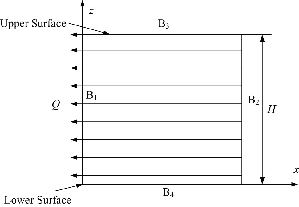
Functionally graded plate discrete model.
Without considering the internal damping of the functionally graded plate, it is assumed that the dynamic control equation of the functionally graded plate in matrix form as
where M is the mass matrix, U is the displacement vector, L T is the differential operator matrix, σ is the stress vector, and Q is the load vector.
2.2 System equation
The relationship between strain and displacement in matrix form is
where ε is the vector of the strain, defined as
The vector form of the displacement is
where u and v are the x-direction and z-direction displacements, respectively.
The differential operator matrix is
Simplify the differential operator matrix to
where L x , L z is a constant matrix
The relationship between stress and strain in matrix form is
where the vector form of stress is
The stiffness coefficient matrix is
Transforming the equation (1) could obtain the motion balance equation in the form of displacement
where
and D xx , D xz , and D zz could be calculated
Assuming boundary stress form as
when x is a constant, the stress acting on the x plane can be expressed as
when z is a constant, the stress acting on the z-plane can be expressed as
where
3 Dynamic theory of variable gradient parameter strip element method
3.1 Establishment of the theoretical model of variable gradient parameters
In the functionally graded plate, the volume fraction of ZrO2 is assumed to be
where a, b, r, and p is the gradient parameters and z is the coordinate thickness.
In this calculation model, gradient parameters are a = 1, b = 0, and gradient parameter p is a variable parameter from 0 to positive infinity. The volume fraction of ceramics in the model changes with the gradient value. When the gradient parameter p approaches infinite, the volume fraction of ceramics is close to zero, and when the gradient parameter p approaches zero, the volume fraction of ceramics is close to 1. Density, Poisson’s ratio and the elastic modulus of the functionally graded plate all depend on the volume fraction of ceramics. Different gradient parameters correspond to the volume fraction of ceramics in the direction of thickness as shown in Figure 2.
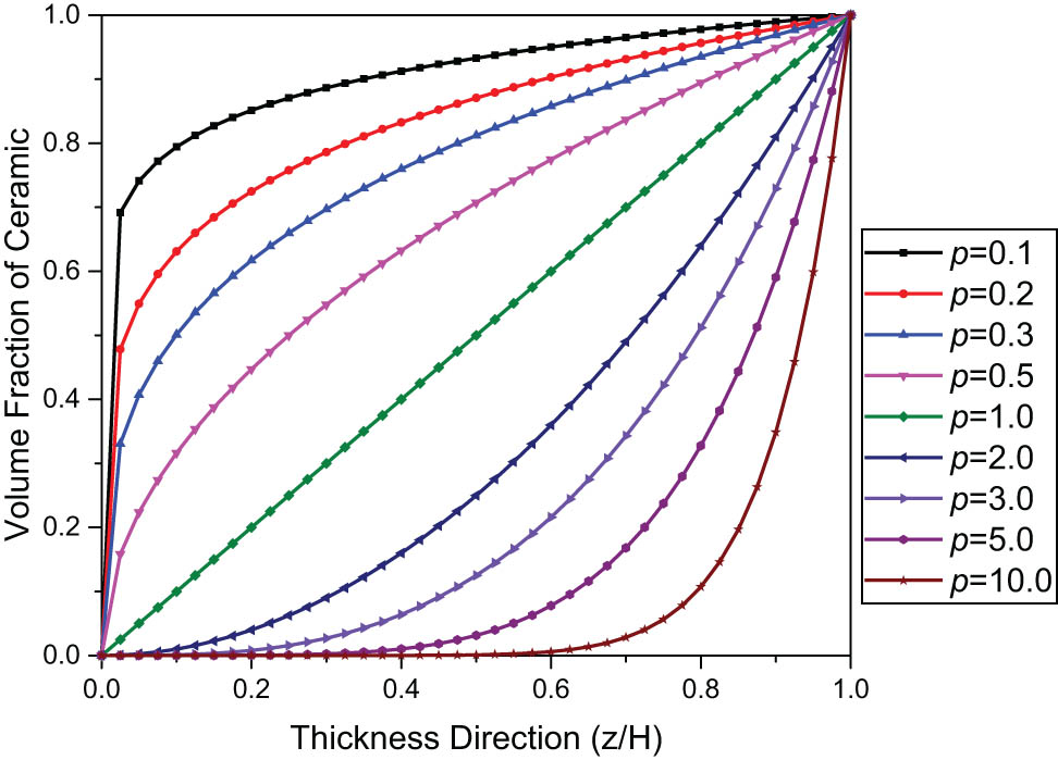
Volume fraction of ceramics under different gradient parameters.
The functionally graded plate is composed of ZrO2 and Ti–6Al–4V, and its material properties are shown in Table 1.
Material properties of ZrO2 and Ti–6Al–4V
| Material | Density | Elastic modulus | Poisson ratio |
|---|---|---|---|
| ρ (kg m−3) | E(Pa) | ||
| ZrO2 | 5,331 | 1.1 × 10¹¹ | 0.25 |
| Ti–6Al–4V | 4,420 | 3.5 × 10¹¹ | 0.32 |
As the volume fraction in the functionally graded plate changes, the density of the model also changes accordingly. The density in the model is assumed to be
where the ρ C is the density of ZrO2, ρ M is the density of Ti–6Al–4V.
Similarly, the elastic modulus of the functionally graded plate changes as
where E C is the elastic modulus of ZrO2 and E M is the elastic modulus of Ti–6Al–4V.
The variation of density corresponding to different gradient parameters in the thickness direction is shown in Figure 3. The change law of elastic modulus is consistent with the change law of the mass density.
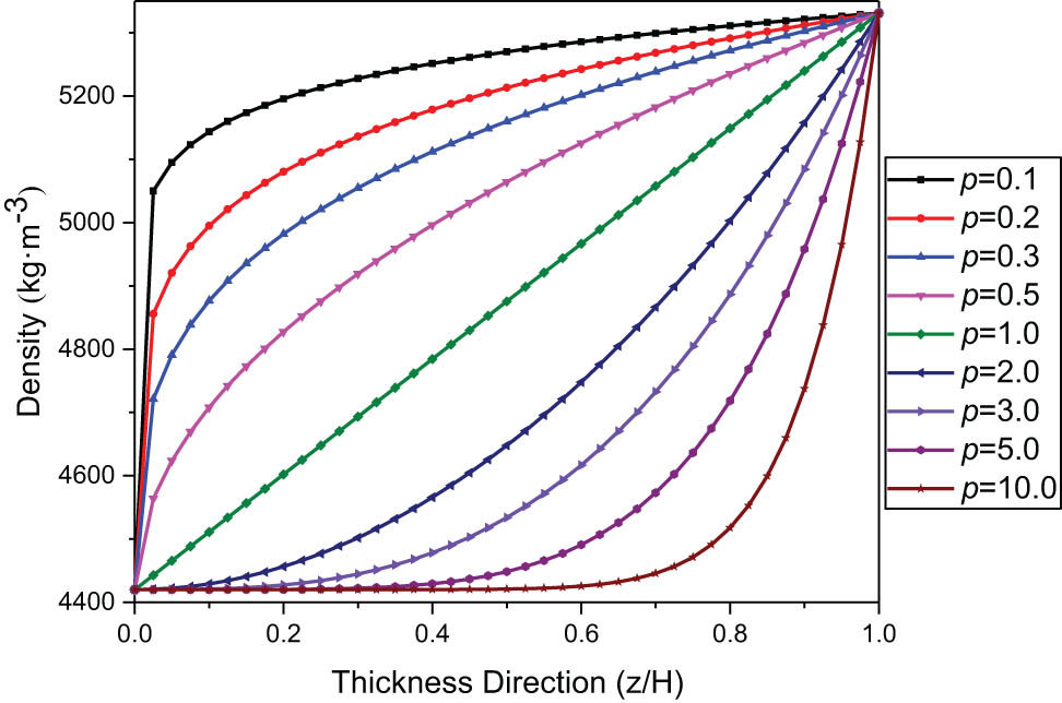
Density of functionally graded plates varies with gradient parameters.
3.2 Variable gradient parameter strip element method theory
Divide the domain D g into N strip elements, assuming that the displacement field of the element is
where V(x) is the displacement vector, N(z) is the shape function matrix, t is the time, and ω is the angular frequency.
where the I is the identity matrix, which
Assume the form of the applied harmonic external load is
where
According to the principle of virtual work, we could obtain
Solve the approximate differential set of a set of elements
where
in the mass matrix, I is a 2 × 2 identity matrix.
The obtained element equations are extended to the domain D g to obtain the approximate differential equations
The subscript g represents the matrix or vector in the whole domain, and the matrix
Equation (35) represents a set of second-order differential equations with constant coefficients that can be accurately solved. Assuming the form of displacement and load is
where k is the wave number.
Substituting equations (36) and (37) into equation (35) could obtain
where P g is the amplitude vector of the external force acting on the boundary node line.
For the given P g , the characteristic equation could be obtained:
For a given ω, equation (39) can be transformed into a standard characteristic equation:
Solving equation (41) can get 2m(m = 6N − 2(N − 1) = 4N + 2) eigenvalues k j (1…2m), if the upper part of the jth eigenvectors corresponding to d g is represented by ϕ j , then there is
According to the mode superposition method, the displacement of the x-direction can be written as the superposition of all eigenvectors
where C j is the undetermined coefficient, and equation (43) is a basic solution system in the D g domain. The constant vector C can be determined from the boundary B 1, B 2 to obtain a special solution of the problem domain D p . There are m nodes and 2m boundary conditions on the boundary B 1, B 2, respectively, resulting in 2m constants C j .
According to equation (43), the constant vector C can be expressed as the displacement vector of the node on the boundary B 1, B 2
where
where B
1 is the left boundary, and B
2 is the right boundary. In equation (45), u
i
and v
i
represent the displacements in the z-direction and the x-direction at the point i on the boundaries B
1 and B
2, respectively. In equation (47),
3.3 Application of boundary conditions
Using equation (18), at any point of x is a constant, the stress vector in one element is
where
and
where
Assemble matrix R 1, R 2 into the overall unit matrix and get the stress vector of the nodal line as
Simultaneous equations (43)–(43) could obtain
where
where K is the stiffness matrix. Equation (54) gives the relationship between stress and displacement at the left and right boundaries. For a given R bg , V bg could be calculated by equation (54), and V g can be calculated from equations (43) and (44). The global displacement in the time domain can be solved by equation (25).
3.4 Application of the dynamic strip method under simple harmonic load
The thickness of the functionally graded plate along the z direction is H = 90, and it is divided into 10-layer elements. Within the boundary formed by B 1, B 2, B 3, and B 4, the length of the functionally graded plate along the x-direction is x = H = 90. Harmonic load action time t = 2 s. The surface materials of the first layer and the tenth layer of this material are ZrO2 and Ti–6Al–4V, respectively, and the properties of the intermediate material change continuously along the thickness direction.
The amplitude of the applied harmonic load
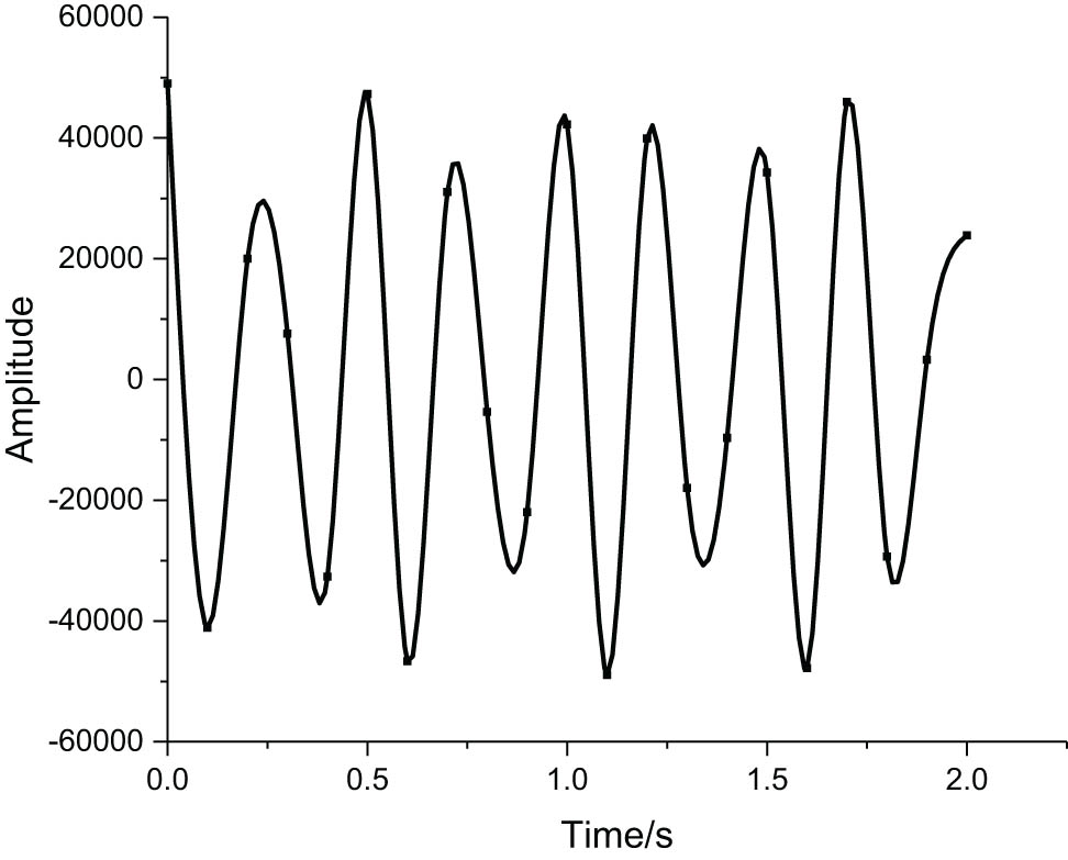
Harmonic load forms.
4 Results and discussion
Before the output of the theoretical results, the rationality and accuracy of the theoretical results need to be verified. For the theoretical in this article, further finite element simulation is needed to verify its accuracy and correctness. The study of functionally graded plates with variable gradient parameters shows that when the gradient parameters tend to infinity, the volume fraction of metal materials in functionally graded plates tends to 1. Therefore, the displacement response of pure metal material under harmonic loading is analyzed by the finite element method, and the results are in agreement with the strip element method (Figure 5).
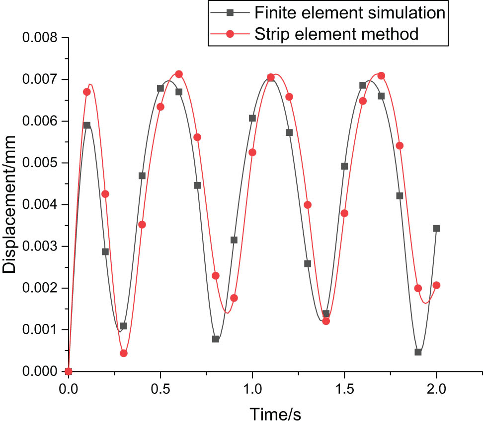
Verification of strip element method results and finite element results.
According to the displacement form of the strip element method, the law of the overall displacement of the functionally graded plate with time at z = 0 in the lower surface, gradient parameters p = 0.5, p = 1, p = 2, p = 5, and p = 10 are calculated as shown in Figure 6 under the harmonic load. It can be obtained that the overall displacement of the functionally gradient plate under the action of harmonic load presents sinusoidal fluctuation with time. Under the different gradient parameters, the displacement is in the form of simple harmonic motion with time, and with the increase of gradient parameters, the fluctuation period of displacement with time increases continuously, and the displacement peak also gradually increases, because the metal composition of the functionally gradient plate increases with the increase of gradient parameters, and the plasticity of metal is greater than that of ceramic.
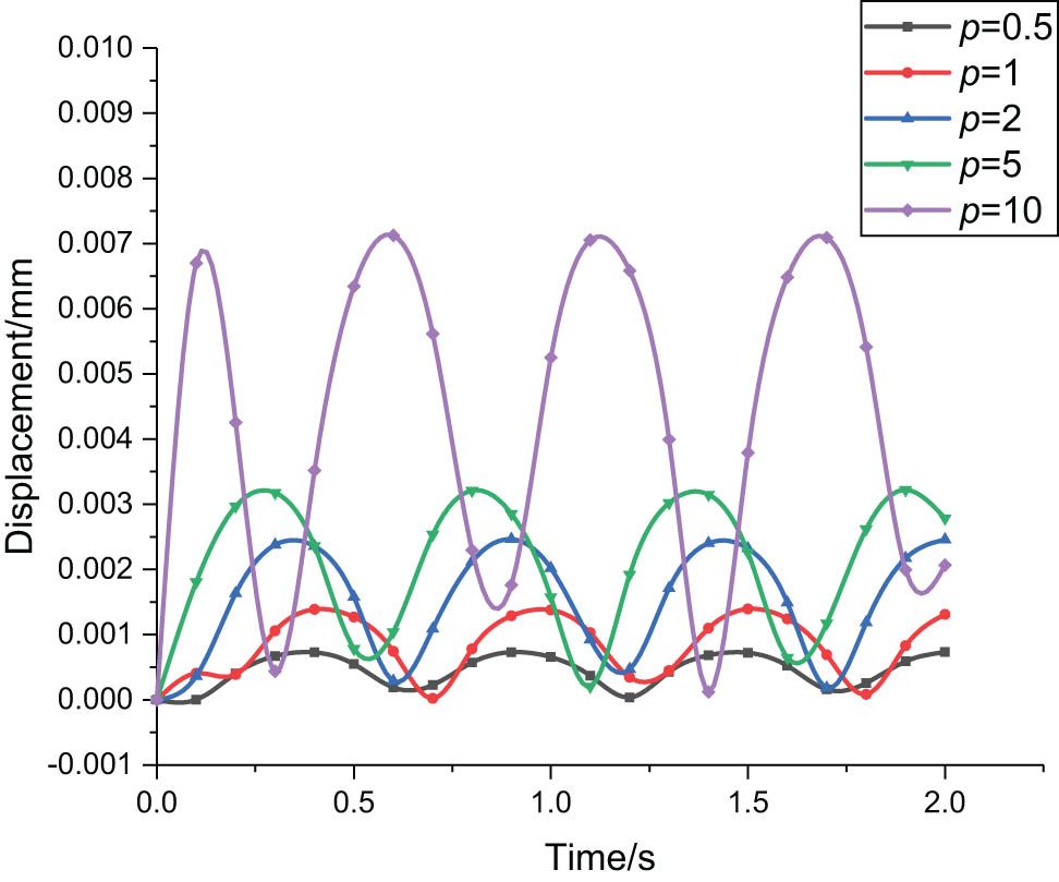
Overall displacement changes with time under different gradient parameters at z = 0.
Figure 7 shows the variation law of displacement with gradient parameters at t = 0.2 s and t = 1.3 s. It can be found that the displacement of the functionally graded plate increases with the gradient parameters, but the increasing trend first increases and then decreases.
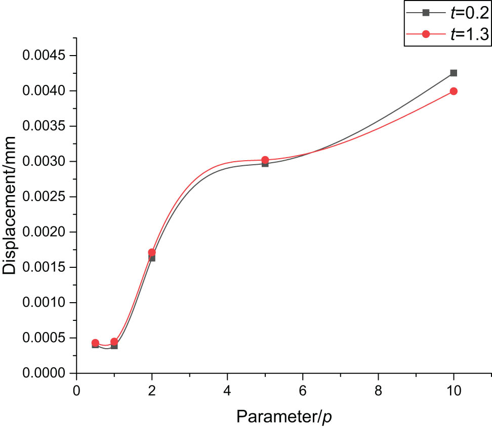
Overall displacement changes with the gradient parameter.
Figure 8(a)–(c) respectively shows at the gradient parameters p 1 = 0.5, p 2 = 1, p 3 = 2, p 4 = 5, p 5 = 10 of the functionally graded plate as the displacement changes along the thickness at x = 0 mm, x = 45 mm, and x = 90 mm. It can be obtained that the displacements along the thickness direction at different positions of x are in harmonic form within the boundary. The peak displacement appears between x = 20 and x = 80. The displacement peak value is different under different gradient parameters. As the gradient parameter increases, the displacement peak value gradually increases and the displacement phase also increases.
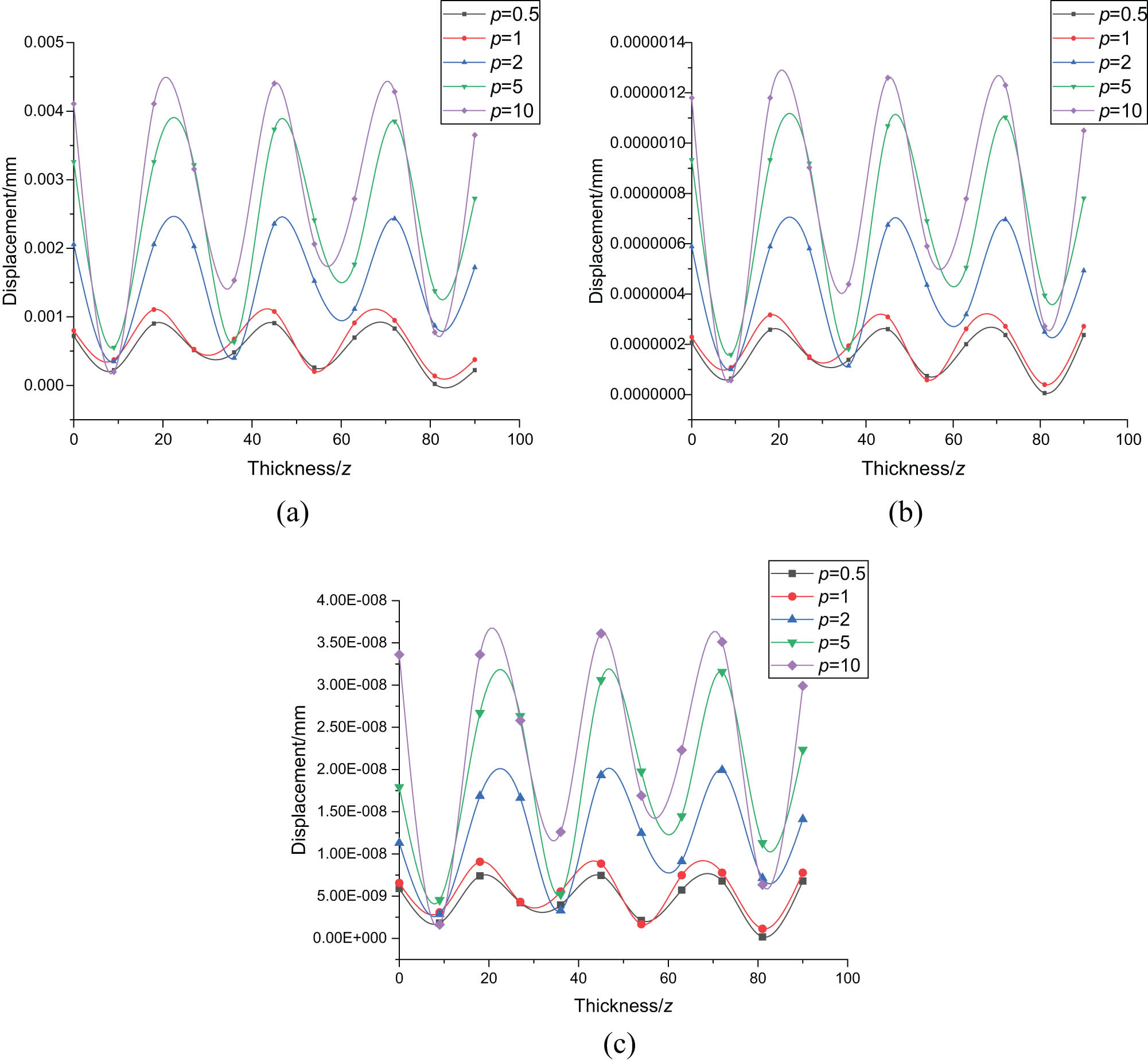
Displacement changes under different gradient parameters along the thickness with different x positions. (a) x = 0, (b) x = 45, and (c) x = 90.
Figure 9(a)–(c) respectively shows the displacement of the upper surface, middle surface, and lower surface of the functionally graded plate with gradient parameters at x = 10 mm, x = 45 mm, and x = 90 mm. It can be obtained that the displacement of the upper surface, the middle surface, and the lower surface is related to the gradient parameters and increases with the increase in the gradient parameters. With the increase in the gradient parameters, the volume fraction of metal in the functionally graded plate increases, and the plastic deformation capacity of metals is higher than that of ceramics. Therefore, as the gradient parameters increase, the displacement increases gradually.
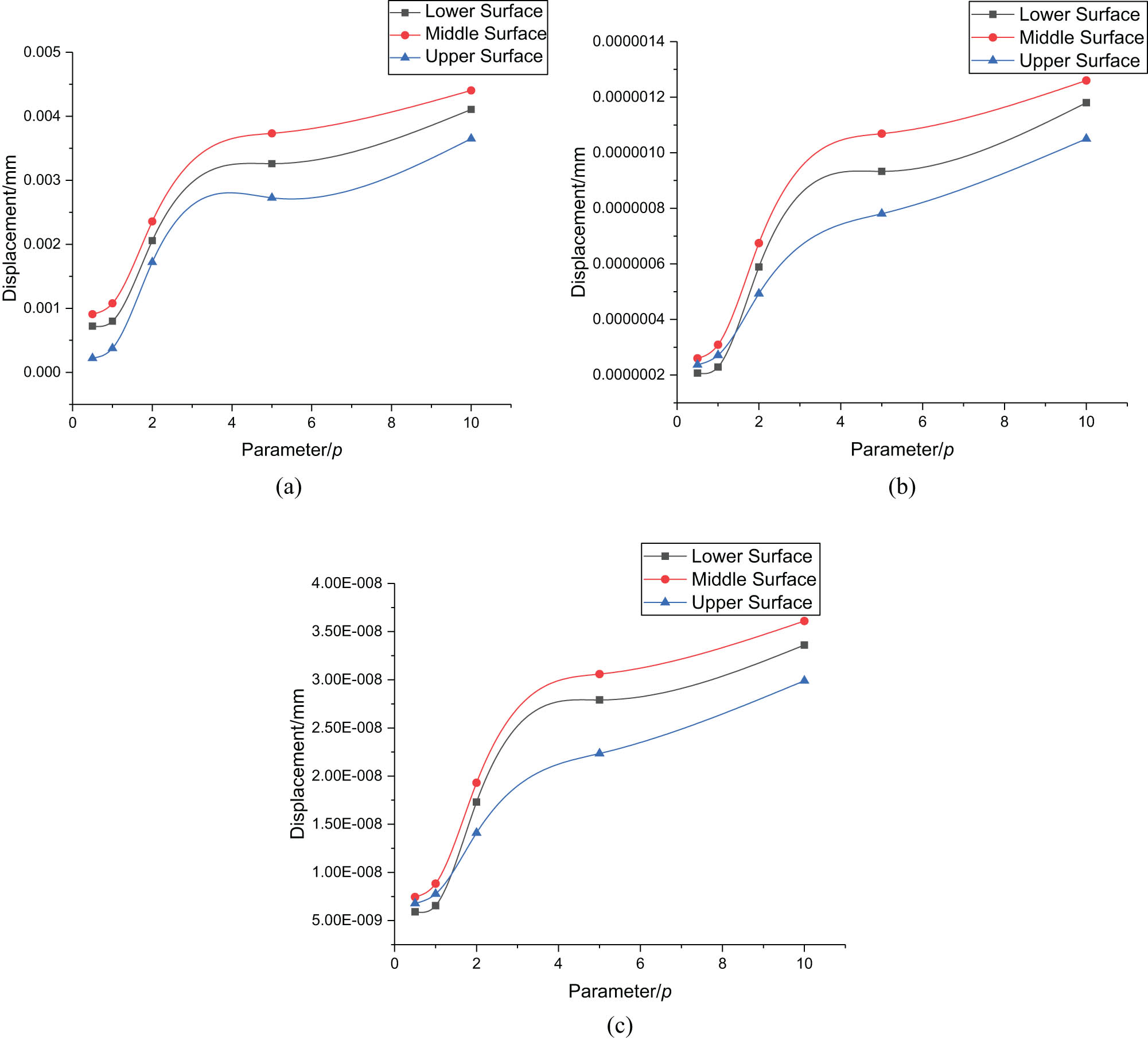
The upper, middle, and lower surface displacement changes with gradient parameters with different x positions. (a) x = 0, (b) x = 45, and (c) x = 90.
Figure 10(a) and (b), respectively, shows the variation of displacement along the x-direction on the upper, middle, and lower surfaces of the functionally graded plate at p = 0.5 and p = 2. It can be seen that the displacement of the functionally graded plate has a faster downward trend along the x-direction and gradually tends to zero on the boundary. Among them, the displacement when the displacement p = 0.5 is smaller than that when p = 2, and the displacement is maximum on the middle surface.
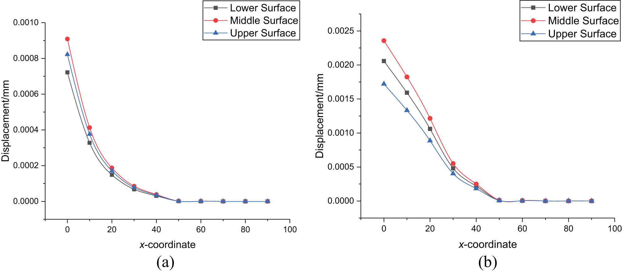
The upper, middle, and lower surface displacement changes along the x-direction with different parameters. (a) p = 0.5 and (b) p = 2.
5 Conclusion
The strip element method is first used to study the dynamics of functionally graded plates with variable gradient parameters under harmonic loads, and useful conclusions are obtained:
Under the different gradient parameters, the displacement varies harmonically with time, and with the increase of gradient parameters, the fluctuation period of displacement with time increases continuously, and the displacement peak also gradually increases.
Under the fixed boundary conditions, the displacement of the functionally graded plate along the thickness direction shows the harmonic form.
By comparing the displacement at different positions for gradient parameters, as the gradient parameters increase, the peak displacement of the functionally graded plate increases, but the trend of displacement changes decreases.
The displacement perpendicular to the load direction gradually tends to zero along the x-axis, and the displacement peak appears on the middle surface of the functionally graded plate.
Acknowledgments
The research is supported by the National Natural Science Foundation of China (No. 11302159), the Principal Foundation of Xi’an Technological University (No. XGPY200213), Basic Research Plan of Natural Science in Shannxi Province (No. 2021JQ-650), and Scientific Research Program Funded by Shaanxi Provincial Education Department (No. 19JK0412).
-
Conflict of interest: The authors state no conflict of interest.
References
[1] Fujita K, Furukawa H, Yamanaka M, Niino M. Solar excited laser using FGM concept for space energy network. Mater Sci Forum. 2003;423–425:807–12.10.4028/www.scientific.net/MSF.423-425.807Search in Google Scholar
[2] Obata Y, Takeuchi K, Kawazoe M, Kanayama K. Design of functionally graded wood-based board for floor heating system with higher energy efficiency. Mater Sci Forum. 2003;423–425:819–24.10.4028/www.scientific.net/MSF.423-425.819Search in Google Scholar
[3] Uemura S. The activities of FGM on new application. Mater Sci Forum. 2003;423–425:1–10.10.4028/www.scientific.net/MSF.423-425.1Search in Google Scholar
[4] Shariyat M, Jahanshahi S, Rahimi H. Nonlinear hermitian generalized hygrothermoelastic stress and wave propagation analyses of thick FGM spheres exhibiting temperature, moisture, and strain-rate material dependencies. Composite Struct. 2019;229:111364.10.1016/j.compstruct.2019.111364Search in Google Scholar
[5] Hao Y, Li Z, Zhang W, Li S, Yao M. Vibration of functionally graded sandwich doubly curved shells using improved shear deformation theory. Sci China Technol Sci. 2018;61(6):791–808.10.1007/s11431-016-9097-7Search in Google Scholar
[6] Gupta A, Talha M. Recent development in modeling and analysis of functionally graded materials and structures. Prog Aerosp Sci. 2015;79:1–14.10.1016/j.paerosci.2015.07.001Search in Google Scholar
[7] Bakhtiari M, Kheradpisheh M. Dynamics behavior and imperfection sensitivity of a Fluid-filled multilayered FGM cylindrical structure. Int J Mech Sci. 2020;176:105425.10.1016/j.ijmecsci.2020.105425Search in Google Scholar
[8] Bozyigit B, Yesilce Y, Wahab MA. Single variable shear deformation theory for free vibration and harmonic response of frames on flexible foundation. Eng Struct. 2020;208:110268.10.1016/j.engstruct.2020.110268Search in Google Scholar
[9] Aris H, Ahmadi H. Nonlinear vibration analysis of FGM truncated conical shells subjected to harmonic excitation in thermal environment. Mech Res Commun. 2020;104:103499.10.1016/j.mechrescom.2020.103499Search in Google Scholar
[10] Parandvar H, Farid M. Large amplitude vibration of FGM plates in thermal environment subjected to simultaneously static pressure and harmonic force using multimodal FEM. Composite Struct. 2016;141:163–71.10.1016/j.compstruct.2016.01.044Search in Google Scholar
[11] Najarzadeh L, Movahedian B, Azhari M. Free vibration and buckling analysis of thin plates subjected to high gradients stresses using the combination of finite strip and boundary element methods. Thin-Walled Struct. 2018;123:36–47.10.1016/j.tws.2017.11.015Search in Google Scholar
[12] Najarzadeh L, Movahedian B, Azhari M. Stability analysis of the thin plates with arbitrary shapes subjected to non-uniform stress fields using boundary element and radial integration methods. Eng Anal Bound Elem. 2018;87:111–21.10.1016/j.enganabound.2017.11.010Search in Google Scholar
[13] Parida SP, Jena PC, Dash. RR. FGM beam analysis in dynamical and thermal surroundings using finite element method. Mater Today. 2019;18:3676–82.10.1016/j.matpr.2019.07.301Search in Google Scholar
[14] Guo SJ, Keane AJ, Moshrefi-Torbati M. Vibration analysis of stepped thickness plates. J Sound Vib. 1997;204(4):645–57.10.1006/jsvi.1997.0955Search in Google Scholar
[15] Kumar S, Jana P. Application of dynamic stiffness method for accurate free vibration analysis of sigmoid and exponential functionally graded rectangular plates. Int J Mech Sci. 2019;163:105105.10.1016/j.ijmecsci.2019.105105Search in Google Scholar
[16] Kumar S, Ranjan V, Jana P. Free vibration analysis of thin functionally graded rectangular plates using the dynamic stiffness method. Composite Struct. 2018;197:39–53.10.1016/j.compstruct.2018.04.085Search in Google Scholar
[17] Tian J, Zhang H, Sun J. Study on heat conduction of functionally graded plate with the variable gradient parameters under the H(t) heat source. J Therm Stresses. 2020;43(6):724–38.10.1080/01495739.2020.1742623Search in Google Scholar
[18] Karamia B, Janghorban M, Rabczuk T. Dynamics of two-dimensional functionally graded tapered timoshenko nanobeam in thermal environment using nonlocal strain gradient theory. Compos Part B. 2020;182:107622.10.1016/j.compositesb.2019.107622Search in Google Scholar
[19] Dhital S, Rokaya A, Kaizer MR, Zhang Y, Kim J. Accurate and efficient thermal stress analyses of functionally graded solids using incompatible graded finite elements. Composite Struct. 2019;222:110909.10.1016/j.compstruct.2019.110909Search in Google Scholar PubMed PubMed Central
[20] Liu G, Xi Z, Horie Y. Elastic waves in an-isotropic laminates. Appl Mech Rev. 2001;56(2):B23.10.1115/1.1553437Search in Google Scholar
© 2022 Jianhui Tian et al., published by De Gruyter
This work is licensed under the Creative Commons Attribution 4.0 International License.
Articles in the same Issue
- Regular Articles
- Experimental investigations of a novel pressure microfoam preparation device for dust removal
- Influence of hydrothermal aging on the mechanical performance of foam core sandwich panels subjected to low-velocity impact
- Experimental study on surface wrapping strengthening of EPS particles and its concrete performance
- Modification of mechanical properties of Shanghai clayey soil with expanded polystyrene
- A new EPS beads strengthening technology and its influences on axial compressive properties of concrete
- A novel superabsorbent material based on soybean straw: Synthesis and characterization
- Use of line laser scanning thermography for the defect detection and evaluation of composite material
- Research on back analysis of meso-parameters of hydraulic cemented sand and gravel based on Box-Behnken design response surface
- Hot deformation behavior and microstructure of a 0.5 wt% graphene nanoplatelet reinforced aluminum composite
- Analysis of electromagnetic characteristics of the proposed composite four-rail electromagnetic launcher
- Preparation and characterization of a graphene hybridizing polyurethane damping composite
- Effects of layup parameters and interference value on the performance of CFRP–metal interference fit joints
- Vibration and noise reduction of pipelines using shape memory alloy
- Finite element analysis of behavior and ultimate strength of composite column
- Dynamic response of functionally graded plate under harmonic load with variable gradient parameters
- Deformation behavior of rubber composite based on FEA and experimental verification
- Effects of Z-pin on moisture absorption property and damage mode under flexural load for carbon fiber composite
- Design and testing of a smart rubber stave for marine water-lubricated bearings
- Study of carbon nano-modifier of fly ash in cement concrete mixtures of civil engineering
- Analysis of multiple impact tests’ damage to three-dimensional four-directional braided composites
- Theoretical analysis of aluminum honeycomb sandwich panel supported by reinforced concrete wall under low-speed impact load
- Effects of local fiber discontinuity on the fatigue strength parameter at the fiber inclusion corner in fiber-reinforced composites
- Experimental investigation on compressive properties of three-dimensional five-directional braided composites in hygrothermal environment
- Failure process of steel–polypropylene hybrid fiber-reinforced concrete based on numerical simulations
- A simple method for measuring the monofilament diameter of continuous filament yarn with high bending stiffness via synthetic laser imaging
- Span length effect on flexural properties of composite laminate reinforced with a plain weave carbon fiber fabric in a polymer matrix
- Mechanical properties improving and microstructure characterization of inorganic artificial stone binder
- Effect of thermal treatment process on the structure of C/SiO2 composite aerogels
- Mechanical and corrosion resistance analysis of laser cladding layer
- Wear and corrosion mechanisms of Ni–WC coatings modified with different Y2O3 by laser cladding on AISI 4145H steel
- Damage and failure analysis of composite stiffened panels under low-velocity impact and compression after impact with damp-heat aging
- In-situ CT characterization of 2D woven SiCf/SiC composite loading under compression
- Effect of the manufacturing process on the equivalency qualification of glass fiber reinforced polymer
- Study of concrete properties based on crushed stone sand mixture and fiber of fly ash of thermal power plants
- Establishment of wear mechanism distribution diagram of ZTAp-reinforced iron matrix composites
- Calculation method of elastic modulus for carbon fiber-reinforced plastics considering inhomogeneous interphase
- An experimental study on the failure and enhancement mechanism of bolt-strengthening GFRP T-joint subjected to tensile loading
- The viability of cell that encapsulated in calcium alginate hydrogel beads
- Discussion of ceramic bar reinforced TWIP steel composite structure
- A theoretical framework underlying an accelerated testing method and its application to composites under constant strain rates and fatigue loading
- Theoretical analysis of interfacial design and thermal conductivity in graphite flakes/Al composites with various interfacial coatings
- Multiscale heat conduction and fractal oxidation behaviors of needle-punched carbon/carbon composites
- Numerical simulation of composite grid sandwich structure under low-velocity impact
- Wear properties of Al/TiO2 composites fabricated via combined compo-casting and APB process
- Review Articles
- Application of melanin as biological functional material in composite film field
- Review on research progress of cemented sand and gravel dam
- Communication
- Fabrications and microstructure analysis of cobalt-based coatings by an easy-coating and sintering process
- Letter to the Editor
- Investigation on mechanical and conductive behaviors of nano-graphite-based concrete