Experimental study on surface wrapping strengthening of EPS particles and its concrete performance
-
Yuan Ji
 ,
Wang Jianjun
,
Wang Jianjun

Abstract
Expanded polystyrene (EPS) concrete is a low-carbon green building material, which has the properties of thermal insulation, but its strength is not high at present. To improve the strength of EPS concrete, EPS particles were wrapped on the surface by magnesium phosphate cement, ultra-high performance concrete, and waterborne polyurethane, they were used to make concrete after aging, and then the strength and microproperties of concrete were tested. The test results show that the wrapping material form a shell structure on the surface of EPS particles; the hydrophilic property of the wrapped EPS particles and the uniformity of the concrete have been significantly improved; the contact between the wrapped EPS particles and the cement base has become more closer; the cube compressive strength of concrete is increased by 80–110%, the flexural strength of concrete is increased by 40–90%. The research results of this study are of great significance for EPS concrete used as structural material and fabricated lightweight wallboard.
1 Introduction
In recent years, China’s building energy consumption [1] has shown a surge trend, which has exceeded that of large countries in Europe and America. In 2020, China’s building energy consumption accounted for about 35% of the total resource consumption, surpassing other industries to become the first energy consuming industry [2]. In view of the increasingly serious building energy consumption, China has issued some policies to encourage enterprises to build green and low-carbon buildings. Expanded polystyrene (EPS) concrete is widely used in thermal insulation wallboard and cast-in-place wall because of its low density, water absorption, and thermal conductivity [3,4,5], especially in line with the requirements of current green buildings. However, the surface of EPS particles has a strong hydrophobic property, and EPS particles are prone to float up and uneven distribution in the concrete after hardening; Moreover, due to the hydrophobic property of EPS, it is difficult to form a strong bonding effect in the interface transition zone combined with cement-based materials after hardening, resulting in the low strength of EPS concrete after hardening, which is difficult to be used as the structural material of buildings at present. Therefore, EPS concrete, as an important material of low-carbon buildings, needs to improve its performance.
At present, the research on the performance improvement of EPS concrete mainly focuses on two aspects: However, it mainly improves the strength of EPS concrete by filling voids and increasing compactness, and then modifies the surface of EPS particles. In the research of filling voids, Pan et al. [6] explored the influence of fly ash on the strength of EPS concrete and determined the optimal content of fly ash; Chen [7] studied that silica fume can improve the dispersion and bonding properties of EPS particles in cement matrix and can increase the strength of EPS concrete by about 15%; Ran [8] showed that the strength of EPS concrete can be increased by 20% by adding an appropriate amount of micro silica powder. In terms of surface modification of EPS particles, Dong et al. [9] and Hu et al. [10,11] modified the surface of EPS particles through triethanolamine and waterborne epoxy resin, changed the bonding degree between EPS and cement-based composites, and improved the mechanical properties of EPS concrete. Chen [12] used triethanolamine and polyvinyl alcohol as composite modifiers to modify the surface of EPS, wrapped inorganic cementing materials on the surface of EPS for “shell” and then aging treatment and compared several cases such as no shell making, shell making but no aging, and shell making and aging. The research shows that the strength of shell making and aging is the highest. Chen [7,13,14] mixed EPS concrete with styrene butadiene rubber latex and neoprene latex and used sand wrapped method to modify EPS, effectively improving the EPS particles and cement matrix bond performance, improving the EPS particles in the concrete uniformity, and then improving the compressive strength.
However, from the current research, there are few studies on the modification of EPS particles enhanced by wrapping; the relevant literature reports are very limited, and the existing methods do not improve the strength much. Therefore, this study will use magnesium phosphate cement (MPC), ultra-high performance concrete (UHPC), and water-borne polyurethane (WPU) to strengthen the surface of EPS particles, prepare modified EPS particles with different wrapping materials, and use them to prepare EPS concrete. The mechanical properties of EPS concrete are systematically studied with reference to Chinese National Standard GB/T 50081-2019 [15], and the reinforcement mechanism of EPS particles with three different wrapping materials combined with microtesting technology are analyzed.
2 Materials and test methods
This section mainly introduced the experiment of raw materials, test methods, EPS particles wrapping technology, and EPS concrete mixture ratio.
2.1 Raw materials
The cement adopts P.C. (composite Portland cement) 42.5 and produced by Hebei Chengda Environmental Protection Technology Co., Ltd. The sand is ordinary river sand, with fineness modulus of 2.6 and apparent density of 2,650 kg/m3. Silica fume is produced by Beijing Muhu Admixture Co., Ltd, with SiO2 content >92% and apparent density of 2,200 kg/m3. Micro beads are produced by Tianjin Zhucheng New Material Technology Co., Ltd, with apparent density of 2,520 kg/m3 and bulk density of 760 kg/m3. Silane coupling agent adopts KH-550 silane coupling agent and produced by Nanjing Quanxi Chemical Technology Co., Ltd (Nanjing City, Jiangsu Province, China). The water reducing agent adopts polycarboxylic acid water reducing agent (PCE) of Jiangsu Subot Co., Ltd (Nanjing City, Jiangsu Province, China), with solid content of 30% and water reducing rate of 35%; the apparent density of EPS is 5.6 kg/m3 and the particle size is 3–6 mm; MPC is produced by Guizhou Phosphorus Magnesium Material Co., Ltd (Guiyang City, Guizhou Province, China), with magnesium oxide content of 60–70% and cement fineness of 100–200 mesh. WPU and polyurethane mortar are produced by Badische Anilin-und-Soda-Fabrik Building Materials Systems (China) Co., Ltd (Shanghai City, China). UHPC mix proportion: cement 763, silica fume 109, micro bead 218, quartz sand 1,190 (33.3% for 40, 80, and 120 mesh, respectively), water 174.4, and water reducer 10.6.
2.2 EPS particles wrapping technology
First, various powders were mixed according to the mix proportion of UHPC; then the EPS particles were placed into the blender and add a little water with silane coupling agent to moisten the surface of EPS particles; at last, the powder which mixed evenly according to the mixture ratio was sprinkled on the surface of the EPS particles until the EPS particles were wrapped. MPC-wrapped EPS particles are the same as UHPC. WPU wrapped EPS particles have a little different, first, EPS particles were placed in a mixer for mixing; then WPU was dropped into EPS particles; when EPS particles were wetted by WPU, sprinkled waterborne polyurethane into EPS particles until the surface was wrapped. The EPS particles wrapped by the slurry were placed in the natural curing room for 2 days. EPS particles and three kinds of wrapped EPS particles are shown in Figure 1.
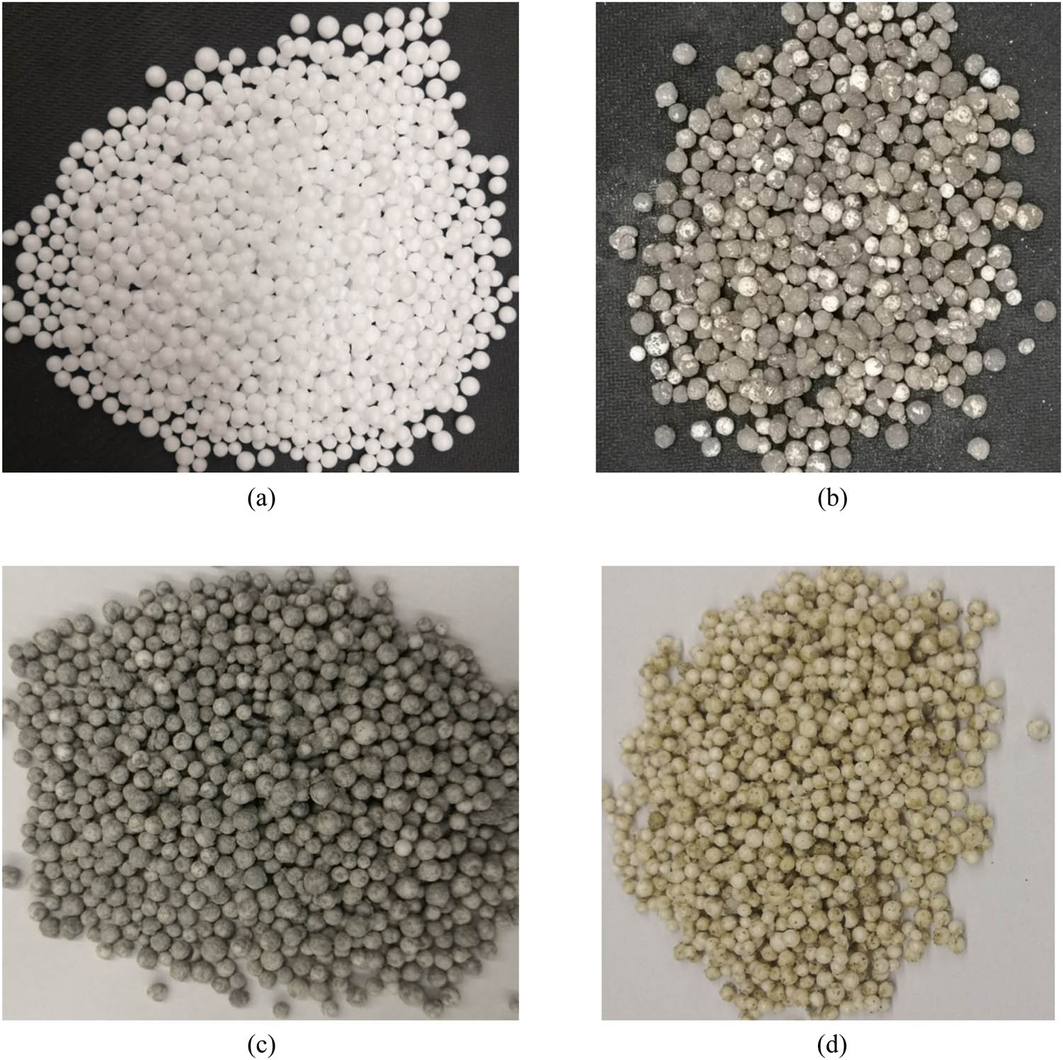
EPS particles and wrapped EPS particles: (a) EPS particles, (b) MPC-wrapped EPS particles, (c) UHPC-wrapped EPS particles, and (d) WPU-wrapped EPS particles.
2.3 Characterization of EPS-coated particles
The SL150 series optical tester of Kono Industry Co., Ltd (Shanghai City, China) is used to test the contact angle of wrapped EPS particles. The contact angle meter is mainly composed of light source control parts, charge coupled device (CCD) camera, sample console, and reagent control parts, as shown in Figure 2. By regulating the reagent control part, the droplets are suspended at the tip of the needle and slowly contacted with EPS particle or wrapped EPS particles placed horizontally on the sample table or the glass sheet. The droplets finally stay on the particle surface, as shown in Figure 3. Under the background of light emitting diode light source with appropriate brightness, CCD camera captures and clearly images the droplets falling on the surface of glass sheet, and accurately measures the contact angle between droplets and particles through analysis software.
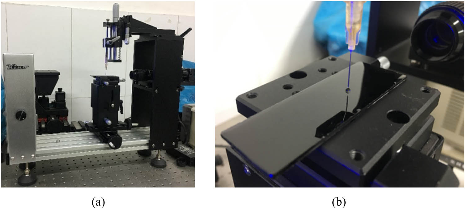
(a) Contact angle tester and (b) reagent droplets.
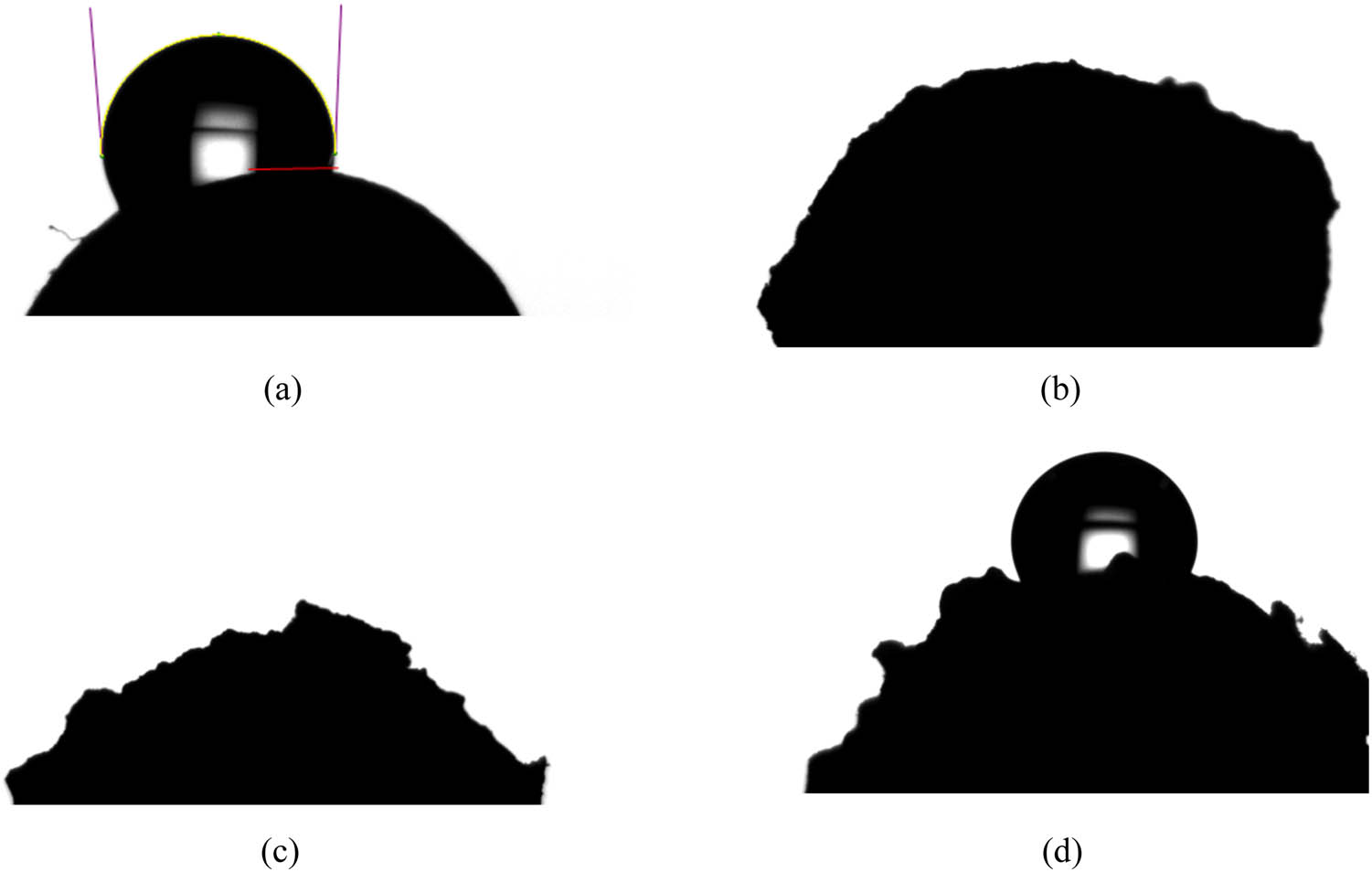
Contact angle test of EPS particle and wrapped EPS particle: (a) contact angle of EPS particle, (b) contact angle of MPC coating, (c) contact angle of UHPC coating, and (d) contact angle of WPU coating.
When water drops on the surface of EPS particles wrapped with MPC and UHPC, the water quickly covers the surface and moistens the surface, and the water drops disappear. When water drops on the surface of EPS particles wrapped with WPU coating, the water is flat; when water drops on the surface of unmodified EPS particles, only individual water drops adhere to the EPS surface and show a circular shape. The test results show that the contact angle of MPC and UHPC-wrapped EPS particles is 0°, WPU-wrapped EPS particles is 45.8°, and EPS particle is 93.6°, as shown in Figure 3. The hydrophilic property of wrapped EPS particles is significantly improved.
2.4 Test mix proportion and specimen preparation
Four groups of EPS concrete cube compressive strength specimens and prismatic flexural specimens were made. Among them, 1# EPS particles are not wrapped and used for comparison, 2# EPS particles are wrapped with MPC, 3# EPS particles are wrapped with UHPC, and 4# particles are wrapped with WPU. The total amount of cementing materials in the mix proportion of 1# test piece is 678 kg, in which the cement content is 76% of cementing materials, silica fume and microbeads are mixed according to the mass ratio of 1:2, PCE is 1.1% of the cementing materials, and the water binder ratio is controlled at 0.24. For the mix proportion of the other three kinds of concrete, the materials used to wrap EPS are subtracted from the original mix proportion; EPS concrete mix proportion is shown in Table 1. In the mixing process, first, the powder was poured into the mixer and mixed for half a minute until the powder mixed evenly, and then add most of the water and water reducing agent until the slurry was formed; the next step, EPS particles or wrapped EPS particles were placed into the mixer and mixed with the slurry; at last, the remaining water added and the fresh EPS concrete was formed. The fresh EPS concrete is used to prepare four sets of EPS concrete cubes (100 mm × 100 mm × 100 mm) test piece and four sets of flexural test pieces (100 mm × 100 mm × 400 mm), the specimens are placed in the natural curing room after forming, the formwork is removed after 2 days, and the concrete is cured in the standard curing room for 28 days.
EPS concrete specimen mix proportion
| Test piece no. | The type of EPS | Cement | Micro beads | Sand | Silica fume | Water | Water reducing agent | EPS volume content |
|---|---|---|---|---|---|---|---|---|
| (kg/m3) | (kg/m3) | (kg/m3) | (kg/m3) | (kg/m3) | (kg) | (%) | ||
| 1# | Unmodified EPS | 517 | 108 | 357 | 52 | 166 | 7.5 | 45 |
| 2# | MPC-wrapped EPS | 370 | 108 | 357 | 52 | 162 | 7.5 | 45 |
| 3# | UHPC-wrapped EPS | 476 | 96 | 316 | 47 | 151 | 7.5 | 45 |
| 4# | WPU-wrapped EPS | 517 | 108 | 282 | 52 | 166 | 7.5 | 45 |
2.5 Mechanical property test
According to the current Chinese National Standard GB/T50081-2019 [15], the cube compressive strength of four groups of specimens cured for 7, 14, and 28 days and the flexural strength of specimens cured for 28 days are tested; the test device is shown in Figure 4. Through these two experiments, the effects of EPS wrapped with three materials on the mechanical properties of EPS concrete are studied.
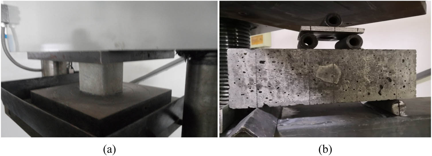
Compressive and flexural test device: (a) concrete strength test and (b) concrete flexural test.
2.6 Microperformance test
Observe the section of cube specimen through computed tomography (CT) test to obtain the EPS particles distribution. YXLON FF35 CT scanning testing machine (YXLON, Hamburg Germany) is used for CT test; the size of the sample is 100 mm × 100 mm × 100 mm; the surface morphology of EPS particles, wrapped EPS particles, and the interface transition zone (ITZ) of EPS concrete were observed by scanning electron microscope (SEM). The electron microscope use ZEISS MERLIN COMPACT field emission SEM (Carl Zeiss AG, Aalen, Germany) with an accelerating voltage of 10 kV; before observation in the electron microscope, EPS particles and wrapped EPS particle samples are sprayed with gold. EPS concrete samples used the concrete fragments located in the center of the test piece after cube compressive strength test. The section morphology of the samples is observed, and the bonding effect of EPS particle and wrapped EPS particle with cement base is studied and analyzed. CT testing machine and SEM are shown in Figure 5.
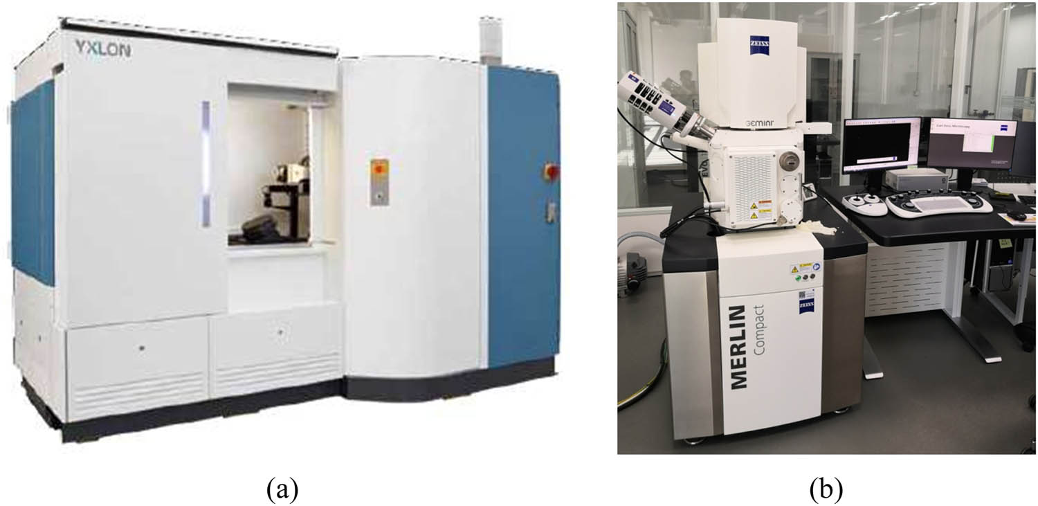
Microperformance test instrument: (a) CT testing machine and (b) SEM.
3 Test results and analysis
In this section, the homogeneity of EPS concrete is analyzed by slicing specimens and EPS area distribution uniformity index method. We tested the strength of EPS concrete and studied the ITZ of EPS concrete by SEM. The mechanical properties of EPS concrete are revealed from the microscopic point of view.
3.1 Distribution of EPS particles
As can be seen from the Figure 6(a), there is more slurry in the lower part of unmodified EPS concrete, there are many EPS particles in the upper part of the specimen. This phenomenon shows that the apparent density of EPS of 1# specimen is small, uneven floating occurred. However, EPS particles in test piece 2#, test piece 3#, and test piece 4# are evenly distributed inside. Therefore, by using wrapping technology on the surface of EPS particles, it can significantly reduce the nonuniformity of EPS particles in concrete.
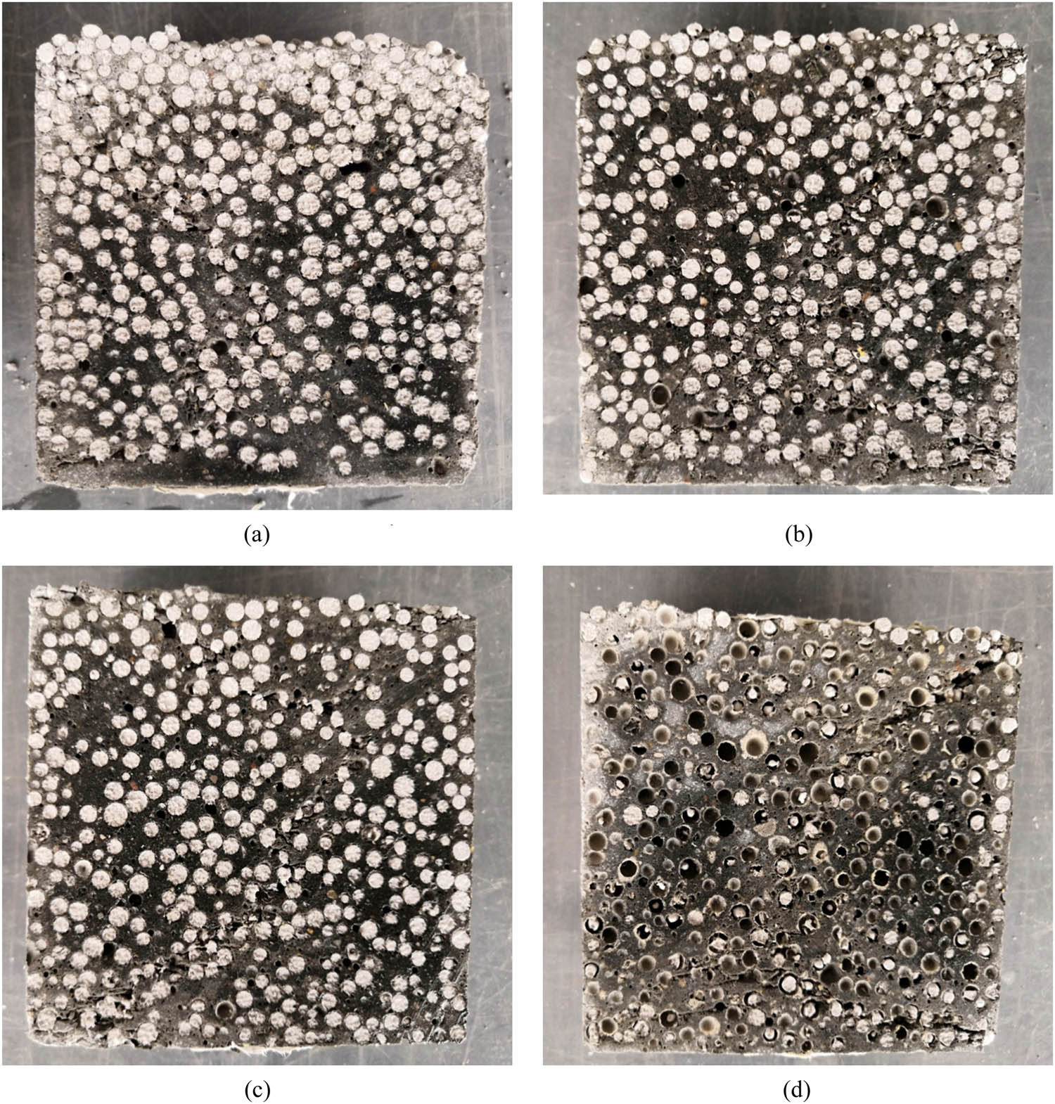
Section morphology of EPS concrete: (a) 1# test specimen, (b) 2# test specimen, (c) 3# test specimen, and (d) 4# test specimen.
Figures 7–10 show the CT scan slice of the specimen. The scanning slice map is divided into three parts: upper, middle, and lower parts with equal area, the EPS areas in the upper, middle, and lower parts are calculated by Image Pro Plus software (Media Cybernetics, Maryland USA), and the relative values of the total area of EPS in the upper, middle, and lower parts are obtained. The EPS area distribution uniformity index is calculated according to the following formula [16]:
E A is the uniformity index of EPS area distribution, A U is the relative value of EPS area in the upper region, A M is the relative value of EPS area in the central region, A D is the relative value of EPS area in the lower region, and the greater the uniformity index of EPS area distribution, the more evenly EPS is distributed in concrete. The calculation results of the test piece are shown in Table 2; the concrete prepared by EPS wrapped with WPU has the best uniformity, and the uniformity index of EPS area distribution was 0.90.
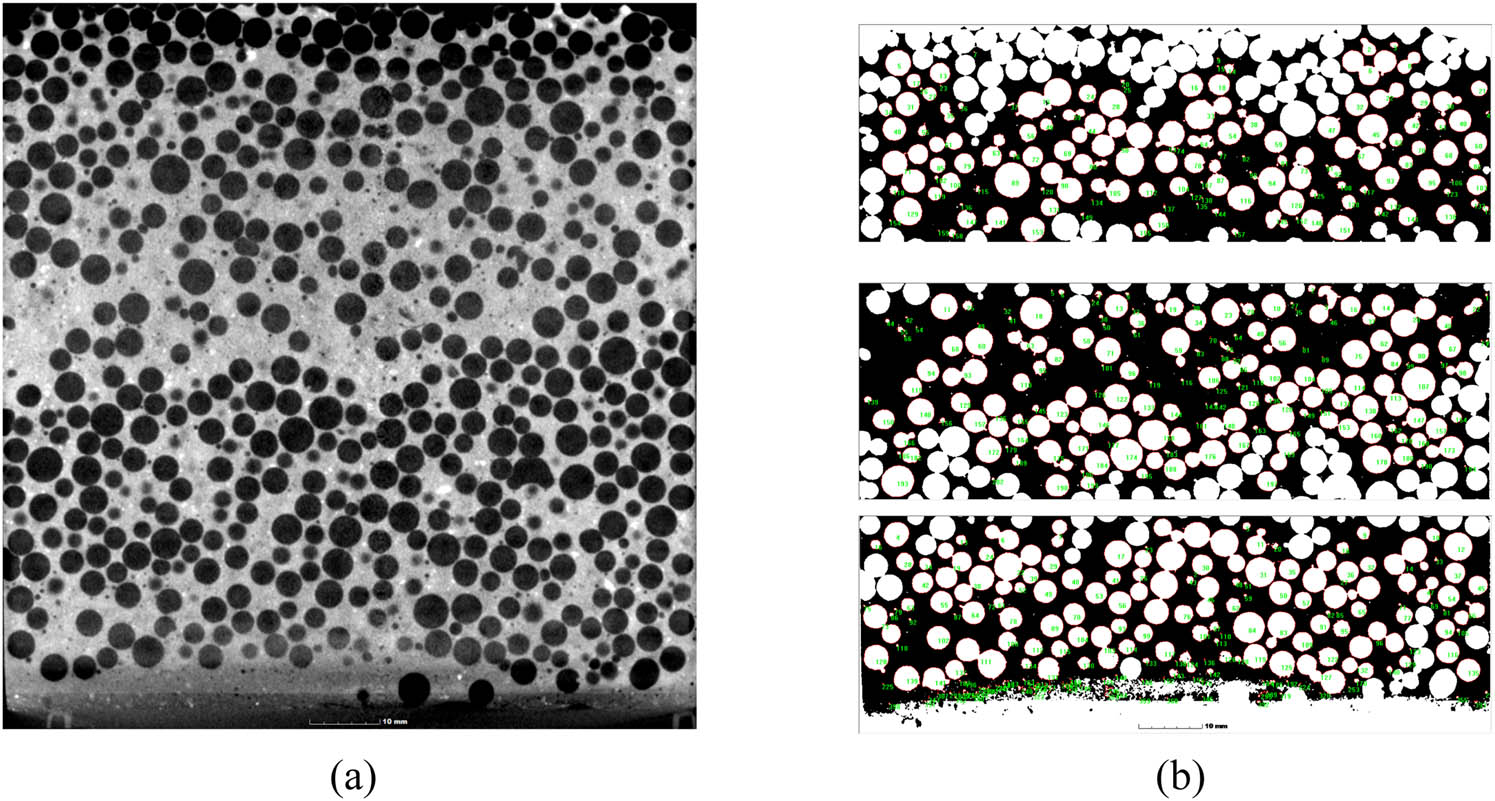
1# specimen CT scanning section and EPS area: (a) CT scan and (b) upper, middle, and lower EPS area.
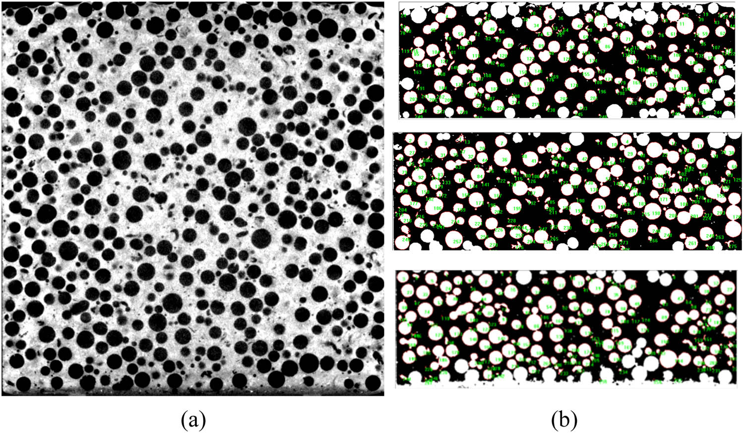
2# specimen CT scanning section and EPS area: (a) CT scan and (b) upper, middle, and lower EPS area.
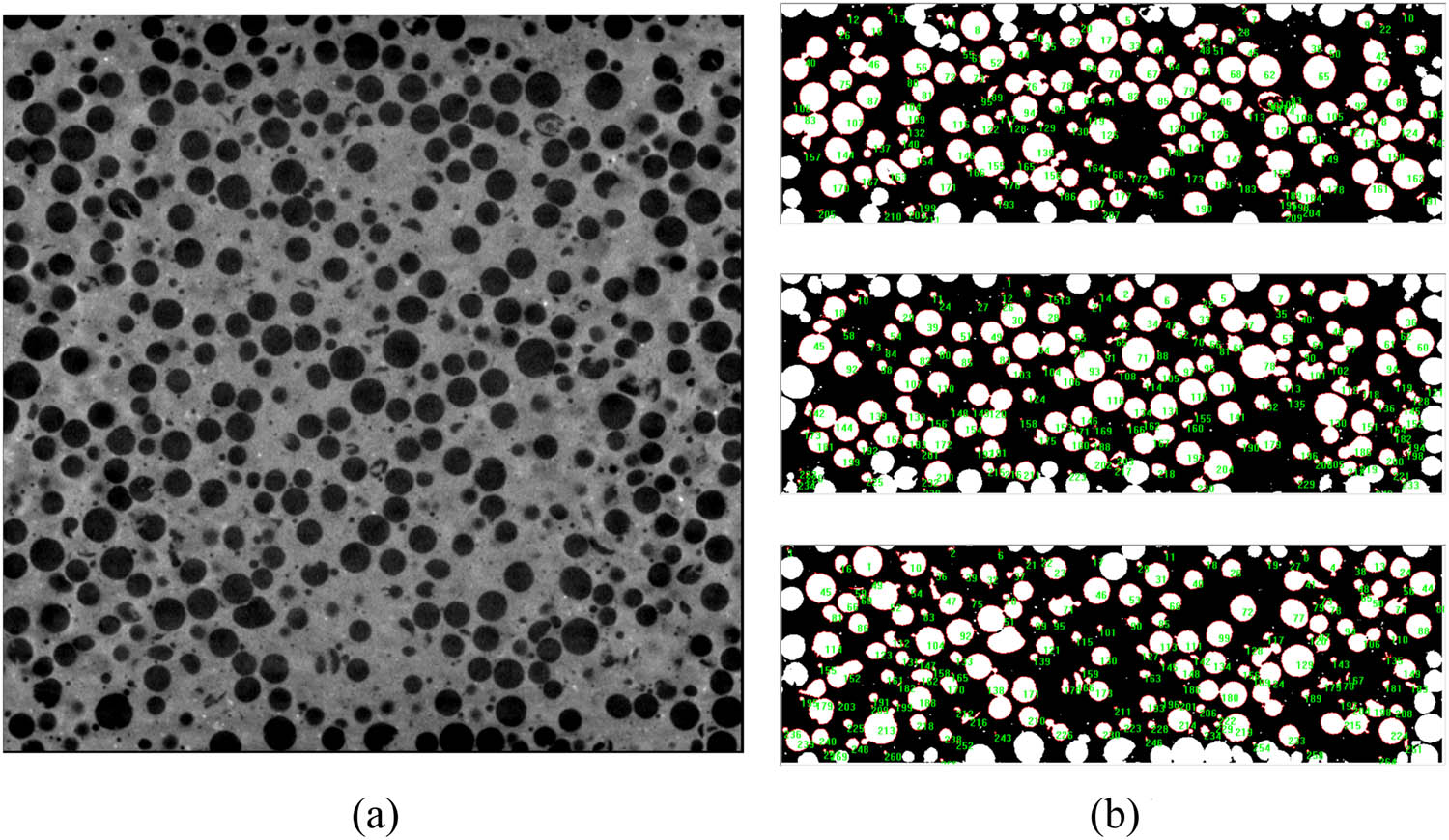
3# specimen CT scanning section and EPS area: (a) CT scan and (b) upper, middle, and lower EPS area.
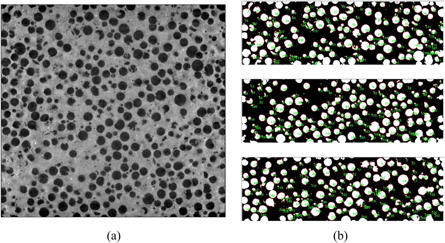
4# specimen CT scanning section and EPS area: (a) CT scan and (b) upper, middle, and lower EPS area.
EPS concrete uniformity index
| Specimen number | Area | Relative value of total area of EPS | The uniformity index of EPS |
|---|---|---|---|
| 1# | Upper | 0.86 | 0.77 |
| Middle | 1.00 | ||
| Lower | 0.91 | ||
| 2# | Upper | 0.89 | 0.82 |
| Middle | 1.00 | ||
| Lower | 0.93 | ||
| 3# | Upper | 1.08 | 0.89 |
| Middle | 1.00 | ||
| Lower | 0.97 | ||
| 4# | Upper | 0.95 | 0.90 |
| Middle | 1.00 | ||
| Lower | 0.95 |
3.2 Strength results and analysis
The cube compressive strength test results are shown in Figure 11. The cube compressive strength of 1# specimen decreases with the increase of age, the compressive strength of 2#, 3#, and 4# specimens increase gradually with the increase of age. Compared with unmodified EPS, the concrete of EPS particles wrapped with MPC, UHPC, and WPU, the compressive strength of concrete increased by 78, 88, and 113%, respectively, and the flexural strength increased by 37, 60, and 88%, respectively.
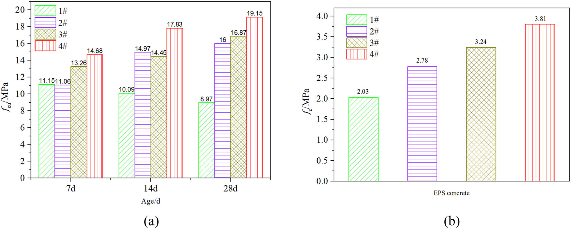
Comparison of EPS concrete strength: (a) cube strength and (b) flexural strength.
The concrete strength of EPS without wrapped decreased with the increase of age; the main reason is that EPS particles float up, EPS particles are more distributed in the upper part of the concrete, and there are relatively few cementing materials in the upper part. With the increase of curing age, EPS particles were infiltrated by water, EPS particles softened in water, the strength of EPS concrete decreases. The strength of concrete of EPS particles wrapped with other three materials increases gradually; that is, because the wrapped material forms a shell on the surface of EPS particle, under the action of external force, the force is dispersed around the shell.
According to the first strength theory, material fracture is caused by maximum tensile stress [17]. MPC have some defects, such as high brittleness, poor crack resistance, and deformation ability [18]; therefore, the shell is relatively easy to damage; WPU has strong adhesion, it is a kind of material with strong impact resistance, and the formed shell is not easy to damage; therefore, the concrete strength is relatively higher.
3.3 Microperformance test and analysis
In this section, the surface morphology and ITZ of EPS concrete are analyzed by SEM test. The mechanical properties of EPS concrete are explained from the microscopic point of view.
3.3.1 EPS particles and wrapped EPS particles
EPS particles and EPS particles wrapped with three materials were observed by SEM, as shown in Figure 13. Figure 12 shows that the surface of EPS particle is very smooth, but the surface of EPS particle wrapped by the material is rough. The wrapping material forms a shell on the surface of EPS, and it can be clearly seen that polyurethane mortar particles are adhered to the surface of WPU coating and the rough surface formed by the wrapping material is conducive to bite with the external cement base; there are a few cracks in MPC coating because MPC has poor crack resistance; the EPS particles wrapped by UHPC were relatively intact.
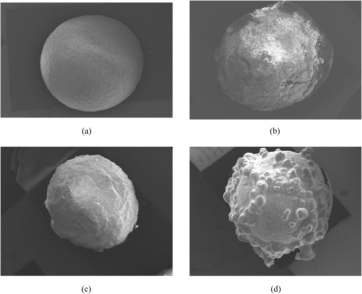
EPS particle and wrapped EPS particles: (a) EPS particle, (b) MPC-wrapped EPS particle, (c) UHPC-wrapped EPS particle, and (d) WPU-wrapped EPS particle.
1# concrete specimen SEM.
3.3.2 Analyze ITZ
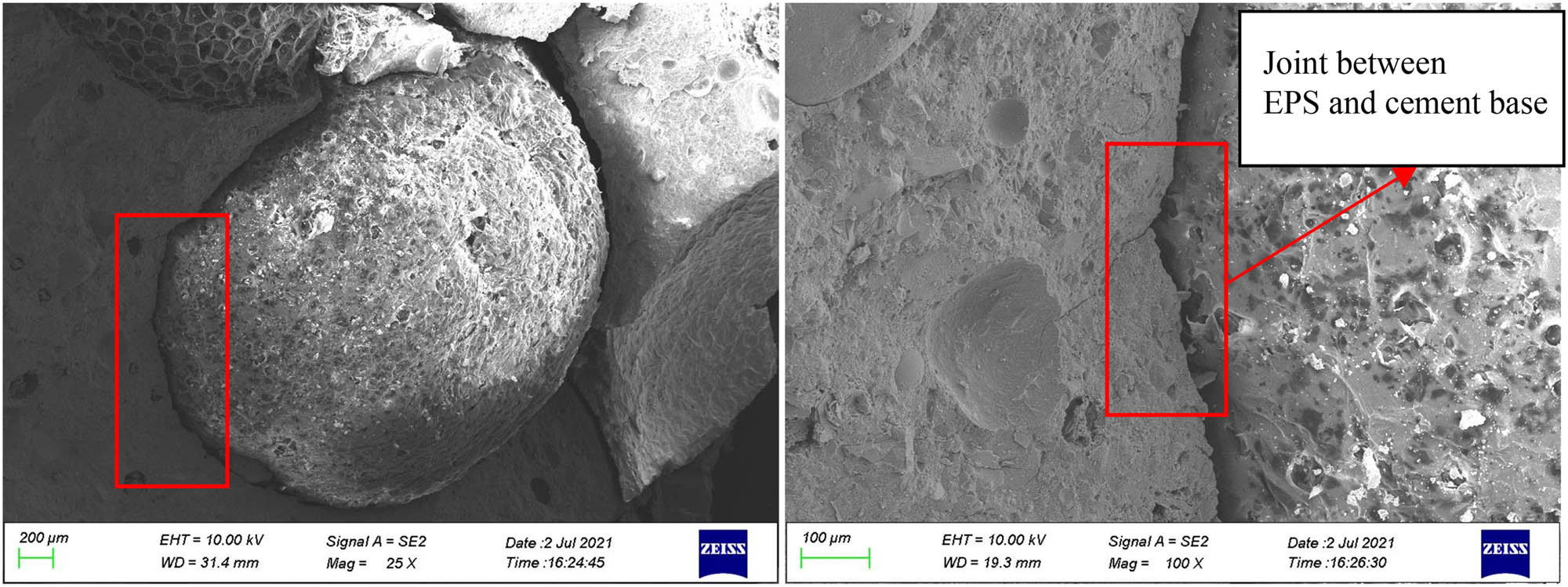
ITZ is the weakest link of concrete materials [19]; it has high porosity and low strength and easy to become the expansion area of cracks [20]. The ITZ between EPS and cement base in EPS concrete was observed by SEM, the gap in the ITZ of unmodified EPS is obvious, as shown in Figure 13. The interfacial adhesion between unmodified EPS and cement-based is weak; there are loose gaps around the interface, the gap width of the ITZ is about 20 µm, and this is due to the hydrophobic property of EPS surface and the slurry is difficult to adsorb on the particle surface.
MPC coating is in close contact with EPS particles, as shown in Figure 14. It shows that MPC coating and cement base can be well integrated with each other, and MPC wrapping layer is in close contact with cement base. The gap of ITZ is not obvious.
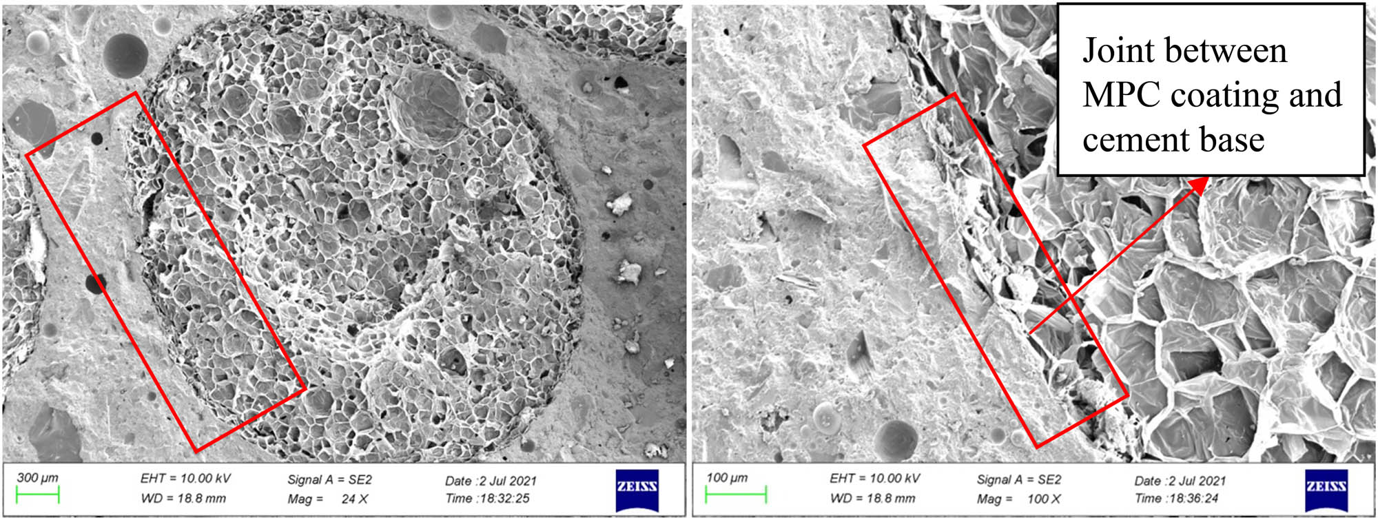
2# concrete specimen SEM.
The ITZ between UHPC coating and cement-based interface is shown in Figure 15. Observed at 200× magnification, the interface between UHPC coating and cement base is particularly tight, and the gap between the wrapper layer and the cement base is particularly small, and it is about 1 µm.
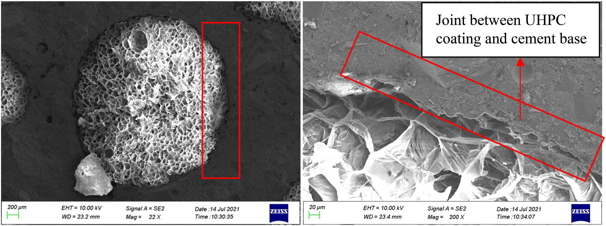
3# concrete specimen SEM.
The ITZ between WPU coating and cement base is shown in Figure 16. WPU coating is in close contact with cement base. The periphery of the ITZ is intact, and there are no microcracks and other defects. The gap width between WPU coating and cement base is below 1 µm. The modified EPS particles can effectively inhibit the weak connection between EPS particles and inorganic cementing material.
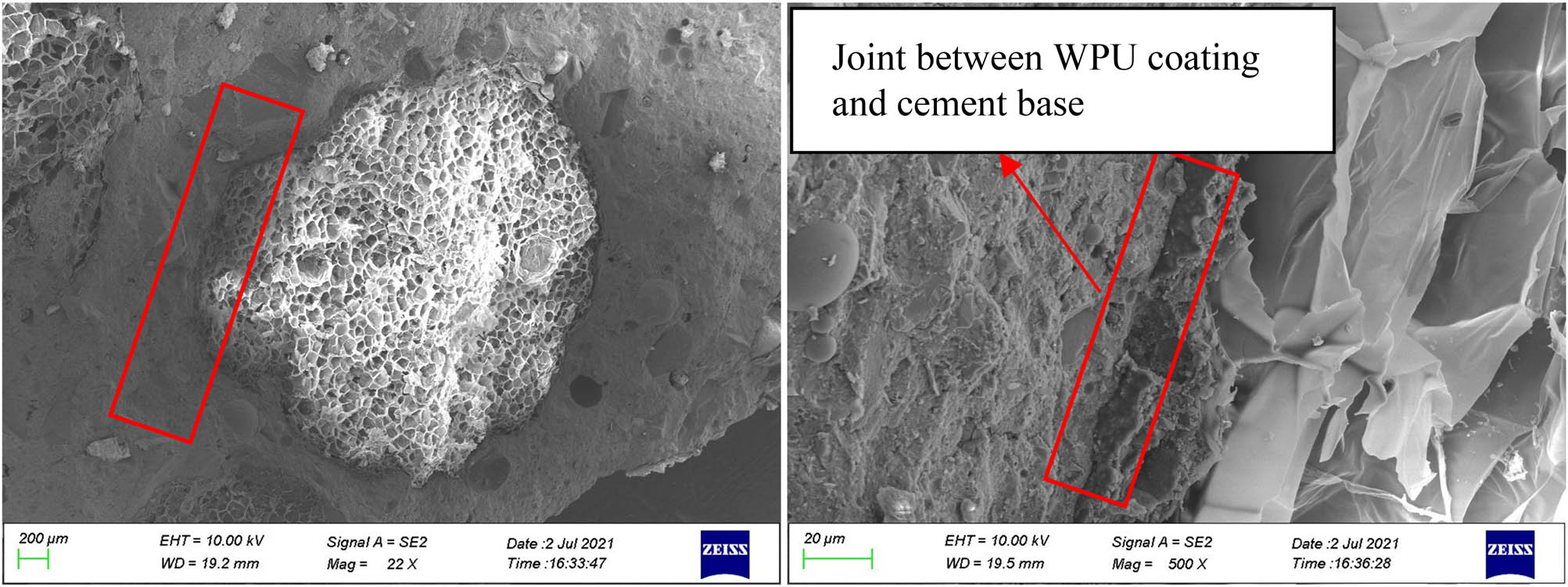
4# concrete specimen SEM.
4 Analysis of action mechanism of modified EPS concrete
4.1 Theoretical analysis
Through the test, it is found that the concrete strength of EPS particles wrapped is improved obviously. EPS concrete is a kind of composite material; it can be explained by Voigt model [21]. The calculation diagram of the Voigt model is shown in Figure 17(a) [22]. In this model, the elastic modulus of the composite material can be calculated according to formula (2). In formula (2), C r represents the volume fraction of each phase material, and E r represents the elastic modulus of each phase material.
We regard the concrete prepared by wrapped EPS particles as a four-phase model. The computation model is shown in Figure 17(b), which is composed of EPS, wrapping material, mortar, and the ITZ. Zone I represents EPS, Zone II represents the wrapper layer, areas [a, b] are the wrapping layer, Zone III represents ITZ, and Zone IV represents mortar area. When calculating the elastic modulus, we ignore the influence of ITZ because the thickness of ITZ is very small, and it can be almost ignored compared with other part. When calculating the elastic modulus of concrete with EPS wrapped, we define the volume fraction of mortar layer is C 0, the elastic modulus of mortar is E 0; the volume fraction of wrapper layer is C 1, the elastic modulus of the wrapping material is E 1; the volume of EPS particles is C 2, the elastic modulus is E 2; the elastic modulus of the whole model can be expressed by E m1, it can be calculated according to formula (3). Compared with the concrete of EPS particles wrapped, the concrete prepared by EPS particles not wrapped have no wrapping layer, and it is equivalent to that the wrapping layer is replaced by mortar layer. Therefore, the volume fraction of mortar layer is (C 0 + C 1), and the elastic modulus of mortar and the parameters of EPS are the same as the concrete of EPS particles wrapped; the elastic modulus of the whole model can be expressed by E m2, and it can be calculated according to formula (4). Because the wrapper layer is made of high strength materials, E 1 is greater than E 0. By comparing formulas (3) and (4), it can be found that E m1 is greater than E m2; therefore, the concrete strength of EPS after wrapping is higher.
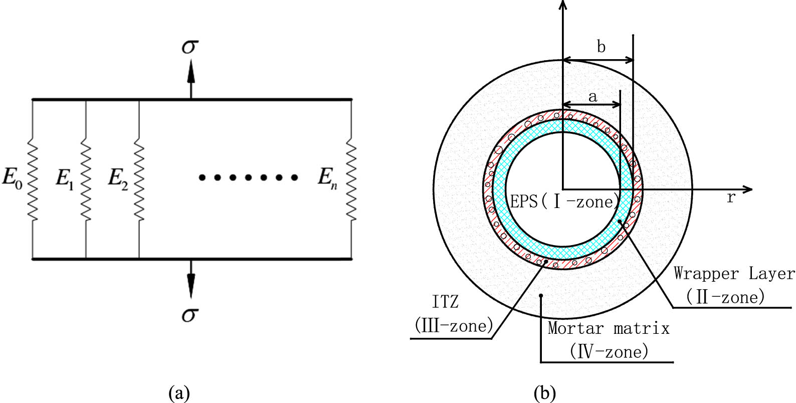
EPS concrete model: (a) Voigt model and (b) computational model.
4.2 Other analysis
The performance improvement of concrete of EPS particles wrapped can also be explained from other aspects. The damage of concrete is greatly affected by holes [23], and EPS particle in EPS concrete is equivalent to a hole. The concrete prepared by wrapped EPS is equivalent to making a shell outside the hole, and the wrapper layer is equivalent to a shell. The strength of the shell is relatively high and can form “Arch effect,” and when a part of the outer shell is subjected to pressure, it will be evenly transmitted to the rest of the surrounding parts and reduce the effect and significantly improve the bearing capacity. However, unmodified EPS particles have very low strength and do not have this effect. Besides, the surface hydrophilic property of EPS was improved after wrapped; the surface becomes rougher, wrapping materials can have a very strong bond with cement-based materials, the gap in the ITZ becomes smaller; the hydration reaction on the surface of wrapped EPS particles is more sufficient. Moreover, after EPS is wrapped, the weight of EPS particles is increased, and the density difference between EPS particles and cement paste is reduced, it is beneficial to improve the uniformity of particles in concrete.
5 Conclusion
In this study, the wrapping technology of EPS particles is put forward. EPS particles were successfully wrapped with MPC, UHPC, and WPU. Concrete was prepared by wrapped EPS particles, and the mechanical properties and micro properties of concrete were tested. Through the test of specimen section and CT scanning, it was found that the wrapped EPS particles have a very high uniformity in concrete; the concrete prepared by wrapping EPS with WPU is the most uniform. When comparison with unmodified EPS, the compressive strength of concrete of EPS wrapped with MPC, UHPC, and WPU increased by 78, 88, and 113%, respectively, and the flexural strength increased by 37, 60, and 88%, respectively. SEM test results found that the wrapped particles are in close contact with the cement base, and the gap width in the ITZ is much smaller than that of the unwrapped EPS particles. Finally, the reinforcement mechanism of wrapped EPS particles is reasonably explained by Voigt model and other views; it is mainly attributed to the improvement of surface hydrophilic property, the increase of surface roughness, and the sufficient hydration reaction of the surface.
-
Funding information: This research was financially supported by the Beijing Major Science and Technology Projects (No. Z191100008019002), Science and Technology Project Plan of the Ministry of Housing and Urban-Rural Development of the people’s Republic of China “Study on fabricated light steel light concrete structure system” (2016-K5-001).
-
Conflict of interest: Authors state no conflict of interest.
References
[1] Wang X, Ren H, Cai W et al. Index decomposition analysis of building energy consumption in chongqing: 2000–2014. Proceedings of the 21st International Symposium on Advancement of Construction Management and Real Estate. Hong Kong, China; 2016.10.1007/978-981-10-6190-5_82Search in Google Scholar
[2] Zheng Z, Zhong J, Xie B. Summary of the development of energy-saving technologies in fabricated building systems. J Building Energy Efficiency. 2020;48:48350-138.Search in Google Scholar
[3] Cui CC. Seismic Behavior of Light Gauge Steel Reinforced EPS Concrete Shear Walls [Chinese Dissertation]. Beijing: Tsinghua University; 2016.Search in Google Scholar
[4] Liu YC. Study on experiment and constitutive model of EPS concrete and energy-saving evaluation. Institute of Engineering Mechanics [Chinese Dissertation]. Harbin: Institute of Engineering Mechanics, China Earthquake Administration; 2013.Search in Google Scholar
[5] JGJ383-2016. Technical specification of lightweight steel and lightweight concrete structures. Beijing. China: Ministry of Construction of the People’s Republic of China; 2016 (in Chinese).Search in Google Scholar
[6] Pan W, Deng D, Yuan T. ESP light concrete matching ratio affecting on the fluidity and its strong mechanism. Concrete. 2006;196(2):63–9.Search in Google Scholar
[7] Chen B, Chen L. Study on mechanical properties of EPS lightweight concrete. China Concrete and Cement Products. 2004;173(3):41–5.Search in Google Scholar
[8] Ran XM. Experimental study on the influence of silica fume to static and dynamic mechanical properties of EPS concrete [Chinese Dissertation]. Hefei: Anhui University of Science and Technology; 2016.Search in Google Scholar
[9] Dong J, Cao J, Li Y. Interfacial modification of EPS cement based composite materials. J Building Mater. 2019;22(6):917–21.Search in Google Scholar
[10] Hu X. Research on the processing technology of expanded polystyrene (EPS) particles surface modification and the properties of thermal insulation mortar [Chinese Dissertation]. Nanchang: Nanchang University; 2008.Search in Google Scholar
[11] Hu X, Huang S, Zhang S. EPS surface modification and its effect on mechanical properties of thermal insulation mortar. New Building Materials. 2008;11:42–4.Search in Google Scholar
[12] Chen X, Dong JW. Relationship between EPS modification method and mechanical properties of cement-based materials. Concrete. 2013;284(6):13–4.Search in Google Scholar
[13] Chen B, Liu J. Properties of lightweight expanded polystyrene concrete reinforced with steel fiber. Cem Concr Res. 2004;34(7):1259–63.10.1016/j.cemconres.2003.12.014Search in Google Scholar
[14] Chen B, Liu J. Mechanical properties of polymer-modified concretes containing expanded polystyrene beads. Constr Build Mater. 2007;21(1):7–11.10.1016/j.conbuildmat.2005.08.001Search in Google Scholar
[15] GB/T 50081-2019. Standard for test methods of concrete physical and mechanical properties. Beijing, China: Ministry of Construction of the People’s Republic of China; 2019 (in Chinese).Search in Google Scholar
[16] Song SB. Effect of EPS volume fraction on physical and mechanical properties of EPS concrete [Chinese Dissertation]. Shenzhen: Shenzhen University; 2017.Search in Google Scholar
[17] Guo ZH. Deformation and strength of concrete-experimental foundation and constitutive relation. Beijing: Tsinghua University Press; 1997.Search in Google Scholar
[18] Qin JH. Study on Preparation and Mechanical Behavior of Ultra-high Strength Magnesium Phosphate Cement Composites [Chinese Dissertation]. Chongqing: Chongqing University; 2019.Search in Google Scholar
[19] Wong HS, Buenfeld NR. Euclidean distance mapping for computing microstructural gradients at interfaces in composite materials. Cem Concr Res. 2006;36(6):1091–7.10.1016/j.cemconres.2005.10.003Search in Google Scholar
[20] Wang Z, Zhang Y, Shen L. Coupled model of fracture seepage and dissolution in concrete interface transition zone considering the influence of microstructure. Eng Mechanics. 2021;38(6):133–42.Search in Google Scholar
[21] Voigt W. Ueber die Beziehung Zwischen den beiden Elastizitätsconstanten isotroper Körper. Annalen der Physik. 1889;274(12):573–8.10.1002/andp.18892741206Search in Google Scholar
[22] Jin L. Study on meso-scopic model and analysis method of concrete [Chinese Dissertation]. Beijing: Beijing University of Technology; 2014.Search in Google Scholar
[23] Lei G, Han J, Dang F. Comparative analysis of microscopic concrete numerical model. Chinses J Appl Mechanics. 2017;34(2):322.Search in Google Scholar
© 2022 Yuan Ji et al., published by De Gruyter
This work is licensed under the Creative Commons Attribution 4.0 International License.
Articles in the same Issue
- Regular Articles
- Experimental investigations of a novel pressure microfoam preparation device for dust removal
- Influence of hydrothermal aging on the mechanical performance of foam core sandwich panels subjected to low-velocity impact
- Experimental study on surface wrapping strengthening of EPS particles and its concrete performance
- Modification of mechanical properties of Shanghai clayey soil with expanded polystyrene
- A new EPS beads strengthening technology and its influences on axial compressive properties of concrete
- A novel superabsorbent material based on soybean straw: Synthesis and characterization
- Use of line laser scanning thermography for the defect detection and evaluation of composite material
- Research on back analysis of meso-parameters of hydraulic cemented sand and gravel based on Box-Behnken design response surface
- Hot deformation behavior and microstructure of a 0.5 wt% graphene nanoplatelet reinforced aluminum composite
- Analysis of electromagnetic characteristics of the proposed composite four-rail electromagnetic launcher
- Preparation and characterization of a graphene hybridizing polyurethane damping composite
- Effects of layup parameters and interference value on the performance of CFRP–metal interference fit joints
- Vibration and noise reduction of pipelines using shape memory alloy
- Finite element analysis of behavior and ultimate strength of composite column
- Dynamic response of functionally graded plate under harmonic load with variable gradient parameters
- Deformation behavior of rubber composite based on FEA and experimental verification
- Effects of Z-pin on moisture absorption property and damage mode under flexural load for carbon fiber composite
- Design and testing of a smart rubber stave for marine water-lubricated bearings
- Study of carbon nano-modifier of fly ash in cement concrete mixtures of civil engineering
- Analysis of multiple impact tests’ damage to three-dimensional four-directional braided composites
- Theoretical analysis of aluminum honeycomb sandwich panel supported by reinforced concrete wall under low-speed impact load
- Effects of local fiber discontinuity on the fatigue strength parameter at the fiber inclusion corner in fiber-reinforced composites
- Experimental investigation on compressive properties of three-dimensional five-directional braided composites in hygrothermal environment
- Failure process of steel–polypropylene hybrid fiber-reinforced concrete based on numerical simulations
- A simple method for measuring the monofilament diameter of continuous filament yarn with high bending stiffness via synthetic laser imaging
- Span length effect on flexural properties of composite laminate reinforced with a plain weave carbon fiber fabric in a polymer matrix
- Mechanical properties improving and microstructure characterization of inorganic artificial stone binder
- Effect of thermal treatment process on the structure of C/SiO2 composite aerogels
- Mechanical and corrosion resistance analysis of laser cladding layer
- Wear and corrosion mechanisms of Ni–WC coatings modified with different Y2O3 by laser cladding on AISI 4145H steel
- Damage and failure analysis of composite stiffened panels under low-velocity impact and compression after impact with damp-heat aging
- In-situ CT characterization of 2D woven SiCf/SiC composite loading under compression
- Effect of the manufacturing process on the equivalency qualification of glass fiber reinforced polymer
- Study of concrete properties based on crushed stone sand mixture and fiber of fly ash of thermal power plants
- Establishment of wear mechanism distribution diagram of ZTAp-reinforced iron matrix composites
- Calculation method of elastic modulus for carbon fiber-reinforced plastics considering inhomogeneous interphase
- An experimental study on the failure and enhancement mechanism of bolt-strengthening GFRP T-joint subjected to tensile loading
- The viability of cell that encapsulated in calcium alginate hydrogel beads
- Discussion of ceramic bar reinforced TWIP steel composite structure
- A theoretical framework underlying an accelerated testing method and its application to composites under constant strain rates and fatigue loading
- Theoretical analysis of interfacial design and thermal conductivity in graphite flakes/Al composites with various interfacial coatings
- Multiscale heat conduction and fractal oxidation behaviors of needle-punched carbon/carbon composites
- Numerical simulation of composite grid sandwich structure under low-velocity impact
- Wear properties of Al/TiO2 composites fabricated via combined compo-casting and APB process
- Review Articles
- Application of melanin as biological functional material in composite film field
- Review on research progress of cemented sand and gravel dam
- Communication
- Fabrications and microstructure analysis of cobalt-based coatings by an easy-coating and sintering process
- Letter to the Editor
- Investigation on mechanical and conductive behaviors of nano-graphite-based concrete