A large-scale single-mode array laser based on a topological edge mode
-
Natsuko Ishida

 ,
Yasutomo Ota
,
Wenbo Lin
,
Yasutomo Ota
,
Wenbo Lin

Abstract
Topological lasers have been intensively investigated as a strong candidate for robust single-mode lasers. A typical topological laser employs a single-mode topological edge state, which appears deterministically in a designed topological bandgap and exhibits robustness to disorder. These properties seem to be highly attractive in pursuit of high-power lasers capable of single mode operation. In this paper, we theoretically analyze a large-scale single-mode laser based on a topological edge state. We consider a sizable array laser consisting of a few hundreds of site resonators, which support a single topological edge mode broadly distributed among the resonators. We build a basic model describing the laser using the tight binding approximation and evaluate the stability of single mode lasing based on the threshold gain difference Δα between the first-lasing edge mode and the second-lasing competing bulk mode. Our calculations demonstrate that stronger couplings between the cavities and lower losses are advantageous for achieving stable operation of the device. When assuming an average coupling of 100 cm−1 between site resonators and other realistic parameters, the threshold gain difference Δα can reach about 2 cm−1, which would be sufficient for stable single mode lasing using a conventional semiconductor laser architecture. We also consider the effects of possible disorders and long-range interactions to assess the robustness of the laser under non-ideal situations. These results lay the groundwork for developing single-mode high-power topological lasers.
1 Introduction
High power semiconductor lasers have been of great interest to the industrial market for their wide applications, prompting enormous efforts in improving their performance. A straightforward approach for increasing laser output power is to widen the emitting area, as adopted in tapered [1], broad-area [2] and array lasers [3]. However, wider emitting areas in general result in multi-mode lasing and thereby in the degradation of laser beam quality. To overcome this issue, various techniques have been examined to minimize the effects of unwanted lateral guided modes over the last few decades [4–8]. Singlemodeness can often be improved by a delicate cavity design that cleverly takes advantages of the difference between the spatial mode profiles of the target and other undesired modes [9–19]. A remarkable example reported recently is based on a two-dimensional photonic crystal band-edge resonator with 10W-class output from a single optical mode [20]. However, the designs of these structures tend to be highly delicate and sometimes significantly complicate the fabrication process of the device. Such complexity in design may motivate to find a simpler scheme that enables high power single mode semiconductor lasers.
A potential approach in this direction is that of topological lasers, which leverage topological photonics for designing lasing optical modes [21–35]. Topological photonics offers a novel route for designing optical modes with distinctive properties compared to conventional approaches [36–41]. A typical topological laser consists of a single topological edge mode that deterministically appears in a topological bandgap as a result of a topological mechanism called the bulk-edge correspondence [42–44]. The topological edge modes are known to behave robustly against certain perturbations due to topological protection, which is suitable for developing robust single mode lasers. Topological ring lasers have been demonstrated using one-dimensional topological edge states propagating at the exterior of the bulk emulating quantum Hall [21], quantum spin Hall [23, 34] and quantum valley Hall systems [31, 35]. Single mode lasing devices have been demonstrated in these systems and the possibility of realizing robust single mode lasers with high slope efficiencies has been discussed. More recently, an electrically pumped topological laser has also been reported at mid-infrared wavelengths [31]. Surface-emitting lasers utilizing Dirac cones or those with mass vortices also have been discussed as another candidate for a large-area laser [45, 46].
Topological lasers based on zero-dimensional edge states are another topic that has gathered interest recently. Localized topological modes in arrays of resonators, such as micropillars [22] and microring cavities [25, 26], have been combined with semiconductor gain to demonstrate lasing. Topological nanolasers have also been studied using topological photonic crystals supporting zero-dimensional interface states [28, 29] and corner states as higher-order topological states as well [47, 48]. So far, most of the works employing zero dimensional topological states aimed to investigate the lasing properties of tightly localized topological edge modes or to explore the physics of non-Hermitian topology therein [25, 26, 49], [50], [51], [52], [53]. As such, there have been limited discussions for the application of topological edge modes for high power lasers by significantly expanding the mode profile in space.
In this paper, we theoretically investigate a large-scale single-mode topological laser. We consider a sizable array laser that supports a single zero-dimensional topological edge state distributed over a few hundreds of site resonators. We formulate this model based on the tight binding approximation. Akin to a conventional analysis of semiconductor lasers [20, 54, 55], we analyze the stability of single mode operation by evaluating the threshold gain difference between the first topological mode lasing and the second bulk mode lasing. We find that the stability of the single mode lasing increases with a stronger coupling of the site resonators and reducing optical loss in them. Furthermore, we study the robustness of the single mode lasing under the presence of imperfections. From the discussion, we deduce a possible direction of the device design for robust single mode lasing with high output power. We believe our results pave a new path toward single mode high power lasers based on topological photonics.
2 Characteristics of an ideal topological edge-mode laser
2.1 Theoretical model
We discuss a large-scale topological array laser composed of a number of site resonators. Figure 1(a) shows a schematic implementation of such a laser based on Fabry–Pérot cavities, which can in principle be substituted by any other laser resonators. Each cavity supports a well-defined single lateral mode and optically couples to neighboring cavities. Well-designed couplings between the cavities allow for the appearance of a topological lateral mode distributed over the nearly all of the cavity array, as we will describe shortly later. Electrodes are patterned on specific site cavities to selectively supply gain, which promotes lasing from the designed topological mode. We target a system including a few hundred resonators. If each resonator delivers ∼100 mW output, the topological laser could be operated as a 10W-class laser.
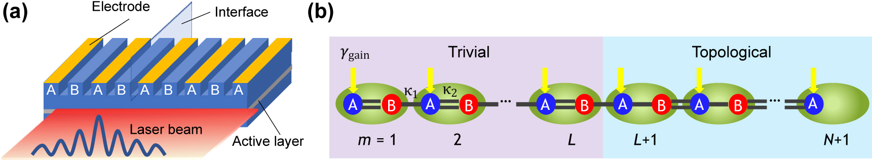
Investigated topological edge-mode array laser.
(a) Schematic of the investigated topological laser structure. (b) Tight-binding model of the laser structure. An edge mode deterministically emerges at the interface of the two topologically distinct photonic lattices. N and L correspond to the total number of dimers and the number specifying the topological phase boundary, respectively. Note that there exists a single auxiliary site at the end of the topological chain. κ 1 (single line) and κ 2 (double lines) indicate weak and strong coupling strengths between neighboring sites, respectively. γ gain expresses gain supplied on A-site. The application of this tight binding model to the system described in (a) would be valid as long as the longitudinal cavity modes behave independently or when assuming arrays of cavities supporting only single longitudinal mode such as λ/4-shifted distributed feedback resonators.
For theoretical analysis, we map this array laser to a simple tight binding model. We consider an array of single-mode resonators that resembles the Su–Schriffer–Heeger (SSH) model [56]. In the SSH model, the resonator chain is dimerized and its unit cell contains two resonators called A- and B-sites. When the coupling strengths for both the inter- and intra-unit cell hopping are the same, the model exhibits gapless energy bands in momentum space. Meanwhile, when the two coupling strengths are unequal, a gap appears between the two bands. For an SSH chain with a larger inter-cell coupling than the intra-cell coupling, its band topology becomes topologically non-trivial and topological localized modes emerge at the edges of the bulk chain according to the bulk-edge correspondence. More quantitatively, the topological properties of the energy bands can be characterized using Zak phases, which are defined by the integral of the Berry connection over the first Brillouin zone [57]. For a topological band, its Zak phase takes a nonzero value and becomes π when inversion symmetry is preserved in the system.
To obtain the desired laser cavity mode, we interface two SSH chains at the center of the system, as schematically illustrated in Figure1(b). The two chains are topologically trivial and non-trivial, respectively. In this case, a single topological interface mode appears deterministically around the interface [28, 58], with which we design a single mode laser. Since the other end of the topological SSH chain could support another edge state, we terminate the chain with an auxiliary site resonator strongly coupled to the bulk chain, by which we can suppress the emergence of the unwanted extra edge state. Note that this configuration is similar to the design reported in Reference [26]. However, they studied a tightly localized edge mode at the interface in a small lattice, in stark contrast with the current work investigating a broadly distributed interface mode in a large-scale lattice. It is also interesting to note that the topological cavity structure illustrated in Figure 1(a) is reminiscent to that of distributed feedback lasers. Indeed, the laser mode in a lambda/4-shifted distributed feedback laser can be interpreted as a special case of a topological interface mode. Nevertheless, the discrete topological lattice model preserving chiral symmetry discussed in this paper will lead to a unique field distribution capable of robust single mode lasing, making a stark contrast with conventional distributed feedback lasers, as we will demonstrate later.
The system under consideration is described by the following Hamiltonian,
where ω A,m and ω B,m are the resonant frequencies of site A and B in a dimer m, respectively, while γ A,m and γ B,m denote gain and loss. Site-to-site coupling strengths are described by κ 1,m and κ 2,m . We suppose κ 1,m < κ 2,m , such that the topological SSH chain always remains topological. The total number of the dimers and the number specifying the topological phase boundary are set as N = 100 and L = 50, respectively. Thus, the number of sites in the trivial array becomes n tri = 2L = 100, while that in the topological array does n topo = 2(N − L) + 1 = 101. The latter number includes the single auxiliary site at the end of the topological chain. We neglect the presence of unwanted longitudinal modes in each resonator to simplify the analysis. This model is valid as long as the longitudinal modes behave independently or when assuming arrays of single longitudinal mode cavities such as λ/4-shifted distributed feedback resonators. Note that, in this section, we consider an ideal case where we henceforth set (κ 1,m , κ 2,m , γ A,m , γ B,m ) = (κ 1, κ 2, γ A , γ B ) and ω A,m = ω B,m = ω for any dimer m, unless otherwise indicated.
2.2 Eigenmodes in the absence of gain and loss
To understand the basic properties of the investigated system formulated in Eq. (1), we first analyze it in the absence of gain and loss. We set the coupling parameters to (κ
1,m
, κ
2,m
) = (1.0, 1.04), which serves as a basic parameter set for the subsequent discussion. We diagonalize the Hamiltonian and analyze the energy spectrum and the spatial profiles of the eigenmodes of the system. Figure 2(a) shows computed eigenenergies ɛ plotted in the complex energy plane. In the real energy spectrum, Re(ɛ), one can see an energy gap of approximately 2|κ
1 − κ
2|, in which an in-gap mode exists as expected from the topological design discussed above. The topological mode is fixed to the zero energy and the entire energy spectrum is symmetric with respect to the zero energy according to chiral symmetry existing in the system. Note that the chiral symmetry is preserved when Hamiltonian H satisfies Γ†
HΓ = −H with an operator Γ2 = 1, where Γ is Hermitian and unitary. In general, a lattice with chiral symmetry will be bipartite and has two sublattices such that no direct transition occurs between the same sublattice sites. We inspect the spatial profile of the zero energy topological mode and plot this in Figure 2(b). The mode profile distributes over the entire lattice with amplitudes only on A-sites [25, 26]. The spatial profile is well described by an approximated analytical expression given as
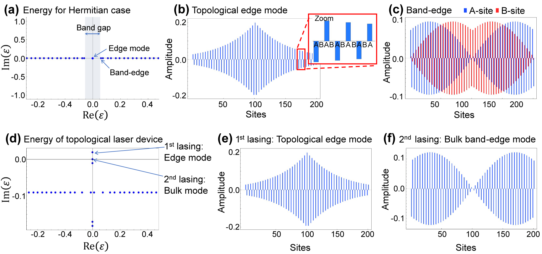
Eigenstates of the edge mode and band-edge bulk mode.
(a) The eigenenergies ɛ in the complex energy plane for the Hermitian case, zoomed around origin. (b) Spatial profile of the topological edge mode. The inset shows that the edge mode has non-zero amplitudes only on A-sites. (c) Spatial profile of the band-edge bulk mode for comparison. For (a)–(c), the parameters used are κ 2/κ 1 = 1.04, γ loss = γ gain = 0, n tri = 100 and n topo = 101. (d) The eigenenergies ɛ in the complex energy plane for the topological laser system with gain and loss, zoomed around origin. (e) Spatial profile of the first lasing mode, i.e., topological edge mode. (f) Spatial profile of the second lasing mode stemming from an amplified bulk mode, exhibiting non-zero amplitudes only on A-sites. For (d)–(f), the parameters used are κ 1 = 1.0, κ 2 = 1.04, γ loss = 0.2, and γ gain = 0.219. The system size is n tri = 100 and n topo = 101. In ((b), (c), (e) and (f)), blue and red bars indicate the amplitudes on A-site and B-site, respectively.
2.3 Eigenmodes under the presence of gain and loss
Next, we investigate the properties of the system when introducing gain and loss to assess the capability of single mode lasing. To account for modal loss normally existing in photonic devices, we assume that all site resonators experience an uniform loss at a rate γ loss. Then, we supply gain on the A-sites at a rate of γ gain. Thus, we introduce γ A = γ gain − γ loss and γ B = −γ loss as imaginary onsite potentials across all the sites. Figure 2(d) shows representative eigenenergies in the complex energy plane with γ loss = 0.2 and γ gain = 0.218. Most eigenstates show negative Im(ɛ) and are expected to behave as lossy states. In contrast, the topological edge state solely acquires an explicit positive Im(ɛ), indicating that the state becomes the first lasing mode in the system. This result confirms that our design can promote single mode lasing from the designed topological edge state broadly distributed in the lattice. Meanwhile, in the plot, there is a bulk state with nearly zero real and imaginary energies, which, with additional gain, could be positive in the imaginary part and hence a second lasing state. The presence of such a bulk mode capable of lasing leads to the unwanted competition of lasing modes in the system. To stabilize the single mode lasing from the topological edge state, it is vital to design a system that suppresses lasing from the bulk modes.
The reason why the topological edge and bulk states under concern preferentially acquire non-negative Im(ɛ) can be understood from their mode profiles presented in Figure 2(e) and (f). Both of their mode profiles have dominant amplitudes on A-sites, where gain is selectively supplied. We identified that the bulk mode with spatial profile only on the A-sites arises from a phase transition similar to that occurring in parity-time (PT) symmetric systems [59–61]. Note that, while the gain and loss are totally balanced in PT symmetric systems, we consider a system with varied gain and fixed loss. Subjected to a large supplied gain, some bulk modes experience a phase transition and choose to split in its imaginary energies (while in turn degenerate in real energies), which accompanies a drastic change of the field profiles. To gain more insight into the phase transition, we consider an infinite bulk SSH chain without any interface. In this case, the Hamiltonian represented in momentum space takes the form
where a is the lattice constant and k is a wave number. For band edge modes supported at the Brillouin zone edge, the eigenvalues are given by
Across
2.4 Threshold gain difference
A way to assess the capability of single mode lasing is to measure the threshold gain difference among the lasing modes. In this work, the threshold gain for a mode is defined as the supplied gain at which the mode reaches Im(ɛ) = 0. We will consider the threshold gain difference Δα between the first lasing topological mode and the second lasing bulk trivial mode. The former is defined to lase at γ
gain =
Figure 3(a) shows the calculated Im(ɛ) as a function of γ
gain for a system with γ
loss = 0.2. A loss value of γ
loss = 0.2 is consistent with conventional Fabry Perot semiconductor lasers as we will discuss in Section 4. In the plot, it is clearly seen that the topological mode (colored in red) acquires gain much faster than the bulk modes (blue) and exhibits positive Im(ɛ) at the lowest γ
gain among all the modes. The threshold gain for the edge mode
Threshold gain of the lasing modes.
(a) and (b) Imaginary parts of eigenenergies of the system plotted as a function of supplied gain on A-site γ gain for γ loss = 0.2 and 0.06, respectively. The red and blue lines indicate the energy of the edge mode and bulk modes. (c) Loss dependence of the threshold gain difference Δα. The parameters used are κ 1 = 1.0 and κ 2 = 1.04, with a finite system consisting of n tri = 100 trivial and n topo = 101 topological cavities.
In Figure 3(c), we evaluate Δα as a function of γ
loss for the system defined in Figure 1(b) with κ
1 = 1.0 and κ
2 = 1.04. The plot of Δα shows a peak at γ
loss = 0.06 where
We here summarize the points to be considered for increasing Δα in our system. (i) The maximum possible Δα is obtained when
3 Effects of disorders and long-range interactions on the single-mode lasing operation
In this section, we evaluate the stability of the single mode lasing under the presence of imperfections by primarily considering Δα. We examine the effects of inhomogeneous coupling strengths and resonator frequencies that are the most likely types of disorder induced by fabrication imperfections. Previous works have studied the effect of such disorders in 1D SSH models, however, most of them are focusing on the properties of tightly localized topological edge modes [22, 62], [63], [64], [65]. In contrast, our interest lies in the broadly distributed topological edge mode and its stability of single mode lasing in competition with a bulk mode. We also discuss the effect of interactions between next-nearest neighbor resonators, which are likely to occur in optical resonator arrays in the course of increasing nearest neighbor (NN) couplings.
3.1 Inhomogeneous coupling strengths
First, we investigate the effects of inhomogeneity in the coupling strengths on the laser array systems discussed so far, i.e. those constructed with κ 1 = 1.0 and κ 2 = 1.04 for 201 sites. We prepare coupling strengths randomly distributed among all sites by generating different sets of Gaussian random variables with means κ 1 = 1.0 (for intra-dimer coupling) and κ 2 = 1.04 (inter-dimer) and a common standard deviation of randomness r κ . For each set of parameters with the randomness, we solve the Hamiltonian in Eq. (1) by diagonalization. In order to study r κ dependence of the laser system, we generate 100 different sets of parameters for each r κ , and average the outcomes. The error bar represents the half of the standard deviation σ/2, throughout this section. We note that the disorder discussed here can be interpreted as random distances between the site resonators, hence it only breaks parity symmetry, while preserving chiral symmetry.
Figure 4(a) shows the computed threshold gain differences Δα’s for a system subject to γ
loss = 0.06. This is the case for realizing the largest Δα for the disorder-free case. As the randomness or r
κ
increases, a decreased Δα is observed. However, Δα remains ∼70% of the maximum even when r
κ
= 0.1, where the strength of randomness as the standard deviation exceeds the bandgap of the infinite Hermitian system, 2|κ
1 − κ
2| = 0.08. This result indicates the robustness of the single mode lasing from the resonator array device. In the current case, the threshold gain for the first lasing mode,
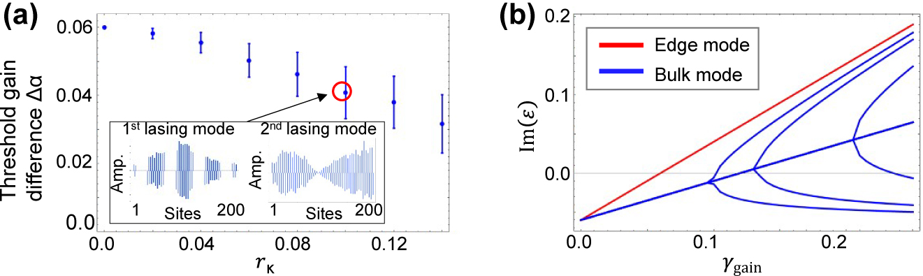
Robustness against inhomogeneous coupling strengths.
(a) Threshold gain difference between the first and second lasing modes as a function of coupling disorder r κ in a finite system consisting of n tri = 100 trivial and n topo = 101 topological cavities. The insets show representative mode profiles of the edge mode and bulk mode. Blue bars indicate the amplitudes on A-site. (b) Imaginary parts of eigenenergies of the system plotted as a function of supplied gain on A-site γ gain. The red and blue lines indicate the energy of the edge mode and bulk modes, respectively. The parameters used are κ 1 = 1.0, κ 2 = 1.04 and γ loss = 0.06. In (b), the randomness is r κ = 0.1.
3.2 Inhomogeneous site resonator frequencies
Next, we perform calculations for the cases with fluctuations in the resonance frequencies of the site resonators. We treat inhomogeneity in the resonator detunings Δ after subtracting a common frequency offset ω from the Hamiltonian in Eq. (1). For the perfectly regular case, Δ equals to zero for any mth resonator. We prepare 100 sets of random Δ’s distributed by Gaussian random variables with means Δ = 0 and the standard deviation r Δ. We introduce each set of generated random detunings in Eq. (1) and solve it by diagonalization for the system with κ 1 = 1.0 and κ 2 = 1.04. The ways of averaging the data for each r Δ and of its plot are the same as in the previous section.
Figure 5(a) shows the average
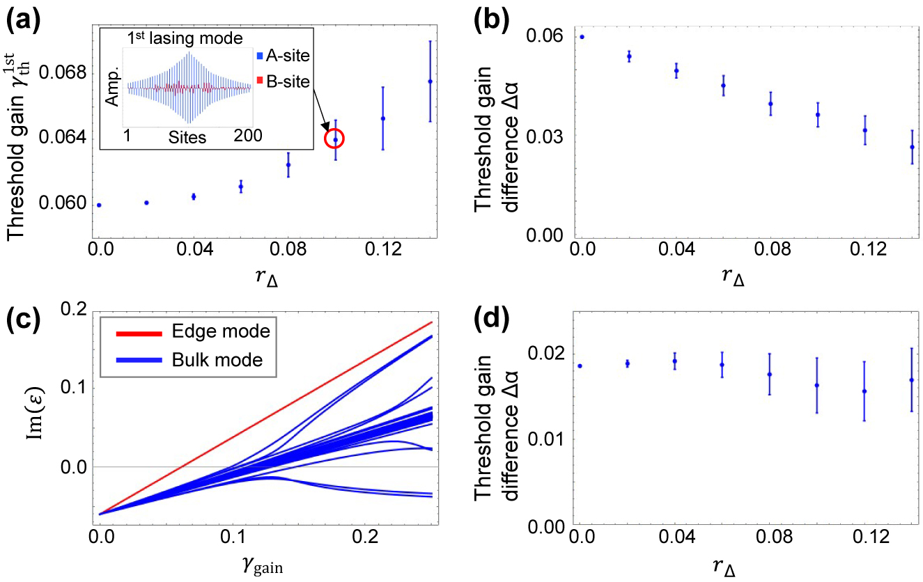
Robustness against inhomogeneous site resonator frequencies.
(a) Threshold gain of the first lasing mode as a function of strength of inhomogeneity in detuning r Δ in a finite system consisting of n tri = 100 trivial and n topo = 101 topological cavities. The inset shows a representative sample of the edge mode profile for r Δ = 0.1 where blue and red bars indicate the amplitudes on A-site and B-site, respectively. (b) Threshold gain difference Δα. (c) Imaginary parts of eigenenergies versus supplied gain on A-site γ gain. The red and blue lines indicate the energy of the edge mode and bulk modes, respectively. (d) Threshold gain difference Δα for the system with higher resonator loss of γ loss = 0.20. The coupling constant is κ 2/κ 1 = 1.04 and the loss is γ loss = 0.06 in (a)–(c) and γ loss = 0.20 in (d).
3.3 Next-nearest-neighbor cavity coupling
The discussion in Section 2 reveals that larger coupling strengths between the site resonators are advantageous for achieving a large Δα and thus for stable single mode lasing from a broadly-distributed topological edge mode. Cavity array designs for increasing the coupling strengths between the NN cavities may inevitably induce non-negligible next-nearest-neighbor (NNN) couplings, which will break chiral symmetry and thus could modify the performance of the laser device. In this section, we analyze the influence of NNN couplings on the investigated array laser.
Figure 6(a) explains the model we consider in this section. We define the ratio of the NNN couplings to NN couplings by a factor g:
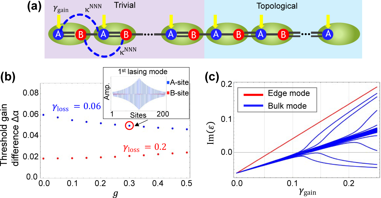
Robustness against next-nearest-neighbor cavity couplings.
(a) Extended tight-binding model for the topological laser, including the NNN couplings. NN couplings and NNN couplings are given as
4 Discussion
In this section, we discuss practically-achievable Δα for the topological array laser system that we discussed in the previous sections. The device under consideration consists of 201 site resonators with κ 1 = 1.0 and κ 2 = 1.04 so that it supports a broadly-distributed single topological edge mode. First, we estimate achievable strengths of κ 1 and κ 2 for conventional ridge-waveguide Fabry–Perot cavities based on GaAs/AlGaAs materials as an example. By choosing the ridge width of 1.4 µm, height of 1.6 µm and the gap between the ridges of 0.5 µm, the coupling strengths of ∼100 cm−1 is found to be possible by simulations using a finite element method. Thus, in the following discussion, we mainly consider the cases with κ 1 = 100 cm−1 and κ 2 = 104 cm−1. Note that, the fluctuation of κ 1 by 10% (corresponding to the case with r κ ∼ 0.1) can only happen when the ridge-to-ridge distance varies more than 150 nm. This level of fabrication imperfection is unlikely to occur using standard semiconductor processing technologies.
Once fixing the coupling strengths, the most critical factor determining Δα is the resonator loss. From Figure 3(c), it is possible to deduce a Δα of 0.019 for a loss of γ loss = 0.2. This case corresponds to Δα of 1.9 cm−1 when κ 1 = 100 cm−1 and thus γ loss = 20 cm−1 (Table 1), which is a moderate loss for typical semiconductor lasers with careful design and fabrication. Given the previously reported values for semiconductor lasers [20], Δα of 1.9 cm−1 could lead to stable single mode lasing in the device. As indicated in Figure 3(c), the maximum possible Δα can be obtained at the optimal point of the loss setting with γ loss = 0.06. For a system with κ 1 = 100 cm−1, these values are converted into Δα = 6 cm−1 and γ loss = 6 cm−1. While Δα of 6 cm−1 may be regarded as a sufficiently high for stable single mode lasing, the loss of γ loss = 6 cm−1 is too low when assuming the use of standard semiconductor lasers. In general, the optical loss in a semiconductor Fabry–Perot laser with zero carrier injection is composed of optical propagation loss, mirror loss and absorption in the active material. For a GaAs/AlGaAs ridge waveguide, the propagation loss can be reduced to about a few cm−1, while mirror loss becomes 6 cm−1 even for a 2 mm long cavity with a high reflection coating at a facet. Therefore, if including photon absorption in the unpumped active material, it is rather hard to realize the resonator optical loss of γ loss = 6 cm−1 to achieve the maximum possible Δα = 6 cm−1.
Values of Δα and their corresponding γ loss for two representative coupling strength κ 1.
| Maximum Δα | γ loss at maximum Δα | Δα at γ loss = 20 cm−1 | |
|---|---|---|---|
| κ 1 = 100 cm−1 | 6 cm−1 | 6 cm−1 | 1.9 cm−1 |
| κ 1 = 150 cm−1 | 9 cm−1 | 9 cm−1 | 4.2 cm−1 |
There are several possible ways to significantly reduce material absorption loss in semiconductor laser resonators for achieving large Δα. One straightforward way is to electrically pump lossy resonators. By introducing an additional gain of
It is also interesting to discuss other ways to improve Δα for large γ loss. As we have already observed, the introduction of NNN couplings is not largely detrimental to the single mode operation. Therefore, Δα can be enlarged by increasing NN couplings κ 1 as shown in Table 1. When κ 1 = 150 cm−1, Δα will be increased to 4.2 cm−1 even in the case of γ loss = 20 cm−1. Note that the increased NN couplings also relaxes the condition for achieving the maximum Δα. In such cases with large NN couplings, NNN and very long range couplings will become significant to determine the band structures, making the system more similar to photonic crystals where the long-range interactions are dominant. Designs of topological edge mode lasers using such structures toward high power output will be an interesting topic of further research.
Another interesting approach for increasing Δα is to use additional auxiliary lossy resonators. According to Figure 2(e) and (f), the mode profiles of the topological edge mode and the competing bulk mode differ largely in term of their envelope: the bulk mode shows a greater extent to the exterior of the system. Therefore, it could be possible to selectively load more loss on the bulk mode by terminating the system with auxiliary loss sites. We examined this idea for the system with κ
1 = 100 cm−1 by adding 10 lossy resonators with the same amount of loss for each termination, γ
loss = 20 cm−1. We observed an increase of Δα from 1.9 cm−1–2.4 cm−1 in this case. Note that this approach does not work well for the cases with low γ
loss less than 6 cm−1. In such cases, the competing bulk mode lases before γ
gain reaching
5 Summary
We investigated a fundamental model of broadly-distributed single-mode topological edge mode laser in the tight-binding approximation. We considered a sizable system consisted of 201 site resonators that potentially lead to a 10W-class laser by assuming that each resonator delivers ∼100 mW output power. We clarified the conditions for single-mode operation by calculating threshold gain differences Δα between the first lasing edge-mode and the second lasing bulk mode as an important factor for evaluating the stability of the single-mode operation. Below is a summary of what we found through the discussion: (a) under ideal conditions, Δα depends on the coupling strengths κ 1, κ 2 and the loss γ loss. There exists an optimal loss for each combination of the coupling strengths. For a system based on semiconductor lasers, large κ 1 and κ 2 with |κ 1/κ 2| ∼ 1 and small γ loss are most preferable for stable single mode lasing. (b) The single-mode operation of the edge mode is robust against disorders in coupling strengths and resonator detunings. (c) The topological laser is insensitive to the addition of resonator couplings among NNN sites. This suggests that one can design laser systems with large κ 1 and κ 2 while virtually ignoring the influence of the NNN couplings. (d) When assuming a set of realistic parameters for semiconductor lasers, Δα reaches a few cm−1, which could be large enough for stable single-mode lasing. To conclude, we provided significant insights for topological lasers in the context of realizing high power lasers. This work may open up a new pathway for practical applications of topological photonics.
Acknowledgements
The authors thank JSPS KAKENHI Grant No. JP21J40088, MEXT KAKENHI Grant Nos. JP15H05700, JP15H05868 and 17H06138, JST CREST (JPMJCR19T1) and NEDO. T.B. is supported by the National Natural Science Foundation of China (62071301); State Council of the People’s Republic of China (D1210036A); NSFC Research Fund for International Young Scientists (11850410426); NYU-ECNU Institute of Physics at NYU Shanghai; the Science and Technology Commission of Shanghai Municipality (19XD1423000); the China Science and Technology Exchange Center (NGA-16-004).
-
Author contribution: All the authors have accepted responsibility for the entire content of this submitted manuscript and approved submission.
-
Research funding: None declared.
-
Conflict of interest statement: The authors declare no conflicts of interest regarding this article.
References
[1] J. N. Walpole, “Semiconductor amplifiers and lasers with tapered gain regions,” Opt. Quant. Electron., vol. 28, p. 623, 1996. https://doi.org/10.1007/bf00411298.Search in Google Scholar
[2] P. Crump, G. . Erbert, H. Wenzel et al.., “Efficient high-power laser diodes,” IEEE J. Sel. Top. Quant. Electron., vol. 19, p. 1501211, 2013. https://doi.org/10.1109/jstqe.2013.2239961.Search in Google Scholar
[3] T. Y. Fan, “Laser beam combining for high-power, high-radiance sources,” IEEE J. Sel. Top. Quant. Electron., vol. 11, p. 567, 2005. https://doi.org/10.1109/jstqe.2005.850241.Search in Google Scholar
[4] D. Botez and D. E. Ackley, “Phase-locked arrays of semiconductor diode lasers,” IEEE Circ. Dev. Mag., vol. 2, pp. 8–17, 1986. https://doi.org/10.1109/mcd.1986.6311765.Search in Google Scholar
[5] A. F. Glova, “Phase locking of optically coupled lasers,” Quant. Electron., vol. 33, p. 283, 2003. https://doi.org/10.1070/qe2003v033n04abeh002415.Search in Google Scholar
[6] M. J. Miah, T. Kettler, K. Posilovic et al.., “1.9 W continuous-wave single transverse mode emission from 1060 nm edge-emitting lasers with vertically extended lasing area,” Appl. Phys. Lett., vol. 105, p. 151105, 2014. https://doi.org/10.1063/1.4898010.Search in Google Scholar
[7] P. Crump, S. Böldicke, C. M. Schultz, H. Ekhteraei, H. Wenzel, and G. Erbert, “Experimental and theoretical analysis of the dominant lateral waveguiding mechanism in 975 nm high power broad area diode lasers,” Semicond. Sci. Technol., vol. 27, p. 045001, 2012. https://doi.org/10.1088/0268-1242/27/4/045001.Search in Google Scholar
[8] J. Medina Pardell, R. Herrero, M. Botey, and K. Staliunas, “Non-Hermitian arrangement for stable semiconductor laser arrays,” Opt. Express, vol. 29, p. 23997, 2021. https://doi.org/10.1364/oe.425860.Search in Google Scholar PubMed
[9] A. M. Sarangan, W. Huang, T. Makino, and G. P. Li, “Dynamic single-transverse-mode properties of varying ridge width DFB laser arrays,” IEEE Photon. Technol. Lett., vol. 8, pp. 1305–1307, 1996. https://doi.org/10.1109/68.536636.Search in Google Scholar
[10] B. Sumpf, K.-H. Hasler, P. Adamiec et al.., “High-brightness quantum well tapered lasers,” IEEE J. Sel. Top. Quant. Electron., vol. 15, p. 1009, 2009. https://doi.org/10.1109/jstqe.2008.2010952.Search in Google Scholar
[11] X. Zhou, X. Ma, H. Qu et al.., “Extremely high-brightness tapered photonic crystal diode laser with narrow-emitting aperture,” Appl. Phys. Exp., vol. 12, p. 094004, 2019. https://doi.org/10.7567/1882-0786/ab2eee.Search in Google Scholar
[12] D. Naidoo, I. A. Litvin, and A. Forbes, “Brightness enhancement in a solid-state laser by mode transformation,” Optica, vol. 5, p. 836, 2018. https://doi.org/10.1364/optica.5.000836.Search in Google Scholar
[13] B. Qiu, S. D. McDougall, X. Liu, G. Bacchin, and J. H. Marsh, “Design and fabrication of low beam divergence and high kink-free power lasers,” IEEE J. Quant. Electron., vol. 41, p. 1124, 2005. https://doi.org/10.1109/jqe.2005.853359.Search in Google Scholar
[14] M. Achtenhagen, A. Hardy, and C. S. Harder, “Lateral mode discrimination and self-stabilization in ridge waveguide laser diodes,” IEEE Photon. Technol. Lett., vol. 18, p. 526, 2006. https://doi.org/10.1109/lpt.2005.863992.Search in Google Scholar
[15] H. Wenzel, F. Bugge, M. Dallmer et al.., “Fundamental-lateral mode stabilized high-power ridge-waveguide lasers with a low beam divergence,” IEEE Photon. Technol. Lett., vol. 20, p. 214, 2008. https://doi.org/10.1109/lpt.2007.913328.Search in Google Scholar
[16] M.-A. Miri, P. LiKamWa, and D. N. Christodoulides, “Large area single-mode parity-time-symmetric laser amplifiers,” Opt. Lett., vol. 37, pp. 764–766, 2012. https://doi.org/10.1364/ol.37.000764.Search in Google Scholar
[17] F. Liang, Z. J. Wong, R.-M. Ma, Y. Wang, and X. Zhang, “Single-mode laser by parity-time symmetry breaking,” Science, vol. 346, pp. 972–975, 2014. https://doi.org/10.1126/science.1258479.Search in Google Scholar PubMed
[18] M.-A. Miri and A. Alù, “Exceptional points in optics and photonics,” Science, vol. 363, p. eaar7709, 2019. https://doi.org/10.1126/science.aar7709.Search in Google Scholar PubMed
[19] M. P. Hokmabadi, N. S. Nye, R. El-Ganainy, D. N. Christodoulides, and M. Khajavikhan, “Supersymmetric laser arrays,” Science, vol. 363, p. 623, 2019. https://doi.org/10.1126/science.aav5103.Search in Google Scholar PubMed
[20] M. Yoshida, M. De Zoysa, K. Ishizaki et al.., “Double-lattice photonic-crystal resonators enabling high-brightness semiconductor lasers with symmetric narrow-divergence beams,” Nat. Mater., vol. 18, p. 121, 2019. https://doi.org/10.1038/s41563-018-0242-y.Search in Google Scholar PubMed
[21] B. Bahari, A. Ndao, F. Vallini, A. El Amili, Y. Fainman, and B. Kanté, “Nonreciprocal lasing in topological cavities of arbitrary geometries,” Science, vol. 358, pp. 636–640, 2017. https://doi.org/10.1126/science.aao4551.Search in Google Scholar PubMed
[22] P. St-Jean, E. V. GalopinGoblot, A. Lemaître et al.., “Lasing in topological edge states of a one-dimensional lattice,” Nat. Photonics, vol. 11, p. 651, 2017. https://doi.org/10.1038/s41566-017-0006-2.Search in Google Scholar
[23] M. A. Bandres, S. Wittek, H. Gal et al.., “Topological insulator laser: experiments,” Science, vol. 359, p. eaar4005, 2018. https://doi.org/10.1126/science.aar4005.Search in Google Scholar PubMed
[24] H. Gal, M. A. Bandres, Y. Lumer et al.., “Topological insulator laser: theory,” Science, vol. 359, p. eaar4003, 2018. https://doi.org/10.1126/science.aar4003.Search in Google Scholar PubMed
[25] M. Parto, S. Wittek, H. Hodaei et al.., “Edge-mode lasing in 1D topological active arrays,” Phys. Rev. Lett., vol. 120, p. 113901, 2018. https://doi.org/10.1103/physrevlett.120.113901.Search in Google Scholar
[26] H. Zhao, P. Miao, M. H. Teimourpour et al.., “Topological hybrid silicon microlasers,” Nat. Commun., vol. 9, p. 981, 2018. https://doi.org/10.1038/s41467-018-03434-2.Search in Google Scholar PubMed PubMed Central
[27] S. Klembt, T. H. Harder, O. A. Egorov et al.., “Exciton-polariton topological insulator,” Nature, vol. 562, pp. 552–556, 2018. https://doi.org/10.1038/s41586-018-0601-5.Search in Google Scholar PubMed
[28] Y. Ota, R. Katsumi, K. Watanabe, S. Iwamoto, and Y. Arakawa, “Topological photonic crystal nanocavity laser,” Commun. Phys., vol. 1, p. 86, 2018. https://doi.org/10.1038/s42005-018-0083-7.Search in Google Scholar
[29] C. Han, M. Lee, S. . Callard, C. Seassal, and H. Jeon, “Lasing at topological edge states in a photonic crystal L3 nanocavity dimer array,” Light Sci. Appl., vol. 8, p. 40, 2019. https://doi.org/10.1038/s41377-019-0149-7.Search in Google Scholar PubMed PubMed Central
[30] Z.-K. Shao, H.-Z. Chen, S. Wang et al.., “A high-performance topological bulk laser based on band-inversion-induced reflection,” Nat. Nanotechnol., vol. 15, p. 67, 2020. https://doi.org/10.1038/s41565-019-0584-x.Search in Google Scholar PubMed
[31] Y. Zeng, U. Chattopadhyay, B. Zhu et al.., “Electrically pumped topological laser with valley edge modes,” Nature, vol. 578, pp. 246–250, 2020. https://doi.org/10.1038/s41586-020-1981-x.Search in Google Scholar PubMed
[32] W. Zhang, X. Xie, H. Hao et al.., “Low-threshold topological nanolasers based on the second-order corner state,” Light Sci. Appl., vol. 9, p. 109, 2020. https://doi.org/10.1038/s41377-020-00352-1.Search in Google Scholar PubMed PubMed Central
[33] C. M. Han abdKang and H. Jeon, “Lasing at multidimensional topological states in a two-dimensional photonic crystal structure,” ACS Photonics, vol. 7, no. 8, p. 2027, 2020. https://doi.org/10.1021/acsphotonics.0c00357.Search in Google Scholar
[34] Z.-Q. Yang, Z.-K. Shao, H.-Z. Chen, X.-R. Mao, and R.-M. Ma, “Spin-momentum-locked edge mode for topological vortex lasing,” Phys. Rev. Lett., vol. 125, p. 013903, 2020. https://doi.org/10.1103/PhysRevLett.125.013903.Search in Google Scholar PubMed
[35] W. Noh, H. Nasari, H.-M. Kim et al.., “Experimental demonstration of single-mode topological valley-hall lasing at telecommunication wavelength controlled by the degree of asymmetry,” Opt. Lett., vol. 45, pp. 4108–4111, 2020. https://doi.org/10.1364/ol.399053.Search in Google Scholar PubMed
[36] L. Lu, J. D. Joannopoulos, and M. Soljačić, “Topological photonics,” Nat. Photonics, vol. 8, p. 821, 2014. https://doi.org/10.1038/nphoton.2014.248.Search in Google Scholar
[37] A. B. Khanikaev and G. Shvets, “Two-dimensional topological photonics,” Nat. Photonics, vol. 11, pp. 763–773, 2017. https://doi.org/10.1038/s41566-017-0048-5.Search in Google Scholar
[38] T. Ozawa and H. M. Price, et al.., “Topological photonics,” Rev. Mod. Phys., vol. 91, p. 015006, 2019. https://doi.org/10.1103/revmodphys.91.015006.Search in Google Scholar
[39] Y. Ota, K. Takata, T. Ozawa et al.., “Active topological photonics,” Nanophotonics, vol. 9, p. 547, 2020. https://doi.org/10.1515/nanoph-2019-0376.Search in Google Scholar
[40] D. Smirnova, D. Leykam, Y. Chong, and Y. Kivshar, “Nonlinear topological photonics,” Appl. Phys. Rev., vol. 7, p. 021306, 2020. https://doi.org/10.1063/1.5142397.Search in Google Scholar
[41] S. Iwamoto, Y. Ota, and Y. Arakawa, “Recent progress in topological waveguides and nanocavities in a semiconductor photonic crystal platform,” Opt. Mater. Express, vol. 11, pp. 319–337, 2021. https://doi.org/10.1364/ome.415128.Search in Google Scholar
[42] R. Jackiw and C. Rebbi, “Solitons with fermion number 1/2,” Phys. Rev. D, vol. 13, pp. 3398–3409, 1976. https://doi.org/10.1103/physrevd.13.3398.Search in Google Scholar
[43] Y. Hatsugai, “Chern number and edge states in the integer quantum hall effect,” Phys. Rev. Lett., vol. 71, pp. 3697–3700, 1993. https://doi.org/10.1103/physrevlett.71.3697.Search in Google Scholar PubMed
[44] Y. Hatsugai, “Edge states in the integer quantum hall effect and the Riemann surface of the bloch function,” Phys. Rev. B, vol. 48, pp. 11851–11862, 1993. https://doi.org/10.1103/physrevb.48.11851.Search in Google Scholar PubMed
[45] S.-L. Chua, L. Lu, J. Bravo-Abad, J. D. Joannopoulos, and M. Soljačić, “Larger-area single-mode photonic crystal surface-emitting lasers enabled by an accidental Dirac point,” Opt. Lett., vol. 39, pp. 2072–2075, 2014. https://doi.org/10.1364/ol.39.002072.Search in Google Scholar PubMed
[46] X. Gao, L. Yang, H. Lin et al.., “Dirac-vortex topological cavities,” Nat. Nanotechnol., vol. 15, p. 1012, 2020. https://doi.org/10.1038/s41565-020-0773-7.Search in Google Scholar PubMed
[47] Y. Ota, F. Liu, R. Katsumi et al.., “Photonic crystal nanocavity based on a topological corner state,” Optica, vol. 6, pp. 786–789, 2019. https://doi.org/10.1364/optica.6.000786.Search in Google Scholar
[48] H.-R. Kim, M.-S. Hwang, D. Smirnova, K.-Y. Jeong, Y. Kivshar, and H.-G. Park, “Multipolar lasing modes from topological corner states,” Nat. Commun., vol. 11, p. 5758, 2020. https://doi.org/10.1038/s41467-020-19609-9.Search in Google Scholar PubMed PubMed Central
[49] S. Weimann, M. Kremer, Y. Plotnik et al.., “Topologically protected bound states in photonic parity-time-symmetric crystals,” Nat. Mater., vol. 16, p. 433, 2017. https://doi.org/10.1038/nmat4811.Search in Google Scholar PubMed
[50] K. Takata and M. Notomi, “PT-symmetric coupled-resonator waveguide based on buried heterostructure nanocavities,” Phys. Rev. Appl., vol. 7, p. 054023, 2017. https://doi.org/10.1103/physrevapplied.7.054023.Search in Google Scholar
[51] K. Takata and M. Notomi, “Photonic topological insulating phase induced solely by gain and loss,” Phys. Rev. Lett., vol. 121, p. 213902, 2018. https://doi.org/10.1103/physrevlett.121.213902.Search in Google Scholar PubMed
[52] C. Poli, M. Bellec, U. Kuhl, F. Mortessagne, and H. Schomerus, “Selective enhancement of topologically induced interface states in a dielectric resonator chain,” Nat. Commun., vol. 6, p. 6710, 2015. https://doi.org/10.1038/ncomms7710.Search in Google Scholar PubMed PubMed Central
[53] S. Malzard and H. Schomerus, “Nonlinear mode competition and symmetry protected power oscillations in topological lasers,” New J. Phys., vol. 20, p. 063044, 2018. https://doi.org/10.1088/1367-2630/aac9e0.Search in Google Scholar
[54] J. C. Cartledge and A. F. Elrefaie, “Threshold gain difference requirements for nearly single-longitudinal-mode lasers,” J. Lightwave Technol., vol. 8, pp. 704–715, 1990. https://doi.org/10.1109/50.54478.Search in Google Scholar
[55] N. Henmi, Y. Koizumi, M. Yamaguchi, M. Shikada, and I. Mito, “The influence of directly modulated DFB LD sub-mode oscillation on long-span transmission system,” J. Lightwave Technol., vol. 6, pp. 636–642, 1988. https://doi.org/10.1109/50.4048.Search in Google Scholar
[56] J. K. Asbóth, L. Oroszlány, and A. Pályi, “A short course on topological insulators: band structure and edge states in one and two dimensions,” in Lecture Notes in Physics, vol. 919, Heidelberg, Germany, Springer, 2016.10.1007/978-3-319-25607-8Search in Google Scholar
[57] J. Zak, “Berry’s phase for energy bands in solids,” Phys. Rev. Lett., vol. 62, pp. 2747–2750, 1989. https://doi.org/10.1103/physrevlett.62.2747.Search in Google Scholar PubMed
[58] H. Schomerus, “Topologically protected midgap states in complex photonic lattices,” Opt. Lett., vol. 38, p. 1912, 2013. https://doi.org/10.1364/ol.38.001912.Search in Google Scholar
[59] Ş. K. Özdemir, S. Rotter, F. Nori, and L. Yang, “Parity-time symmetry and exceptional points in photonics,” Nat. Mater., vol. 18, p. 783, 2019. https://doi.org/10.1038/s41563-019-0304-9.Search in Google Scholar PubMed
[60] R. El-Ganainy, K. G. Makris, M. Khajavikhan, Z. H. Musslimani, S. Rotter, and D. N. Christodoulides, “Non-Hermitian physics and PT symmetry,” Nat. Phys., vol. 14, p. 11, 2018. https://doi.org/10.1038/nphys4323.Search in Google Scholar
[61] B. Peng, S. Kaya Özdemir, F. Lei et al.., “Parity-time-symmetric whispering-gallery microcavities,” Nat. Phys., vol. 10, p. 394, 2014. https://doi.org/10.1038/nphys2927.Search in Google Scholar
[62] I. Mondragon-Shem, T. L. Hughes, J. Song, and E. Prodan, “Topological criticality in the chiral-symmetric AIII class at strong disorder,” Phys. Rev. Lett., vol. 113, p. 046802, 2014. https://doi.org/10.1103/PhysRevLett.113.046802.Search in Google Scholar PubMed
[63] B. Pérez-González, M. Bello, Á. Gómez-León, and G. Platero, “Interplay between long-range hopping and disorder in topological systems,” Phys. Rev. B, vol. 99, p. 035146, 2019. https://doi.org/10.1103/physrevb.99.035146.Search in Google Scholar
[64] C. Jürß and D. Bauer, “High-harmonic generation in Su–Schrieffer–Heeger chains,” Phys. Rev. B, vol. 99, p. 195428, 2019. https://doi.org/10.1103/physrevb.99.195428.Search in Google Scholar
[65] M. Scollon, and M. P. Kennett, “Persistence of chirality in the Su–Schrieffer–Heeger model in the presence of on-site disorder,” Phys. Rev. B, vol. 101, p. 144204, 2020. https://doi.org/10.1103/physrevb.101.144204.Search in Google Scholar
[66] Y. Arakawa and H. Sakaki, “Multidimensional quantum well laser and temperature dependence of the threshold current,” Appl. Phys. Lett., vol. 40, p. 939, 1982. https://doi.org/10.1063/1.92959.Search in Google Scholar
[67] S. Matsuo, T. Fujii, K. Hasebe, K. Takeda, T. Sato, and T. Kakitsuka, “Directly modulated buried heterostructure DFB laser on SiO2/Si substrate fabricated by regrowth of InP using bonded active layer,” Opt. Express, vol. 22, p. 12139, 2014. https://doi.org/10.1364/oe.22.012139.Search in Google Scholar PubMed
© 2022 Natsuko Ishida et al., published by De Gruyter, Berlin/Boston
This work is licensed under the Creative Commons Attribution 4.0 International License.
Articles in the same Issue
- Frontmatter
- Editorial
- Editorial on special issue: “Metamaterials and plasmonics in Asia”
- Reviews
- Waveguide effective plasmonics with structure dispersion
- Graphene-based plasmonic metamaterial for terahertz laser transistors
- Recent advances in metamaterials for simultaneous wireless information and power transmission
- Multi-freedom metasurface empowered vectorial holography
- Nanophotonics-inspired all-silicon waveguide platforms for terahertz integrated systems
- Optical metasurfaces towards multifunctionality and tunability
- The perspectives of broadband metasurfaces and photo-electric tweezer applications
- Free-form optimization of nanophotonic devices: from classical methods to deep learning
- Optical generation of strong-field terahertz radiation and its application in nonlinear terahertz metasurfaces
- Responsive photonic nanopixels with hybrid scatterers
- Research Articles
- Efficient modal analysis of plasmonic nanoparticles: from retardation to nonclassical regimes
- Molecular chirality detection using plasmonic and dielectric nanoparticles
- Vortex radiation from a single emitter in a chiral plasmonic nanocavity
- Reconfigurable Mach–Zehnder interferometer for dynamic modulations of spoof surface plasmon polaritons
- Manipulating guided wave radiation with integrated geometric metasurface
- Comparison of second harmonic generation from cross-polarized double-resonant metasurfaces on single crystals of Au
- Rotational varifocal moiré metalens made of single-crystal silicon meta-atoms for visible wavelengths
- Meta-lens light-sheet fluorescence microscopy for in vivo imaging
- All-metallic high-efficiency generalized Pancharatnam–Berry phase metasurface with chiral meta-atoms
- Drawing structured plasmonic field with on-chip metalens
- Negative refraction in twisted hyperbolic metasurfaces
- Anisotropic impedance surfaces activated by incident waveform
- Machine–learning-enabled metasurface for direction of arrival estimation
- Intelligent electromagnetic metasurface camera: system design and experimental results
- High-efficiency generation of far-field spin-polarized wavefronts via designer surface wave metasurfaces
- Terahertz meta-chip switch based on C-ring coupling
- Resonance-enhanced spectral funneling in Fabry–Perot resonators with a temporal boundary mirror
- Dynamic inversion of planar-chiral response of terahertz metasurface based on critical transition of checkerboard structures
- Terahertz 3D bulk metamaterials with randomly dispersed split-ring resonators
- BST-silicon hybrid terahertz meta-modulator for dual-stimuli-triggered opposite transmission amplitude control
- Gate-tuned graphene meta-devices for dynamically controlling terahertz wavefronts
- Dual-band composite right/left-handed metamaterial lines with dynamically controllable nonreciprocal phase shift proportional to operating frequency
- Highly suppressed solar absorption in a daytime radiative cooler designed by genetic algorithm
- All-optical binary computation based on inverse design method
- Exciton-dielectric mode coupling in MoS2 nanoflakes visualized by cathodoluminescence
- Broadband wavelength tuning of electrically stretchable chiral photonic gel
- Spatio-spectral decomposition of complex eigenmodes in subwavelength nanostructures through transmission matrix analysis
- Scattering asymmetry and circular dichroism in coupled PT-symmetric chiral nanoparticles
- A large-scale single-mode array laser based on a topological edge mode
- Far-field optical imaging of topological edge states in zigzag plasmonic chains
- Omni-directional and broadband acoustic anti-reflection and universal acoustic impedance matching