Negative refraction in twisted hyperbolic metasurfaces
-
Yi Liu
 ,
Quan Xu
,
Quan Xu

Abstract
Hyperbolic metasurfaces with unique dispersion properties can manipulate light–matter interactions according to the demands. However, due to their inherent physical properties, topological transitions (flat bands) exist only in the orthogonal directions, which greatly limit their application. Here, we unveil rich dispersion engineering and topological transitions in hyperbolic metasurfaces. Based on the effective medium theory, the rotation matrix is introduced into the dispersion relation to explain the distorted energy band diagrams, iso-frequency contours and higher-order multi-dipoles of the novel twisted metasurfaces, thereby forming multi-directional topological transitions and surface plasmon polariton propagation. Furthermore, we develop an integrated model to realize new dual-channel negative refraction and nondiffraction negative refraction. The phenomena observed in the experiments match well with the simulations, which proves that the designed metasurfaces make new types of negative refraction possible and will help to overcome the diffraction limit. The hyperbolic metasurfaces presented here exhibit exceptional capabilities for designing microscopes with a super lens at the molecular level, concealment of military aircraft, invisibility cloaks and other photonic devices with higher transmission efficiency.
1 Introduction
Topological dispersion in the momentum space, widely existing in hyperbolic metamaterials [1], [2], [3], [4], [5], [6], linear-crossing metamaterials [7], [8], [9], epsilon-near-zero media [10], [11], [12], and magic-angle graphene superlattices [13], [14], [15], [16], [17], results in a number of interesting optical phenomena such as self-collimating transport [18], [19], [20], anomalous wave propagation [21], [22], [23], negative refraction and so on [24], [25], [26], [27], [28]. Due to their low propagation loss and simple manufacturing process, hyperbolic metasurfaces (HMSs) have attracted substantial interest in manipulating surface plasmon polariton (SPP) propagation [21, 29]. Besides, based on their 2D characteristics HMSs show exceptional capabilities in planar optoelectronic devices [30], [31], [32] and have great potential in super-resolution imaging [33], [34], [35], wearable devices [36], [37], [38], [39], invisible cloaks [40, 41], etc. Recently, topological transition metasurfaces have attracted enormous research interests [42], [43], [44]. One of the most fascinating features of HMSs is that they have a topological dispersion exhibiting a flat line at the transition point, and such a property enables HMS to support propagating high-k modes and possess enhanced photonic density of states (hence a large Purcell factor), and promises fascinating applications, such as large field enhancement, sensing, and sub-diffraction imaging [3, 4, 39]. However, in the case of flat bands in the first Brillouin zone, the SPP transmission is self-collimated and confined in the orthogonal directions due to the intrinsic physical nature. Can the tuning of transport directions of surface waves be realized in HMSs?
Adjustable iso-frequency contours (IFCs) are a straightforward and effective manner in the manipulation of the light–matter interactions. However, recent developments in metasurfaces have concentrated on the control of polarization, phase and amplitude [45], [46], [47], [48]. In particular, tuning the shape of hyperbolic dispersion in an active manner determines the frequency of the phase transition. For example, in the microwave regime, 2D transmission lines [8, 49, 50], multilayers [51, 52], and metallic nanowire structures [29, 53] can be used to obtain topological transition in IFCs by varying the loaded capacitance and inductance. In the infrared regime, active tuning of the IFCs can be achieved by changing the loaded voltage of graphene or graphene dielectric multilayer structures, but the interlayer voltage is difficult to adjust artificially, which leads to great inconvenience to experimental measurements [54, 55]. Unlike the active manipulation mentioned above, there are also many examples of passive control. Multilayer fishnets can be tuned by changing the thickness of different layers or choosing different wavelengths in the visible regime [56, 57], and the research scope also has been extended to the terahertz and microwave regimes, which depends on the adjustment of IFCs by changing the permittivity, permeability, shape, or structural parameters of the metal–dielectric–metal structures and the metal–dielectric structures [22, 42, 58, 59].
In this article, an ultrathin integrated metasurface with hyperbolic dispersion is proposed and experimentally demonstrated. We take the unique electromagnetic characteristics such as energy bands and IFCs as starting points. From the dispersion properties, it can be found that topological transition frequencies only exist in the orthogonal directions. Here, an efficient method is proposed to control the multi-directional topological transition. When the proposed hyperbolic cells are rotated counterclockwise, the metasurface exhibits a higher-order coupling mode, thereby breaking the band overlap, and a new series of self-collimation frequencies emerge. At the same time, the corresponding energy bands and IFCs have also been rotated counterclockwise, so the metasurface promises a new platform to mimic diverse surface wave propagation processes. Finally, we have designed an integrated metasurface prototype to manipulate dual-channel negative refraction and nondiffraction negative refraction phenomena, whose unique transmission properties will benefit the hyperlenses, stealth materials and wearable devices.
2 Simulation and discussion
2.1 Structural design
The sketch of a single unit of the designed metasurfaces is schematically shown in the left panel of Figure 1, where the parameters are: p = 9 mm, a = 4.5 mm, b = 2.6 mm, c = d = 1.6 mm, and e = 0.56 mm. To fulfill the requirement of rotation in the following steps, the parameters must meet the condition:

Schematic diagram of the proposed twisted HMSs consisting of a dielectric/Cu bilayer, where p = 9 mm, a = 4.5 mm, b = 2.6 mm, c = d = 1.6 mm, and e = 0.56 mm, and the counterclockwise rotation angle of the unit cell is α.
2.2 Basic physical properties
Based on the effective medium theory (EMT), for the electric HMSs, the relative permeability
The subscripts xx and yy denote the components parallel to the x and y axes, respectively. The dispersion relation of the HMSs can be determined by substituting Eq. (1) into the Maxwell’s equations. In particular, for the TM mode, the dispersion relation can be written as:
where k
0 is the wave-vector in free space, and k
x, k
y are the x and y components of the wave-vector, respectively. Then, the rotation matrix
The relative permittivity tensor in Eq. (1) should be rewritten as:
In this case, the dispersion relation can be derived as:
where
We can clearly see that when the structural unit rotates 90°, the IFC rotates 90° accordingly. However, there are nondiagonal terms in the permittivity tensor when α = 0–90°:
Let us take α = 30° as an example:
At this time, the IFCs are no longer ideal ellipses, straight lines or hyperbolae, but have the feature of distortion. The rotation of the unit cell will strongly modify the IFC shape. As a result, the propagation properties of electromagnetic waves will become more diverse by tuning the rotational angle. The twisted models can not only apply to the engineering of SPP transport but also have potential applications in the design of new active devices.
To gain a better understanding of the electromagnetic characteristics of the presented HMS, we numerically calculated its band diagrams using the eigenvalue module of the commercial software Computer Simulation Technology (CST) along the highly symmetrical points in the first Brillouin zone. Based on the equation k = π × θ/180p, the values of k x and k y are obtained, and the 3D energy band diagrams/IFCs of the first two energy bands in the first Brillouin zone are presented in Figure 2(a)–(d) for different rotation angles, while the inset in Figure 2(a) indicates the first Brillouin zone and the highly symmetrical points. It is obvious that when the primitive cell rotates 0–45° counterclockwise, the IFCs rotate counterclockwise and the band overlap appears in the second IFC when α = 45°. Additionally, there are varying degrees of distortion. The presence of the extensive overlap means that there are no Lifshitz-like continuous topological transitions in the band diagrams, so the flat band is difficult to be independently excited. Fortunately, there are two ways to break the overlap to obtain a new self-collimation frequency: one is to break the extensive overlap between different energy bands, and the other is to generate a new resonance frequency excited by the incident electromagnetic waves [42]. Therefore, a new self-collimation frequency can be obtained with the appearance of new resonance modes by the counterclockwise rotation around the z-axis, which will simultaneously break the symmetry in the x and y directions. For example, when the unit cells rotate counterclockwise around the z axis, a tilted self-collimation frequency appears when α = 45°. Another appealing feature is that the extreme points (red areas) are no longer at the high symmetry points, which originates from the primitive cell rotation and the lattice no longer having a reflection surface, so the extreme points are not necessary at the boundary of the Brillouin zone. In order to study the underlying mechanism of these changes, we discuss the transmission spectra in the following.

The 3D energy band diagrams/IFCs of the first two bands in the first Brillouin zone when the rotation angles are (a) 0° (the inset in the band diagram illustrates the first Brillouin zone and the highly symmetrical points), (b) 15°, (c) 30°, and (d) 45°, respectively. The unit of the frequency values in the IFCs is GHz.
As shown in Figure 3(a) and (b), a slight red shift appears in the transmission dip as the model rotates when the incident light is polarized along the x direction, and the coupling in the x-direction also rotates counterclockwise. However, a new dip appears at 12.77 GHz as an octapole when the model rotates 45°. Figure 3(c) and (d) exhibit, respectively, new resonance modes of the hexapole (13.26 GHz for α = 15° and 13.10 GHz for α = 30°) and octapole interactions along the y direction when the incident light is polarized in the y-direction. The higher-order coupling indicates that the metasurface manipulates the interaction between light and matter in new ways, and thus the suppression of radiation loss will be achieved. Besides, because the higher-order multi-dipoles and new types of interactions between the x and y directions are excited with the rotation of the unit cells, not only the energy bands rotate accordingly, but distortions of the band diagrams also appear. Therefore, the rotation operation can be used as an effective solution to obtain flat lines without distortion in the IFC, so as to achieve self-collimation frequencies.
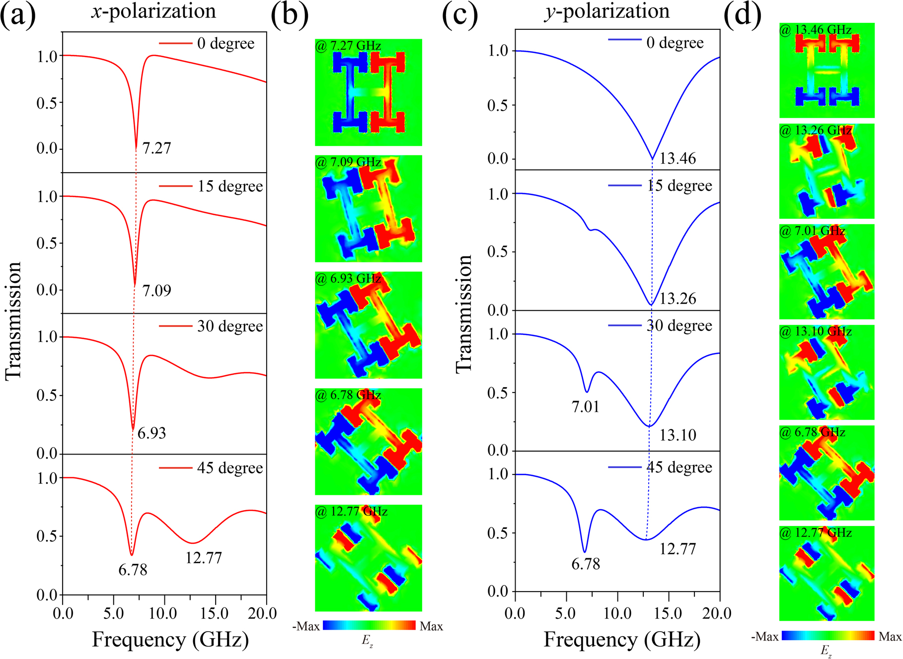
Transmittance spectra and Ez field distributions. (a and c) Normalized transmittance spectra when the incident waves are polarized in the x and y directions, respectively. (b and d) E z field distributions on the surface of the unit cells at the resonance valleys corresponding to (a) and (c).
Based on the normalized transmittance spectra discussed above, we make a quantitatively characterization of the permittivity by treating the proposed twisted HMSs as homogeneous anisotropic effective-medium slabs, and the effective permittivity can be obtained by the S-parameter retrieval process [62], [63], [64]. The S matrix can be written as:
where h is the thickness of the dielectric slab. The effective permittivity ε can be calculated by
The corresponding calculation results are plotted in Figure 4. When the rotation angle α = 0° and
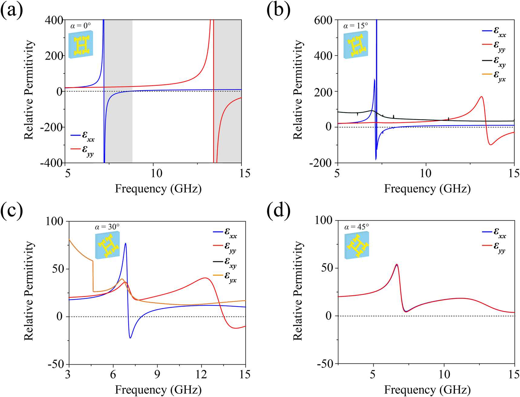
Relative permittivity obtained from EMT when the counterclockwise rotation angles of the sample are (a) α = 0°, (b) α = 15°, (c) α = 30°, and (d) α = 45°, respectively. The gray regions in (a) exhibit the hyperbolic IFCs predicted by EMT.
2.3 Multi-directional SPP propagation
As shown in the right panel in Figure 1, a microwave dipole, resonating in the z direction, can generate surface waves on the surface of the electromagnetic HMSs. The CST time-domain solver was used to simulate the electric field E
z
distributions of the rotated model (α = 0–45°) at the respective transition frequencies of the first two energy bands as depicted in Figure 5. As the surface plasmon group velocity is perpendicular to the IFC

The twisted samples and E z distributions at the transition frequencies when the counterclockwise rotation angles of the samples are (a) α = 0°, (b) α = 15°, (c) α = 30°, and (d) α = 45°, respectively. β 1 and β 2 are the counterclockwise rotation angles of the propagation directions of the SPPs with respect to the x and y axes, respectively.
2.4 Negative refraction
Due to the rotational symmetry, compared with the model whose rotation angle is α, the IFC of the model with a rotation angle of α +90° is relatively rotated by 90°. By combining different twisted meta-resonators, SPP propagation can be redirected at the interface at will. For example, observation of negative refraction phenomenon is presented in Figure 6 when the SPPs traverse an interface between two metasurfaces whose rotation angles are 45° (unit A) and 135° (unit B), respectively. We select two typical negative refraction phenomena and the corresponding IFCs for analyzing the underlying mechanism. As illustrated in Figure 6, the bottom half of the metasurface consists of arrays of units A (29 × 8 unit cells) while the top half array is made up of units B (29 × 8 unit cells). The electric dipole is located at the center of the boundary at the bottom side.
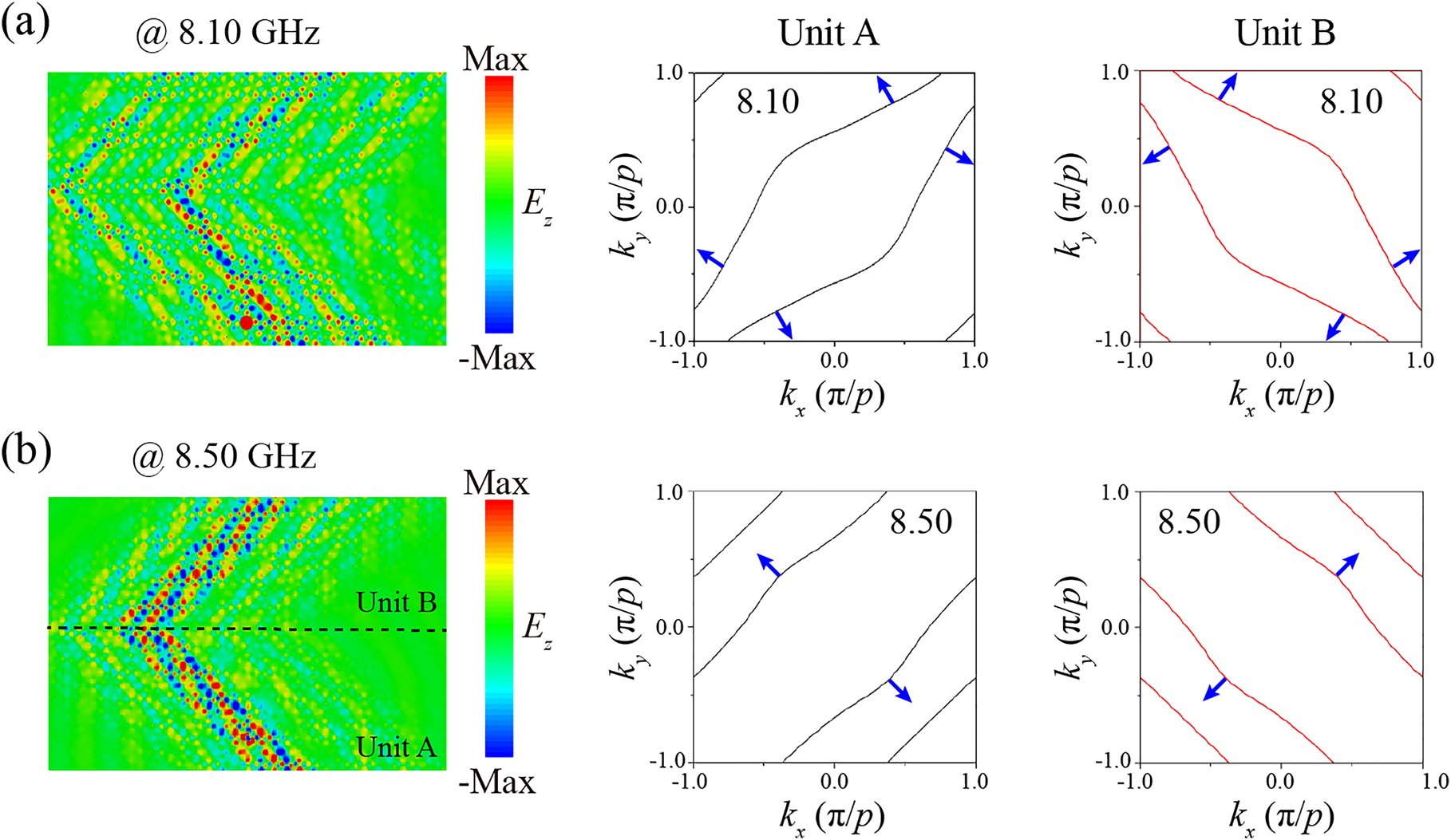
Calculated E z distributions in the xy plane at 0.05 mm above the integrated structure and the corresponding IFCs at (a) 8.10 GHz and (b) 8.50 GHz, respectively.
Interestingly, at 8.10 GHz, as the unit A has a hyperbolic IFC, the excited SPPs transmit along two crossing straight lines. Therefore, for units B, the IFC rotates 90° relative to that of units A, and the surface waves rotate 90° as well. The surface waves can reach the interface along two transmission paths, and they travel in the directions perpendicular to the original trajectories after passing through the interface, forming a dual-channel negative refraction phenomenon. On the other hand, at 8.50 GHz, the IFCs of units A are four straight lines with a rotational angle of 45° with respect to the horizontal direction. Therefore, the surface waves transmit along the diagonal directions without diffraction. At this time, the photon density of states reaches a maximum, which is expressed as nondiffraction negative refraction. The proposed HMS thus provides a new method for negative refraction phenomena, anomalous wave propagation, asymmetric transmission, etc. And there will be a wider range of applications in the areas of surface optoelectronic device integration, sensors, hyperlenses, and in-plane beam steering.
3 Experimental results
As shown in Figure 7, a metasurface consisting of 29 × 16 unit cells and excitation units (total size 279 × 162 mm) was fabricated. The dielectric slab was made of F4BM300 with a permittivity of 3.0 and tgδ ≤ 7 × 10⁻⁴ at 10 GHz. The metallic patterns were printed on the slab with 35 µm thick copper and the organic solderability preservatives antioxidation process were employed on the metal surface to prevent oxidation. The structure was designed with p = 9 mm, a = 4.5 mm, b = 2.6 mm, c = d = 1.6 mm, and e = 0.56 mm. Microstrip lines with a width of 2.4 mm and a length of 13.5 mm was designed around the structure to match the impedance of the network analyzer in order to excite surface waves. The impedance was calculated to be 50.99 Ω through ‘microstrip calculation’, which matched the impedance of the network analyzer of 50 Ω, and simulations further proved that the influence of the microstrip lines on the electric distribution could be neglected. In order to calculate and verify the effective medium property of the realistic metasurfaces, we measured the transmission and reflection data of the fabricated HMS (the counterclockwise rotation angle was α = 45°) as shown in Figure 7(b). Here, the experimental process led to some deviations: there was a small angle between the receiving port and the incident port when measuring the reflection spectrum, the excitation signal was scattered into air, and the noise in the experiment especially had a greater impact on the calculation process. Overall, the measured results match well with the simulation, and we can assume that the permittivity calculated from the realistic metasurface coincides with the theoretical calculations (Figure 7(c)).
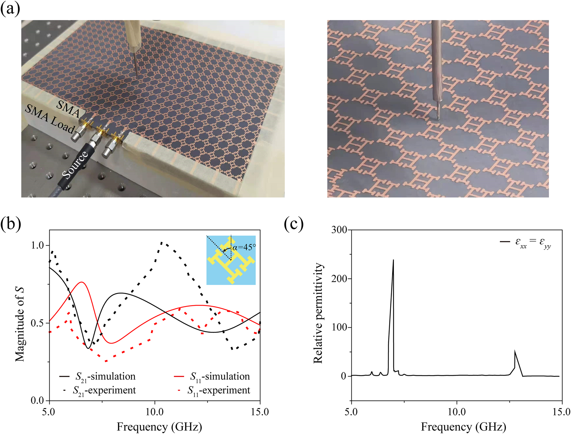
Experimental results. (a) Details of the measurement process in the microwave regime. (b) Transmission and reflection spectra of the measurements (points) and simulations (lines) when the source was polarized along the y axis. (c) Relative permittivity obtained from the measurements.
In the experiment, an SMA connector was used to produce a microwave dipole between the substrate and the metal structure to excite the SPPs, as shown in Figure 7. Since the dipole is similar to a spherical wave, in order to solve the problem of the coupling between the source and the surrounding structures, we placed two SMA loads with a nominal impedance of 50 Ω and frequency range of 0–18 GHz on both sides of the dipole. An antenna was used to detect the z-oriented electric field at 0.05 mm above the metasurface with a step of 2 mm along both the x-axis and the y-axis by a 3D translation platform. Compared with the E z distributions in Figure 6, the measured electric fields depicted in Figure 8 agree well with our simulations. Similarly, a dual-channel phenomenon appears at 9.03 GHz. When the frequency is near 9.34 GHz, the dual-channel phenomenon disappears, and the maximum photon density of states is reached at this time, which means that nondiffracting negative refraction was realized. The experimental bandwidths of the dual-channel and nondiffraction negative refraction of the surface waves are 0.25 and 0.19 GHz, respectively. In the simulation, they are, respectively, 0.26 and 0.20 GHz, which shows excellent consistence with the experiments. However, in this situation, the results show that the corresponding frequencies between the simulations and measurements have a slight shift, which might result from the fabrication error. For example, the realistic permittivity is hard to determine, which will result in enormous loss and largely affect the working frequencies, and the thickness will also have an error of ±0.02–±0.04 mm. Overall, the measurements agree with the simulations, showing the validity of the proposed twisted HMS and the unusual negative refraction, which can be used to improve the transmission efficiency of hyperlenses and other new photonic devices.

Measured E z distributions in the xy plane at 0.05 mm above the integrated structure at (a) 9.03 GHz and (b) 9.34 GHz, respectively.
4 Conclusions
We theoretically and experimentally studied a series of twisted HMSs, which were proved to deliver an efficient way to realize dual-channel and nondiffracting negative refraction. The internal mechanism of the distorted energy bands and IFCs were also analyzed. Such unique rotated HMSs will greatly increase the application range of surface waves in nondiffraction transmission, anomalous wave propagation, negative refraction, and super-resolution imaging, and offer new opportunities in developing integrated circuits and plasmonic devices.
Funding source: National Key Research and Development Program of China
Award Identifier / Grant number: 2017YFA0701004
Funding source: China Postdoctoral Science Foundation
Award Identifier / Grant number: 2020M680877
Award Identifier / Grant number: 2020TQ0224
Funding source: Applied Basic Research Project of Shanxi Province
Award Identifier / Grant number: 201801D221161
Funding source: National Natural Science Foundation of China
Award Identifier / Grant number: 61735012
Award Identifier / Grant number: 61775159
Award Identifier / Grant number: 61805129
Award Identifier / Grant number: 61875150
Award Identifier / Grant number: 62005193
-
Author contribution: Y. L. performed the theory, simulations, experiments, and completed the first draft of the manuscript. C. O. proposed the original idea and supervised the entire project. Q. X. and X. S. conducted the theory and experiment. J. M. and J. Z. helped on the theory. W. Z. supervised the project. Y. L., Z. T., J. G., L. L. and J. H. commented on the manuscript. All the authors discussed the results.
-
Research funding: This work was supported by the National Key Research and Development Program of China (Grant No. 2017YFA0701004), the National Natural Science Foundation of China (Grant Nos. 61775159, 61735012, 61875150, 61805129, 62005193), and China Postdoctoral Science Foundation (Grant Nos. 2020TQ0224 and 2020M680877), and Applied Basic Research Project of Shanxi Province (Grant No. 201801D221161).
-
Conflict of interest statement: The authors declare no conflicts of interest.
References
[1] H. N. Krishnamoorthy, Z. Jacob, E. Narimanov, I. Kretzschmar, and V. M. Menon, “Topological transitions in metamaterials,” Science, vol. 336, pp. 205–209, 2012. https://doi.org/10.1126/science.1219171.Search in Google Scholar PubMed
[2] S. S. Kruk, Z. J. Wong, E. Pshenay-Severin, et al.., “Magnetic hyperbolic optical metamaterials,” Nat. Commun., vol. 7, pp. 1–7, 2016. https://doi.org/10.1038/ncomms11329.Search in Google Scholar PubMed PubMed Central
[3] Z. W. Guo, H. T. Jiang, and H. Chen, “Hyperbolic metamaterials: from dispersion manipulation to applications,” J. Appl. Phys., vol. 127, 2020, Art no. 071101. https://doi.org/10.1063/1.5128679.Search in Google Scholar
[4] P. Huo, S. Zhang, Y. Liang, Y. Lu, and T. Xu, “Hyperbolic metamaterials and metasurfaces: fundamentals and applications,” Adv. Opt. Mater., vol. 7, 2019, Art no. 1801616. https://doi.org/10.1002/adom.201801616.Search in Google Scholar
[5] P. Zheng, Q. Xu, X. Su, et al.., “Anomalous wave propagation in topological transition metasurfaces,” Adv. Opt. Mater., vol. 7, 2019, Art no. 1801483. https://doi.org/10.1002/adom.201801483.Search in Google Scholar
[6] Y. H. Yang, P. F. Qin, B. Zheng, et al.., “Magnetic hyperbolic metasurface: concept, design, and applications,” Adv. Sci., vol. 5, 2018, Art no. 1801495. https://doi.org/10.1002/advs.201801495.Search in Google Scholar PubMed PubMed Central
[7] Z. Guo, H. Jiang, K. Zhu, Y. Sun, Y. Li, and H. Chen, “Focusing and super-resolution with partial cloaking based on linear-crossing metamaterials,” Phys. Rev. Appl., vol. 10, 2018, Art no. 064048. https://doi.org/10.1103/physrevapplied.10.064048.Search in Google Scholar
[8] Z. Guo, H. Jiang, and H. Chen, “Abnormal wave propagation in tilted linear‐crossing metamaterials,” Adv. Photonics Res., vol. 2, 2021, Art no. 2000071. https://doi.org/10.1002/adpr.202000071.Search in Google Scholar
[9] Z. Guo, H. Jiang, and H. Chen, “Abnormal wave propagation of high-k modes in tilted linear-crossing metamaterials,” Optics, vol. 2008, 2020, Art no. 03012.10.1002/adpr.202000071Search in Google Scholar
[10] P. N. Dyachenko, S. Molesky, A. Y. Petrov, et al.., “Controlling thermal emission with refractory epsilon-near-zero metamaterials via topological transitions,” Nat. Commun., vol. 7, pp. 1–8, 2016. https://doi.org/10.1038/ncomms11809.Search in Google Scholar PubMed PubMed Central
[11] K. Yu, Z. Guo, H. Jiang, and H. Chen, “Loss-induced topological transition of dispersion in metamaterials,” J. Appl. Phys., vol. 119, 2016, Art no. 203102. https://doi.org/10.1063/1.4952378.Search in Google Scholar
[12] M. A. Othman, C. Guclu, and F. Capolino, “Graphene–dielectric composite metamaterials: evolution from elliptic to hyperbolic wavevector dispersion and the transverse epsilon-near-zero condition,” J. Nanophotonics, vol. 7, 2013, Art no. 073089. https://doi.org/10.1117/1.jnp.7.073089.Search in Google Scholar
[13] F. He, Y. Zhou, Z. Ye, et al.., “Moiré patterns in 2D materials: a review,” ACS Nano, vol. 15, pp. 5944–5958, 2021. https://doi.org/10.1021/acsnano.0c10435.Search in Google Scholar PubMed
[14] G. Hu, M. Wang, Y. Mazor, C. W. Qiu, and A. Alù, “Tailoring light with layered and moiré metasurfaces,” Trends Chem., vol. 3, pp. 342–358, 2021. https://doi.org/10.1016/j.trechm.2021.02.004.Search in Google Scholar
[15] H. Herzig Sheinfux, and F. H. Koppens, “The rise of twist-optics,” Nano Lett, vol. 20, pp. 6935–6936, 2020. https://doi.org/10.1021/acs.nanolett.0c03175.Search in Google Scholar PubMed
[16] G. Hu, A. Krasnok, Y. Mazor, C. W. Qiu, and A. Alù, “Moiré hyperbolic metasurfaces,” Nano Lett, vol. 20, pp. 3217–3224, 2020. https://doi.org/10.1021/acs.nanolett.9b05319.Search in Google Scholar PubMed
[17] Y. Cao, V. Fatemi, S. Fang, et al.., “Unconventional superconductivity in magic-angle graphene superlattices,” Nature, vol. 556, pp. 43–50, 2018. https://doi.org/10.1038/nature26160.Search in Google Scholar PubMed
[18] B. Stein, E. Devaux, C. Genet, and T. Ebbesen, “Self-collimation of surface plasmon beams,” Opt. Lett., vol. 37, pp. 1916–1918, 2012. https://doi.org/10.1364/ol.37.001916.Search in Google Scholar
[19] L. Zhang, W. Zhang, G. Wang, et al.., “Broadband self-collimating phenomenon in a low-loss hybrid plasmonic photonic crystal,” Appl. Opt., vol. 57, pp. 829–833, 2018. https://doi.org/10.1364/ao.57.000829.Search in Google Scholar
[20] S. S. Oh, S. G. Lee, J. E. Kim, and H. Y. Park, “Self-collimation phenomena of surface waves in structured perfect electric conductors and metal surfaces,” Opt Express, vol. 15, pp. 1205–1210, 2007. https://doi.org/10.1364/oe.15.001205.Search in Google Scholar PubMed
[21] Y. Yang, L. Jing, L. Shen, et al.., “Hyperbolic spoof plasmonic metasurfaces,” NPG Asia Mater., vol. 9, 2017, Art no. e428. https://doi.org/10.1038/am.2017.158.Search in Google Scholar
[22] Y. Liu and X. Zhang, “Metasurfaces for manipulating surface plasmons,” Appl. Phys. Lett., vol. 103, 2013, Art no. 141101. https://doi.org/10.1063/1.4821444.Search in Google Scholar
[23] Y. Yang, L. Shen, L. Jing, et al.., “Ultrathin metasurface with topological transition for manipulating spoof surface plasmon polaritons,” Optics, vol. 1604, 2016, Art no. 05830.Search in Google Scholar
[24] J. B. Pendry, “Negative refraction,” Contemp. Phys., vol. 45, pp. 191–202, 2004. https://doi.org/10.1080/00107510410001667434.Search in Google Scholar
[25] J. Pendry, “A chiral route to negative refraction,” Science, vol. 306, pp. 1353–1355, 2004. https://doi.org/10.1126/science.1104467.Search in Google Scholar PubMed
[26] G. V. Eleftheriades, and K. G. Balmain, Negative-refraction Metamaterials: Fundamental Principles and Applications, Canada, John Wiley & Sons, 2005.10.1002/0471744751Search in Google Scholar
[27] J. Yao, Z. Liu, Y. Liu, et al.., “Optical negative refraction in bulk metamaterials of nanowires,” Science, vol. 321, p. 930, 2008. https://doi.org/10.1126/science.1157566.Search in Google Scholar PubMed
[28] V. Agranovich, Y. Shen, R. Baughman, and A. Zakhidov, “Linear and nonlinear wave propagation in negative refraction metamaterials,” Phys. Rev. B, vol. 69, 2004, Art no. 165112. https://doi.org/10.1103/physrevb.69.165112.Search in Google Scholar
[29] Y. Bao, S. Zu, W. Liu, L. Zhou, X. Zhu, and Z. Fang, “Revealing the spin optics in conic-shaped metasurfaces,” Phys. Rev. B, vol. 95, 2017, Art no. 081406. https://doi.org/10.1103/physrevb.95.081406.Search in Google Scholar
[30] A. V. Kildishev, A. Boltasseva, and V. M. Shalaev, “Planar photonics with metasurfaces,” Science, vol. 339, p. 6125, 2013. https://doi.org/10.1126/science.1232009.Search in Google Scholar PubMed
[31] A. A. High, R. C. Devlin, A. Dibos, et al.., “Visible-frequency hyperbolic metasurface,” Nature, vol. 522, pp. 192–196, 2015. https://doi.org/10.1038/nature14477.Search in Google Scholar PubMed
[32] W. Ma, Z. Huang, X. Bai, P. Zhan, and Y. Liu, “Dual-band light focusing using stacked graphene metasurfaces,” ACS Photonics, vol. 4, pp. 1770–1775, 2017. https://doi.org/10.1021/acsphotonics.7b00351.Search in Google Scholar
[33] O. Takayama, and A. V. Lavrinenko, “Optics with hyperbolic materials,” J. Opt. Soc. Am. B, vol. 36, pp. F38–F48, 2019. https://doi.org/10.1364/josab.36.000f38.Search in Google Scholar
[34] K. A. Willets, A. J. Wilson, V. Sundaresan, and P. B. Joshi, “Super-resolution imaging and plasmonics,” Chem. Rev., vol. 117, pp. 7538–7582, 2017. https://doi.org/10.1021/acs.chemrev.6b00547.Search in Google Scholar PubMed
[35] L. Shen, H. Wang, R. Li, Z. Xu, and H. Chen, “Hyperbolic-polaritons-enabled dark-field lens for sensitive detection,” Sci. Rep., vol. 7, pp. 1–8, 2017. https://doi.org/10.1038/s41598-017-07576-z.Search in Google Scholar PubMed PubMed Central
[36] H. I. Lin, K. C. Shen, S. Y. Lin, et al.., “Transient and flexible hyperbolic metamaterials on freeform surfaces,” Sci. Rep., vol. 8, pp. 1–10, 2018. https://doi.org/10.1038/s41598-018-27812-4.Search in Google Scholar PubMed PubMed Central
[37] C. Wang and Z. Zhang, “Broadband optical absorption enhancement in hybrid organic–inorganic perovskite metasurfaces,” AIP Adv., vol. 11, 2021, Art no. 025107. https://doi.org/10.1063/5.0037367.Search in Google Scholar
[38] W. T. Chen, A. Y. Zhu, J. Sisler, Z. Bharwani, and F. Capasso, “A broadband achromatic polarization-insensitive metalens consisting of anisotropic nanostructures,” Nat. Commun., vol. 10, pp. 1–7, 2019. https://doi.org/10.1038/s41467-019-08305-y.Search in Google Scholar PubMed PubMed Central
[39] J. Hu, S. Bandyopadhyay, Y. H. Liu, and L. Y. Shao, “A review on metasurface: from principle to smart metadevices,” Front. Phys., vol. 8, p. 502, 2021. https://doi.org/10.3389/fphy.2020.586087.Search in Google Scholar
[40] Y. Yang, L. Jing, B. Zheng, et al.., “Full‐polarization 3D metasurface cloak with preserved amplitude and phase,” Adv. Mater., vol. 28, pp. 6866–6871, 2016. https://doi.org/10.1002/adma.201600625.Search in Google Scholar PubMed
[41] C. Sheng, H. Liu, H. Chen, and S. Zhu, “Definite photon deflections of topological defects in metasurfaces and symmetry-breaking phase transitions with material loss,” Nat. Commun., vol. 9, pp. 1–8, 2018. https://doi.org/10.1038/s41467-018-06718-9.Search in Google Scholar PubMed PubMed Central
[42] C. D. Hu, X. X. Wu, R. Tong, et al.., “A metasurface with bidirectional hyperbolic surface modes and position-sensing applications,” NPG Asia Mater., vol. 10, pp. 417–428, 2018. https://doi.org/10.1038/s41427-018-0047-0.Search in Google Scholar
[43] C. Wu, D. Bergman, L. Balents, and S. D. Sarma, “Flat bands and Wigner crystallization in the honeycomb optical lattice,” Phys. Rev. Lett., vol. 99, 2007, Art no. 070401. https://doi.org/10.1103/PhysRevLett.99.070401.Search in Google Scholar PubMed
[44] V. Apaja, M. Hyrkäs, and M. Manninen, “Flat bands, Dirac cones, and atom dynamics in an optical lattice,” Phys. Rev. A, vol. 82, 2010, Art no. 041402. https://doi.org/10.1103/physreva.82.041402.Search in Google Scholar
[45] N. K. Grady, J. E. Heyes, D. R. Chowdhury, et al.., “Terahertz metamaterials for linear polarization conversion and anomalous refraction,” Science, vol. 340, pp. 1304–1307, 2013. https://doi.org/10.1126/science.1235399.Search in Google Scholar PubMed
[46] L. Liang, M. Qi, J. Yang, et al.., “Anomalous terahertz reflection and scattering by flexible and conformal coding metamaterials,” Adv. Opt. Mater., vol. 3, pp. 1374–1380, 2015. https://doi.org/10.1002/adom.201500206.Search in Google Scholar
[47] C. Menzel, C. Helgert, C. Rockstuhl, et al.., “Asymmetric transmission of linearly polarized light at optical metamaterials,” Phys. Rev. Lett., vol. 104, 2010, Art no. 253902. https://doi.org/10.1103/physrevlett.104.253902.Search in Google Scholar PubMed
[48] J. M. Hao, Y. Yuan, L. X. Ran, et al.., “Manipulating electromagnetic wave polarizations by anisotropic metamaterials,” Phys. Rev. Lett., vol. 99, 2007, Art no. 063908. https://doi.org/10.1103/PhysRevLett.99.063908.Search in Google Scholar PubMed
[49] G. Goubau, “Surface waves and their application to transmission lines,” J. Appl. Phys., vol. 21, pp. 1119–1128, 1950. https://doi.org/10.1063/1.1699553.Search in Google Scholar
[50] P. C. Magnusson, G. C. Alexander, V. K. Tripathi, and A. Weisshaar, Transmission Lines and Wave Propagation, Boca Raton, Florida, USA, CRC Press, 2017.Search in Google Scholar
[51] Z. Su, Y. Wang, and H. Shi, “Dynamically tunable directional subwavelength beam propagation based on photonic spin Hall effect in graphene-based hyperbolic metamaterials,” Opt Express, vol. 28, pp. 11309–11318, 2020. https://doi.org/10.1364/oe.390717.Search in Google Scholar
[52] Z. Guo, H. Jiang, and H. Chen, “Linear-crossing metamaterials mimicked by multi-layers with two kinds of single negative materials,” JPhys Photonics, vol. 2, 2020, Art no. 011001. https://doi.org/10.1088/2515-7647/ab5ecb.Search in Google Scholar
[53] A. Belardini, F. Pannone, G. Leahu, et al.., “Asymmetric transmission and anomalous refraction in metal nanowires metasurface,” J. Eur. Opt. Soc., vol. 7, 2012, Art no. 12051. https://doi.org/10.2971/jeos.2012.12051.Search in Google Scholar
[54] Y. C. Chang, C. H. Liu, C. H. Liu, et al.., “Realization of mid-infrared graphene hyperbolic metamaterials,” Nat. Commun., vol. 7, pp. 1–7, 2016. https://doi.org/10.1038/ncomms10568.Search in Google Scholar PubMed PubMed Central
[55] Z. Su, and Y. Wang, “Anisotropic photonics topological transition in hyperbolic metamaterials based on black phosphorus,” Nanomaterials, vol. 10, p. 1694, 2020. https://doi.org/10.3390/nano10091694.Search in Google Scholar PubMed PubMed Central
[56] P. Tapsanit, M. Yamashita, C. Otani, S. Krongsuk, and C. Ruttanapun, “Closed-form formulae of effective parameters of hyperbolic metamaterial made by stacked hole-array layers working at terahertz or microwave radiation,” J. Opt. Soc. Am. B, vol. 34, pp. 1930–1936, 2017. https://doi.org/10.1364/josab.34.001930.Search in Google Scholar
[57] P. Tapsanit, M. Yamashita, C. Otani, S. Krongsuk, and C. Ruttanapuna, “Closed-form formulae of hyperbolic metamaterial made by stacked hole-array layers working at terahertz or microwave radiation,” Optics, vol. 1704, 2017, Art no. 03614.10.1364/JOSAB.34.001930Search in Google Scholar
[58] H. Li, C. Hu, X. Zhou, W. Lu, B. Hou, and W. Wen, “Conical diffraction from type-II Dirac point at metasurfaces,” Europhys. Lett., vol. 130, 2020, Art no. 17007. https://doi.org/10.1209/0295-5075/130/17007.Search in Google Scholar
[59] C. Hu, Z. Li, R. Tong, et al.., “Type-II Dirac photons at metasurfaces,” Phys. Rev. Lett., vol. 121, 2018, Art no. 024301. https://doi.org/10.1103/PhysRevLett.121.024301.Search in Google Scholar PubMed
[60] P. Shekhar, J. Atkinson, and Z. Jacob, “Hyperbolic metamaterials: fundamentals and applications,” Nano Converg., vol. 1, pp. 1–17, 2014. https://doi.org/10.1186/s40580-014-0014-6.Search in Google Scholar PubMed PubMed Central
[61] V. P. Drachev, V. A. Podolskiy, and A. V. Kildishev, “Hyperbolic metamaterials: new physics behind a classical problem,” Opt Express, vol. 21, pp. 15048–15064, 2013. https://doi.org/10.1364/oe.21.015048.Search in Google Scholar PubMed
[62] D. R. Smith, S. Schultz, P. Markoš, and C. M. Soukoulis, “Determination of effective permittivity and permeability of metamaterials from reflection and transmission coefficients,” Phys. Rev. B, vol. 65, 2002, Art no. 195104. https://doi.org/10.1103/physrevb.65.195104.Search in Google Scholar
[63] X. Liu, T. Starr, A. F. Starr, and W. J. Padilla, “Infrared spatial and frequency selective metamaterial with near-unity absorbance,” Phys. Rev. Lett., vol. 104, 2010, Art no. 207403. https://doi.org/10.1103/physrevlett.104.207403.Search in Google Scholar
[64] X. Chen, T. M. Grzegorczyk, B. I. Wu, J. PachecoJr, and J. A. Kong, “Robust method to retrieve the constitutive effective parameters of metamaterials,” Phys. Rev. E, vol. 70, no. 1, 2004, Art no. 016608. https://doi.org/10.1103/PhysRevE.70.016608.Search in Google Scholar PubMed
[65] R. W. Ziolkowski, “Design, fabrication, and testing of double negative metamaterials,” IEEE Trans. Antennas Propag., vol. 51, no. 7, pp. 1516–1529, 2003. https://doi.org/10.1109/tap.2003.813622.Search in Google Scholar
[66] Y. Yang, P. Qin, X. Lin, et al.., “Type-I hyperbolic metasurfaces for highly-squeezed designer polaritons with negative group velocity,” Nat. Commun., vol. 10, pp. 1–7, 2019. https://doi.org/10.1038/s41467-019-10027-0.Search in Google Scholar PubMed PubMed Central
© 2021 Yi Liu et al., published by De Gruyter, Berlin/Boston
This work is licensed under the Creative Commons Attribution 4.0 International License.
Articles in the same Issue
- Frontmatter
- Editorial
- Editorial on special issue: “Metamaterials and plasmonics in Asia”
- Reviews
- Waveguide effective plasmonics with structure dispersion
- Graphene-based plasmonic metamaterial for terahertz laser transistors
- Recent advances in metamaterials for simultaneous wireless information and power transmission
- Multi-freedom metasurface empowered vectorial holography
- Nanophotonics-inspired all-silicon waveguide platforms for terahertz integrated systems
- Optical metasurfaces towards multifunctionality and tunability
- The perspectives of broadband metasurfaces and photo-electric tweezer applications
- Free-form optimization of nanophotonic devices: from classical methods to deep learning
- Optical generation of strong-field terahertz radiation and its application in nonlinear terahertz metasurfaces
- Responsive photonic nanopixels with hybrid scatterers
- Research Articles
- Efficient modal analysis of plasmonic nanoparticles: from retardation to nonclassical regimes
- Molecular chirality detection using plasmonic and dielectric nanoparticles
- Vortex radiation from a single emitter in a chiral plasmonic nanocavity
- Reconfigurable Mach–Zehnder interferometer for dynamic modulations of spoof surface plasmon polaritons
- Manipulating guided wave radiation with integrated geometric metasurface
- Comparison of second harmonic generation from cross-polarized double-resonant metasurfaces on single crystals of Au
- Rotational varifocal moiré metalens made of single-crystal silicon meta-atoms for visible wavelengths
- Meta-lens light-sheet fluorescence microscopy for in vivo imaging
- All-metallic high-efficiency generalized Pancharatnam–Berry phase metasurface with chiral meta-atoms
- Drawing structured plasmonic field with on-chip metalens
- Negative refraction in twisted hyperbolic metasurfaces
- Anisotropic impedance surfaces activated by incident waveform
- Machine–learning-enabled metasurface for direction of arrival estimation
- Intelligent electromagnetic metasurface camera: system design and experimental results
- High-efficiency generation of far-field spin-polarized wavefronts via designer surface wave metasurfaces
- Terahertz meta-chip switch based on C-ring coupling
- Resonance-enhanced spectral funneling in Fabry–Perot resonators with a temporal boundary mirror
- Dynamic inversion of planar-chiral response of terahertz metasurface based on critical transition of checkerboard structures
- Terahertz 3D bulk metamaterials with randomly dispersed split-ring resonators
- BST-silicon hybrid terahertz meta-modulator for dual-stimuli-triggered opposite transmission amplitude control
- Gate-tuned graphene meta-devices for dynamically controlling terahertz wavefronts
- Dual-band composite right/left-handed metamaterial lines with dynamically controllable nonreciprocal phase shift proportional to operating frequency
- Highly suppressed solar absorption in a daytime radiative cooler designed by genetic algorithm
- All-optical binary computation based on inverse design method
- Exciton-dielectric mode coupling in MoS2 nanoflakes visualized by cathodoluminescence
- Broadband wavelength tuning of electrically stretchable chiral photonic gel
- Spatio-spectral decomposition of complex eigenmodes in subwavelength nanostructures through transmission matrix analysis
- Scattering asymmetry and circular dichroism in coupled PT-symmetric chiral nanoparticles
- A large-scale single-mode array laser based on a topological edge mode
- Far-field optical imaging of topological edge states in zigzag plasmonic chains
- Omni-directional and broadband acoustic anti-reflection and universal acoustic impedance matching