Omni-directional and broadband acoustic anti-reflection and universal acoustic impedance matching
-
Ku Im
 and
Q-Han Park
and
Q-Han Park


Abstract
The mechanism of the perfect anti-reflection of acoustic waves, regardless of frequency and incident angle, is presented. We show that reflections at a planar interface between two different acoustic media can be removed by adding a nonlocal metamaterial that compensates for the impedance mismatch. The properties required of a nonlocal metamaterial are explicitly specified through spatio-temporally dispersive mass density and bulk modulus. We analyze the characteristics of spatio-temporal dispersion according to the thickness of the matching layer. We discuss the issue of the total internal reflection caused by conventional matching layers and explain how our nonlocal matching layer avoids this. The practical design of our nonlocal layer using metamaterials is explained. The omni-directional frequency-independent behavior of the proposed anti-reflection matching layer is confirmed through explicit numerical calculation using the finite element method, and comparisons made to the conventional quarter-wave matching layer approach.
1 Introduction
Acoustic waves reflect at the interface between two different media, due to the discontinuity of acoustic impedance. This reflection is often undesirable as it can damage wave generators or medium materials through the formation of constructive interference inside media [1], [2], [3], [4]. In addition, acoustic reflection is a hindrance for industrial applications such as sonography, acoustic power transfer, and perfect acoustic absorption, for which the maximum transmission of acoustic energy is preferred [5], [6], [7], [8], [9], [10]. Various efforts have been made to remove unwanted reflection by applying a matching layer made of porous materials [7], single- or multi-layered materials [11, 12], graded index materials [13], [14], [15], and acoustic metamaterials [3, 16, 17]. Although these matching layers compensate for the impedance mismatch, their performance has previously been restricted to a specific frequency or incident angle.
The Mason’s equivalent circuit model [18] and the Krimholtz, Leedom, and Matthaei transmission line method [19] have been utilized to develop anti-reflection matching layers for broader frequency band operations [20]. However, this bandwidth broadening was achieved at the cost of unnecessary acoustic wave absorption inside the matching layer, which reduced the efficiency of energy transfer [4]. Moreover, since the circuit model does not consider the incident angle, it does not help in the design of acoustic impedance matching layers for varied incidence angles, and this limits its application to the non-destructive wide-angle inspection of industrial materials [21]. In short, so far, no systematic approach has been devised for removing the impedance mismatch between two different acoustic media regardless of incident angle and frequency.
Here, we derive the material condition for universal acoustic impedance matching (UAIM) from acoustic wave equations, allowing us to remove unwanted reflection regardless of frequencies and incident angles. Inspired by the electromagnetic universal impedance matching theory [22], we first reformulate the acoustic wave equation in terms of impedance function and then express the material parameters explicitly as functions of the impedance. We show that, in order to obtain omni-directional and broadband acoustic anti-reflection, the impedance of a matching layer should vary with respect to incident angles and frequencies, thereby resulting in a matching layer featuring spatially and temporally dispersive material parameters. For a specific UAIM example, we present a homogeneous UAIM layer and compare its anti-reflective performance to a conventional quarter-wave anti-reflection (QAR) matching layer. We also address the issue of the total internal reflection that could be caused by conventional matching layers and explain how our UAIM matching layer avoids it. We also demonstrate the perfect anti-reflective performance of the UAIM layer both analytically and numerically.
2 Theory of UAIM
2.1 Acoustic wave equation in terms of impedance function
Acoustic waves are a special case of elastic medium waves that are characterized according to the deformation and stress fields obeying the generalized Hooke’s law and Newton’s second law [23]. An isotropic linear elastic medium characterized by the bulk modulus and shear modulus supports both compressional and shear waves. When the bulk modulus far outweighs the shear modulus, the shear wave is negligible, and the dominant compressional wave is known as the acoustic wave. In this acoustic approximation, the stress and deformation fields are described by the acoustic pressure field
where
As shown in Figure 1, we consider a linear and time-independent medium possessing rotational symmetry about the
where
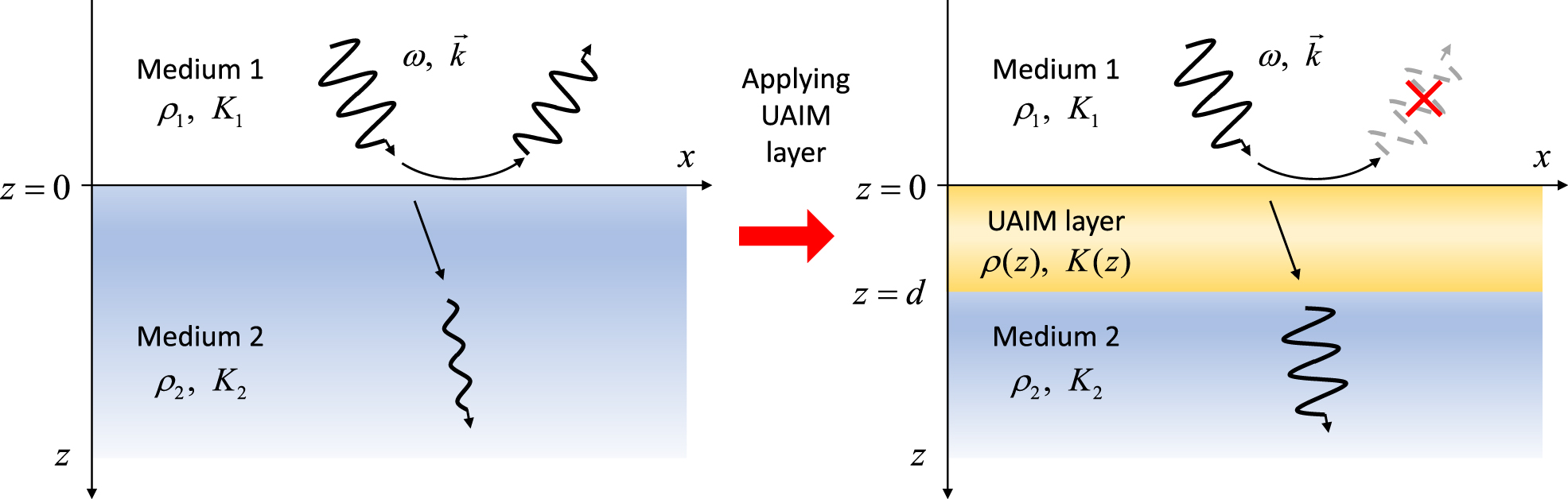
UAIM layer enabling the complete removal of acoustic reflection regardless of frequencies and incident angles.
The velocity components are directly obtained from pressure field by
where in the last step, we introduced impedance
If the medium is lossless with real parameters
This result is significant. We have achieved a direct correspondence between the material parameters
2.2 Reflection-zero conditions and a constant UAIM layer
A prominent application of the direct inverse scattering scheme is the perfect anti-reflection of an acoustic wave. We seek for a universal acoustic impedance matching (UAIM) layer, which can remove reflection regardless of wave frequency and incidence angle. Consider an acoustic wave propagating through the planar interface between two different homogeneous media of mass densities
where
Eliminating
where
For any
One simple case of UAIM is when the material parameters
with the newly defined constants
Boundary condition (2.2.5) can be satisfied by choosing
where
3 Results and discussion
3.1 Spatial and temporal dispersions of the constant UAIM layer
The UAIM layer with constant material parameters in (2.2.8) exhibits both spatial and temporal dispersion. To understand the dispersive behavior, we consider the example of a constant UAIM layer between the PZT4 ceramic (

Material dispersions (A) Mass density ρ and (B) bulk modulus κ for the constant UAIM layer with respect to θ 1 and the ratio γ. Here, ρ 1 and ρ 2 are the mass densities of the PZT4 ceramic and water, respectively.
If
The temporal dispersion of the normal incidence case (
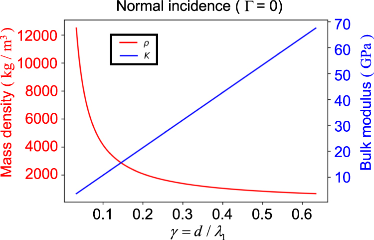
Temporal dispersion for the normal incidence.
To focus on the spatial dispersion behavior, we fix wavelength

Spatial dispersion depending on the thickness to wavelength ratio of (A) γ = 1/8, (B) γ = 1/4, (C) γ = 1/2, and (D) γ = 1.
So far, we have described the properties of the spatio-temporal dispersion of a UAIM layer without specific design rules. Here, we only point out that metamaterials are intrinsically nonlocal materials. Recently, Liu et al. proposed a non-local acoustic metamaterial [24] possessing unusual spatio-temporal dispersion inspired by the shifted spatial dispersion occurring in electromagnetic media [25]. By adjusting the parameters of the unit cell metamaterial structure, the equal frequency contours of a crystal band structure can be manipulated so as to achieve the required dispersions for the constant UAIM layer.
3.2 Total internal reflection
The thickness
where

Reflection contour plot of (A) QAR of d = c 1/10f t, (B) QAR of d = c 1/3f t, and (C) constant UAIM of d = c 1/3f t, where f t = 1.5 MHz is the target frequency of the QAR.

Reflection spectra of sound wave for varying incident angles with and without matching layers via COMSOL simulation. (A) Schematic design of the aUAIM layer. (B) Reflection spectra for normal incidence. (C) Angle dependence of the reflectance at frequency f = 1.7 MHz. Solid lines in (B) and (C) refer to the analytic solutions for each case, and squares represent the simulation results (black: bare substrate, blue: QAR, red: aUAIM). (D)–(F) Contour plots of reflectance versus incident angle and frequency for the substrate without matching layer (D), with the ideal QAR layer (E) and with the aUAIM layer (F).
3.3 Realistic design of UAIM layer and its anti-reflective performance
Material parameters for UAIM introduced in (2.2.8) are nonlocal and divergent in the limit of vanishing layer thickness and 90° glancing. Practically, if we avoid these extreme cases and make a moderate restriction of frequency band and angle range, we can design an approximate universal acoustic impedance matching (aUAIM) layer utilizing metamaterials. Figure 6 shows a schematic design of aUAIM layer and its performance in anti-reflection. The double-layer structure, with two layers sandwiching a subwavelength gap layer of different material, can possess spatial dispersion due to multiple reflection and structural inhomogeneity. The induced dispersion can meet the requirement of UAIM spatio-temporal dispersion approximately within the limited spectral and angular ranges. As shown in Figure 6A, the top and the bottom layer are composed of same material, having mass density
An ideal QAR layer and the aUAIM layer of the same thickness
4 Conclusions
In this work, we established a theory of universal acoustic impedance matching and provide an example of a constant UAIM layer that enables the perfect transmission of acoustic waves independent of frequency and incident angle. The spectral and angular dispersion properties of the constant UAIM layer were clarified and the absence of total internal reflection in the UAIM layer was explained. Moreover, we suggested the practical design of acoustic metamaterials enabling UAIM within the finite range of frequency and incident angle, and demonstrated its performance numerically. We emphasize that a practical realization of the UAIM layer still needs to be investigated and that possible solutions can be found by exploiting the exotic dispersion of non-local acoustic metamaterials. Finding a design rule for metamaterials realizing on-demand spatio-temporal dispersion is an important obstacle to overcome. We believe that our work presents a new direction for research into acoustic impedance matching and acoustic metamaterials.
Funding source: Samsung Research Funding & Incubation Center for Future Technology
Award Identifier / Grant number: SRFC-MA1901-03
-
Author contribution: Im K and Park QH developed the theory with numerical tests and wrote the paper.
-
Research funding: This work was supported by the Samsung Research Funding & Incubation Center for Future Technology under Project No. SRFC-MA1901-03.
-
Conflict of interest statement: The authors declare no competing financial interests.
References
[1] R. H. Randall, An Introduction to Acoustics, Mineola, NY, USA, Dover Publications, 2012.Search in Google Scholar
[2] V. T. Rathod, “A review of acoustic impedance matching techniques for piezoelectric sensors and transducers,” Sensors, vol. 20, no. 14, p. 4051, 2020, https://doi.org/10.3390/s20144051.Search in Google Scholar PubMed PubMed Central
[3] Z. Li, D. Q. Yang, S. L. Liu, et al.., “Broadband gradient impedance matching using an acoustic metamaterial for ultrasonic transducers,” Sci. Rep., vol. 7, p. 42863, 2017, https://doi.org/10.1038/srep42863.Search in Google Scholar PubMed PubMed Central
[4] M. G. L. Roes, J. L. Duarte, M. A. M. Hendrix, and E. A. Lomonova, “Acoustic energy transfer: a review,” IEEE Trans. Ind. Electron., vol. 60, no. 1, pp. 242–248, 2013, https://doi.org/10.1109/tie.2012.2202362.Search in Google Scholar
[5] S. Schweiger and S. G. Koeh, “A review of acoustic impedance matching methods to validate additive manufactured metamaterial for capacitive micromachined ultrasonic transducers,” in IEEE ISSE, 2018, pp. 1–7.10.1109/ISSE.2018.8443702Search in Google Scholar
[6] K. A. Scanlan, “Sonographic artifacts and their origins,” Am. J. Roentgenol., vol. 156, no. 6, pp. 1267–1272, 1991, https://doi.org/10.2214/ajr.156.6.2028876.Search in Google Scholar PubMed
[7] T. E. G. Alvarez-Arenas, “Acoustic impedance matching of piezoelectric transducers to the air,” IEEE Trans. Ultrason. Ferroelectrics Freq. Control, vol. 51, no. 5, pp. 624–633, 2004, https://doi.org/10.1109/tuffc.2004.1320834.Search in Google Scholar
[8] S. Ozeri and D. Shmilovitz, “Ultrasonic transcutaneous energy transfer for powering implanted devices,” Ultrasonics, vol. 50, pp. 556–566, 2010, https://doi.org/10.1016/j.ultras.2009.11.004.Search in Google Scholar PubMed
[9] Y. Li and B. M. Assouar, “Acoustic metasurface-based perfect absorber with deep subwavelength thickness,” Appl. Phys. Lett., vol. 108, p. 063502, 2016, https://doi.org/10.1063/1.4941338.Search in Google Scholar
[10] Y. Wang, K. Deng, S. Xu, C. Qiu, H. Yang, and Z. Liu, “Applications of antireflection coatings in sonic crystal-based acoustic devices,” Phys. Lett., vol. 375, no. 10, pp. 1348–1351, 2011, https://doi.org/10.1016/j.physleta.2011.02.004.Search in Google Scholar
[11] T. Yano, M. Tone, and A. Fukumoto, “Range finding and surface characterization using high-frequency air transducers,” IEEE Trans. Ultrason. Ferroelectrics Freq. Control, vol. 34, no. 2, pp. 232–236, 1987, https://doi.org/10.1109/t-uffc.1987.26936.Search in Google Scholar PubMed
[12] S. Saffar, A. Abdullah, and R. Othman, “Influence of the thickness of matching layers on narrow band transmitter ultrasonic airborne transducers with frequencies <100 kHz: application of a genetic algorithm,” Appl. Acoust., vol. 75, pp. 72–85, 2014, https://doi.org/10.1016/j.apacoust.2013.07.002.Search in Google Scholar
[13] P. C. Pedersen, O. Tretiak, and O. He, “Impedance-matching properties of an inhomogeneous matching layer with continuously changing acoustic impedance,” J. Acoust. Soc. Am., vol. 72, p. 327, 1982, https://doi.org/10.1121/1.388085.Search in Google Scholar
[14] G. H. Feng and W. F. Liu, “A spherically-shaped PZT thin film ultrasonic transducer with an acoustic impedance gradient matching layer based on a micromachined periodically structured flexible substrate,” Sensors, vol. 13, no. 10, pp. 13543–13559, 2013, https://doi.org/10.3390/s131013543.Search in Google Scholar PubMed PubMed Central
[15] X. F. Zhu, Q. Wei, Y. Cheng, D. J. Wu, and X. J. Liu, “Perfect monochromatic acoustic anti-reflection: a first-principles study,” J. Appl. Phys., vol. 121, p. 094504, 2017, https://doi.org/10.1063/1.4977847.Search in Google Scholar
[16] Y. Li, B. Liang, X. Zou, and J. Cheng, “Extraordinary acoustic transmission through ultrathin acoustic metamaterials by coiling up space,” Appl. Phys. Lett., vol. 103, p. 063509, 2013, https://doi.org/10.1063/1.4817925.Search in Google Scholar
[17] E. Bok, J. J. Park, H. Choi, C. K. Han, O. B. Wright, and S. H. Lee, “Metasurface for water-to-air sound transmission,” Phys. Rev. Lett., vol. 120, p. 044302, 2018, https://doi.org/10.1103/PhysRevLett.120.044302.Search in Google Scholar PubMed
[18] W. P. Mason, Electromechanical Transducers and Wave Filters, NY, USA, D. Van Nostrand Company, 1948.Search in Google Scholar
[19] R. Krimholtz, D. A. Leedom, and G. L. Matthaei, “New equivalent circuits for elementary piezoelectric transducers,” Electron. Lett., vol. 6, no. 13, p. 398, 1970, https://doi.org/10.1049/el:19700280.10.1049/el:19700280Search in Google Scholar
[20] C. S. Desilets, J. D. Fraser, and G. S. Kino, “The design of efficient broad-band piezoelectric transducers,” IEEE Trans. Son. Ultrason., vol. 25, no. 3, pp. 115–125, 1978, https://doi.org/10.1109/t-su.1978.31001.Search in Google Scholar
[21] D. E. Chimenti, “Review of air-coupled ultrasonic materials characterization,” Ultrasonics, vol. 54, no. 7, pp. 1804–1816, 2014, https://doi.org/10.1016/j.ultras.2014.02.006.Search in Google Scholar PubMed
[22] K. Im, J. H. Kang, and Q. H. Park, “Universal impedance matching and the perfect transmission of white light,” Nat. Photonics, vol. 12, pp. 143–149, 2018, https://doi.org/10.1038/s41566-018-0098-3.Search in Google Scholar
[23] D. S. Ballantine, R. M. White, S. J. Martin, et al., Acoustic Wave Sensors: Theory, Design, & Physico-Chemical Applica-tions, Cambridge, Massachusetts, USA, Academic Press, 1996.Search in Google Scholar
[24] C. Liu, J. Luo, and Y. Lai, “Acoustic metamaterials with broadband and wide-angle impedance matching,” Phys. Rev. Mater., vol. 2, p. 045201, 2018, https://doi.org/10.1103/physrevmaterials.2.045201.Search in Google Scholar
[25] J. Luo, Y. Yang, Z. Yao, et al.., “Ultratransparent media and transformation optics with shifted spatial dispersions,” Phys. Rev. Lett., vol. 117, no. 22, p. 223901, 2016, https://doi.org/10.1103/physrevlett.117.223901.Search in Google Scholar
[26] G. Mavko and N. Saxena, “Embedded-bound method for estimating the change in bulk modulus under either fluid or solid substitution,” Geophysics, vol. 78, no. 5, pp. L87–L99, 2013, https://doi.org/10.1190/geo2013-0074.1.Search in Google Scholar
© 2022 Ku Im and Q-Han Park, published by De Gruyter, Berlin/Boston
This work is licensed under the Creative Commons Attribution 4.0 International License.
Articles in the same Issue
- Frontmatter
- Editorial
- Editorial on special issue: “Metamaterials and plasmonics in Asia”
- Reviews
- Waveguide effective plasmonics with structure dispersion
- Graphene-based plasmonic metamaterial for terahertz laser transistors
- Recent advances in metamaterials for simultaneous wireless information and power transmission
- Multi-freedom metasurface empowered vectorial holography
- Nanophotonics-inspired all-silicon waveguide platforms for terahertz integrated systems
- Optical metasurfaces towards multifunctionality and tunability
- The perspectives of broadband metasurfaces and photo-electric tweezer applications
- Free-form optimization of nanophotonic devices: from classical methods to deep learning
- Optical generation of strong-field terahertz radiation and its application in nonlinear terahertz metasurfaces
- Responsive photonic nanopixels with hybrid scatterers
- Research Articles
- Efficient modal analysis of plasmonic nanoparticles: from retardation to nonclassical regimes
- Molecular chirality detection using plasmonic and dielectric nanoparticles
- Vortex radiation from a single emitter in a chiral plasmonic nanocavity
- Reconfigurable Mach–Zehnder interferometer for dynamic modulations of spoof surface plasmon polaritons
- Manipulating guided wave radiation with integrated geometric metasurface
- Comparison of second harmonic generation from cross-polarized double-resonant metasurfaces on single crystals of Au
- Rotational varifocal moiré metalens made of single-crystal silicon meta-atoms for visible wavelengths
- Meta-lens light-sheet fluorescence microscopy for in vivo imaging
- All-metallic high-efficiency generalized Pancharatnam–Berry phase metasurface with chiral meta-atoms
- Drawing structured plasmonic field with on-chip metalens
- Negative refraction in twisted hyperbolic metasurfaces
- Anisotropic impedance surfaces activated by incident waveform
- Machine–learning-enabled metasurface for direction of arrival estimation
- Intelligent electromagnetic metasurface camera: system design and experimental results
- High-efficiency generation of far-field spin-polarized wavefronts via designer surface wave metasurfaces
- Terahertz meta-chip switch based on C-ring coupling
- Resonance-enhanced spectral funneling in Fabry–Perot resonators with a temporal boundary mirror
- Dynamic inversion of planar-chiral response of terahertz metasurface based on critical transition of checkerboard structures
- Terahertz 3D bulk metamaterials with randomly dispersed split-ring resonators
- BST-silicon hybrid terahertz meta-modulator for dual-stimuli-triggered opposite transmission amplitude control
- Gate-tuned graphene meta-devices for dynamically controlling terahertz wavefronts
- Dual-band composite right/left-handed metamaterial lines with dynamically controllable nonreciprocal phase shift proportional to operating frequency
- Highly suppressed solar absorption in a daytime radiative cooler designed by genetic algorithm
- All-optical binary computation based on inverse design method
- Exciton-dielectric mode coupling in MoS2 nanoflakes visualized by cathodoluminescence
- Broadband wavelength tuning of electrically stretchable chiral photonic gel
- Spatio-spectral decomposition of complex eigenmodes in subwavelength nanostructures through transmission matrix analysis
- Scattering asymmetry and circular dichroism in coupled PT-symmetric chiral nanoparticles
- A large-scale single-mode array laser based on a topological edge mode
- Far-field optical imaging of topological edge states in zigzag plasmonic chains
- Omni-directional and broadband acoustic anti-reflection and universal acoustic impedance matching