Proposing an inflatable rubber dam on the Tidal Shatt Al-Arab River, Southern Iraq
-
Hazim AlKhafaji
 ,
Wisam R. Muttashar
,
Wisam R. Muttashar

Abstract
Increasing salinity in the Shatt Al-Arab River (SAR), south of Iraq, causes a serious issue with its water quality. In the current work, the proposed inflatable rubber dam was tested and verified for its feasibility and suitability on the SAR, Southern Iraq. The proposed rubber dam investigated its performance in reducing the salt front resulting from the seawater of the Arabian/Persian Gulf. Also, the inflatable rubber dam was feasibly compared with other types of hydraulic structure regulators and discussed the probable effect and benefits for each. Results of performance evaluation on the water quality were expressed in three groups: hydraulic, geotechnical, and economic performance. Results of the analyses of hydraulic indicators showed that the tide phenomenon has a significant impact on the water quality of the SAR. The geotechnical performance was assessed in terms of soil layers and was satisfactory. Analysis of the economic performance indicators showed that the inflatable rubber dam was feasible for the SAR problem compared with other types. Finally, a proposed design indicates the viability of inflatable rubber dam technology in controlling the salt front and improving the quality of the Shatt Al-Arab River water by reducing the salinity.
1 Introduction
A rubber dam is an inflatable and deflatable hydraulic structure that can be operated as a regulator on rivers [1]. Indicated advantages and uses of the rubber dam, such as their ease of installation, low cost, and ease of inflating and deflating, rapidly make it very practical in controlling the tidal phenomena and the flood damage [2]. New guidelines for the optimum design of rubber dam deflectors were provided by [3], where other researchers later recommended that the frequent rubber dam sediment cleaning by partial deflation allows fewer overflows [4]. It is not practical to deflate the rubber dam completely, since it needs a long period for the water to reach the required level, especially during low seasons. Comparison of the effectiveness of inflatable rubber dams having a metal gate with other rubber dams is crucial for evaluating the economic aspects. The inflatable rubber dam with a metal gate reveals more economical with an increase in the length proportional to its span(s) than others. The rubber dams are easy to operate and maintain with low cost-effect [5].
The technology of the inflatable rubber dam has been developed by using a rubber dam with a metal gate to be more feasible than other traditional technologies. This modern one allows an increase in the capital cost by approximately (8%) compared with a traditional rubber dam. Also, it is suitable in small and medium river projects for both tidal and non-tidal channel locations [6]. For example, the inflatable rubber dam has been very useful to disallow saltwater from the Caspian Sea during the tide conditions at the tidal Babol river [7]. A number of studies and investigations have been carried out by, in particular, Marine Science Center (MSC) – the University of Basrah, and other research councils to evaluate the environmental impacts of increasing the salt intrusion at the Shatt Al-Arab River (SAR) from the gulf since 2001. As the problems prompted, the Iraqi government has demanded to investigate its causes, risks, and challenges, and to urgently provide various solutions, which contribute to preserving the environment and restoring its biological balance. Thus, due to this serious issue of salt front entering the SAR from the Arabian/Persian Gulf, a hydraulic barrage structure on the SAR south of Iraq has been proposed to install for controlling the salt front and reducing the salinization of the river freshwater [8].
The current study, however, proposes an inflatable rubber dam on the Shatt Al-Arab River, south of Iraq. To do so, the suitability and performance of this modern type of dam to reduce the salt front from the Arabian/Persian Gulf were studied, evaluated, and compared with other hydraulic structures, such as the barrage dams.
2 Shatt Al-Arab River
The SAR is formed by a confluence of the Tigris and Euphrates rivers in Qurna city, north of the Basra, consisting of five main locations, Qurna, Basrah, North Abu Flous Port (NAFP), Seeba, and Faw as shown in Figure 1. The SAR runs for approximately 200 km to pour into the northwestern Arabian/Persian Gulf, south of the Faw city. The average width of the river is about 400 m, and its depths range from 6 to 20 m. The SAR is a tidal river in which tidal energy is basically generated from the Arabian/Persian Gulf. The river, therefore, is characterized by a semi-diurnal (mixed) tidal system (two floods and ebbs per day with a difference in amplitudes). The flood currents are usually higher than the ebb currents but less speed [9].
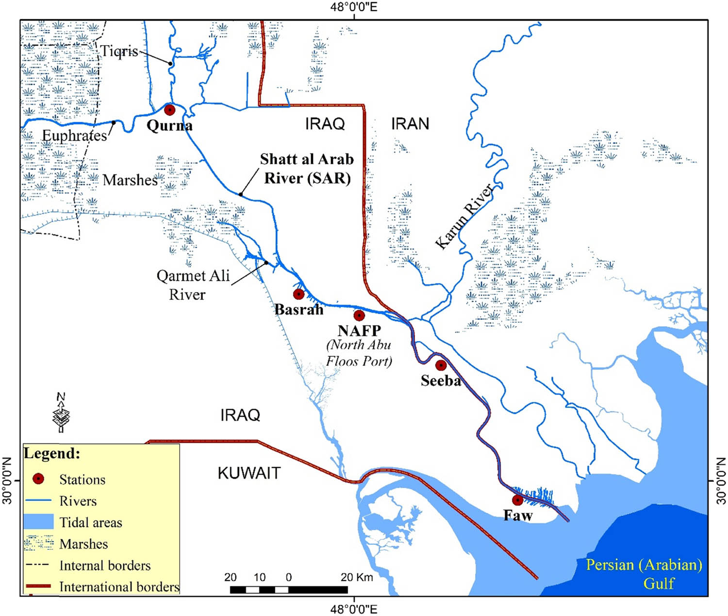
SAR site, 48°1′57.25″E and 30°27′28.67″N (mapped by authors).
2.1 Salt front
The water of the SAR suffers from severe salinity as a result of the presence of chloride (CL) salts recorded (2,893–26,127 mg/L). The percentage, which exceeds 50% of the salts in the SAR water (SO4), comes from the Gulf water and their concentrations are being higher toward the mouth of the river, and it is called the salt front. The lack of freshwater imports in the Tigris and Euphrates rivers, as a result of the construction of many dams in the source countries, and has affected the incoming discharges to the SAR. They were 1,189 m3/s in September 1991, while these discharges decreased to less than 20 m3/s in August 2018. This decrease led to an increase in the total concentrations of dissolved solid salts (TDS) and salinity to very large levels. The TDS values were recorded between 6,693 and 51,860 mg/L in different locations of SAR, and the total hardness (TH) values were 1,267–8,064 mg/L [10]. Figure 2 presents the salinity in form of TDS, CL, TH, and sulfur salts (SO4) for five different locations in SAR. This phenomenon negatively affected the biological diversity in the area and led to the disturbance of the natural ecosystems and deterioration of the quality of the freshwater.
![Figure 2
TDS, CL, TH, and sulfur salts (SO4) of the water of the SAR for different locations recorded in August 2018 [10].](/document/doi/10.1515/jmbm-2022-0201/asset/graphic/j_jmbm-2022-0201_fig_002.jpg)
TDS, CL, TH, and sulfur salts (SO4) of the water of the SAR for different locations recorded in August 2018 [10].
The HEC-RAS (Hydrologic Engineering Center-River Analysis System) program was employed to study the salt front effect in SAR. The different simulation models showed at the low incoming flow, less than 20 m3/s in SAR, and the salt front has an effect starting from the NAFP location, where its effects (salt front) can be prevented by increasing the incoming freshwater discharges in SAR by more than 50 m3/s, as shown in Figure 3. However, the current water policy of the upstream countries imposes restrictions on the volume of water releases, and increased discharges have become difficult according to the current conditions and need other solutions to prevent the freshwater deterioration of the Shatt Al-Arab River. Among the proposed solution is a construction of a hydraulic structure regulator, such as weir, barrage, or rubber dam, to control the salt front at the time of the sea tide.
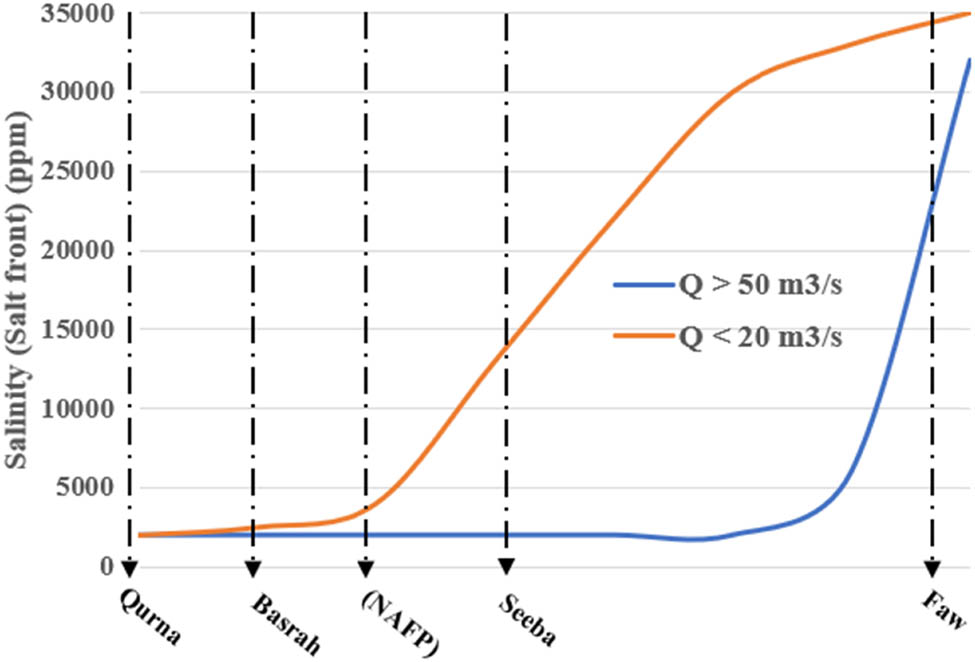
Effect of the salt front from the Arabian/Persian Gulf with incoming discharge in SAR (delineated by authors based on the literature).
Choosing the suitable hydraulic structure regulator and its location to control the Shatt Al-Arab River problem requires studying the hydraulic characteristics, geotechnical considerations, and sediments profiles of SAR.
2.2 Hydraulic characterization
Table 1 presents the hydraulic properties of SAR at five sites, including Qurna and Basra city representing near upstream, and downstream of NAFP, Seeba, and Faw, respectively [11]. Figure 4 shows the various water depths in SAR for different locations starting from Qurna and ending at Faw.
SAR hydraulic property parameters (MSC 2018)
| Hydraulic properties | Qurna | Basrah | NAFP | Seeba | Faw |
|---|---|---|---|---|---|
| Width (m) | 202 | 370 | 400 | 404 | 650 |
| Depth (m) | 5.7 | 10 | 6 | 11.8 | 10 |
| Max velocity (m/s) | 0.6 | 0.5 | 0.5 | 0.61 | 0.95 |
| High water level (m) | 0.15 | 1.8 | 0.45 | 1.30 | 2.1 |
| Low water level (m) | 0.1 | 0.6 | −0.40 | −0.25 | −0.7 |
| Average tidal range (m) | 0.25 | 1.2 | 0.85 | 1.55 | 2.80 |
| Measured ebb discharge (m3/s) | 104 | 835 | — | 344 | 820 |
| Measured flood discharge (m3/s) | 99 | 690 | — | 258 | 635 |
| Area (m2) | 873 | 3300 | 4347 | 2958 | 3779 |
| Hydraulic radius (m) | 7.36 | 5.12 | — | 5.02 | |
| Roughness of the bed | 0.025 | 0.037 | 0.035 | 0.026 | 0.017 |
| Conveyance (m3/s) | — | 25694 | — | — | |
| Wet perimeter (m) | 476 | 607 | 363 | 761 | |
| d 90 (mm) | 0.0016 | 0.0014 | 0.0034 | — | 0.0035 |
| d 50 (mm) | 0.025 | 0.016 | — | 0.027 | |
| Mean sea level (m) | — | 1.92 | — | — | 1.70 |
![Figure 4
SAR water depth profile, modified after [11].](/document/doi/10.1515/jmbm-2022-0201/asset/graphic/j_jmbm-2022-0201_fig_004.jpg)
SAR water depth profile, modified after [11].
2.3 Geotechnical consideration
The soil layers are mainly composed of soft clay and silt to the depth of 20 m. After this depth, the stiffness of the layers increases and reaches the highest standard penetration test values (>50) at 23 m of depth and greater (Figure 5). This deep layer presents hard and/or very dense sandy layers that are necessary, as a high bearing capacity layer, for deep foundations of the high load constructions.
![Figure 5
SAR soil profile, modified after [24].](/document/doi/10.1515/jmbm-2022-0201/asset/graphic/j_jmbm-2022-0201_fig_005.jpg)
SAR soil profile, modified after [24].
2.4 Sediment profiles
SAR sediment profile is a part of the Tigris–Euphrates river sedimentary system. Most sediments of the system are fine-grained (mud). The large discharges of SAR in the past carry huge sediment loads deposited mostly at the mouth of the river. It is worth noting that there has been a remarkable contribution of the freshwater and sediment loads coming from the Iranian Karun river meeting SAR at a distance of 127 km (Figure 1). Karun river significantly increases the sediment loads deposited in the southern part and mouth of SAR yet positively impacts the SAR freshwater. The riverbed sediments are mostly fine-grained (mud) sediments and become finer as heading toward the mouth of the river. This is ascribed to the widening of the channel cross section to the south and the low longitudinal slope of the river channel (1 cm/km) as well. Slowing down the velocity of the river currents stimulates the fines (mud) to deposit. Contents of the clay, silt, and sand range between 40–48, 50–59, and 0.4 and 1.0, respectively, at the Abu Flous port location [12,13] (Table 2).
Sediment types for selected sites on SAR
| Site | Sand (%) | Silt (%) | Clay (%) | Sediment class |
|---|---|---|---|---|
| Qurna | 4–8 | 50–62 | 30–38 | Clayey Silt with few sand |
| Basrah | 2–11 | 43–55 | 40–34 | Clay-Silt with few sand |
| NAFP | 0.4–1.0 | 59–50 | 41–48 | Clayey Silt |
| Seeba | 2–10 | 43–50 | 35–45 | Clayey Silt |
| Faw | 5–10 | 70–75 | 20–25 | Clayey Silt with few sand |
It is evident that NAFP location will be a suitable selected location for constructing the hydraulic structure regulator in SAR to control the tidal effects and prevent the salt front.
3 Hydraulic structure regulators
The proposed hydraulic structure regulators must conserve freshwater on the upstream side and avoid interfering with the inflow of the saline tidal water. Several studies presented the advantage and disadvantages of using weirs, barrages, and rubber dams as regulators in the tide river [14,15,16,17,18,19,20,21,22,23]. Table 3 summarizes the comparison between three proposed hydraulic structures regulators (weir, barrage, and inflatable rubber dam) tested in SAR. The comparison showed that the barrage and the inflatable rubber dam are feasible choices. Since the salt front only affects the river water during flood conditions, there is no effect during the ebb conditions. The inflatable rubber dam will be more feasible than the barrage structure; furthermore, the NAFP site, which has a total water depth of less than 8 m, will be a suitable location for the inflatable rubber dam.
Proposed hydraulic structure regulator comparison
| Regulator type | Control | ||||
|---|---|---|---|---|---|
| Salt front | Groundwater level (U/S) | Sediment accumulated | Traffic river navigation | River water depth with a height ≥8 m | |
| Weir | Efficient | Not efficient | Not efficient | Not efficient | Not efficient |
| Barrage | Efficient | Efficient | Restricted efficient | Efficient | Efficient |
| Rubber dam | Efficient | Efficient | Efficient | Efficient | Not efficient |
3.1 Inflatable rubber dam
The traditional inflatable rubber dam consists of a rubber air bladder made from ethylene propylene diene monomer rubber, which can be both inflated and deflated as required. A concrete leveling pad is required to install the rubber dam to the river bed and ensure that the dam has the appropriate structural capacity to resist hydrostatic pressures. The inflatable rubber dam is vulnerable to damage and punctured due to sharp objects carried by river water, which is one of the major disadvantages. However, using the inflatable rubber dam with a metal gate substantially provides high protection from vandalism and increases the integrity of the rubber dam installation compared to the traditional rubber dam. The metal gate consists of a series of metal sheets connected together through watertight inter panel seals that install longitudinally along the rubber dam width. The gates are raised using the rubber air bladder inflated to reach the required dam height specified for the project. The rubber dam with a metal gate provides approximately 30% greater discharge compared to the traditional rubber dam. The inflatable rubber dam with a metal gate in the NAFP site, a tidal environment not far from the sea, and separates downstream saline water as it impounds upstream freshwater flow in the SAR. The main mechanism of using the rubber dam in the tidal river is to conserve freshwater on the upstream side and prevent the inflow of the saline tidal water from the downstream.
3.1.1 Proposed design
The suitable hydraulic property parameters for the selected regulator location must not affect the river navigation traffic in SAR. It was determined that six 8 m-high by 67 m-wide inflatable rubber dam with metal gates a total length of 402 m spaced about 1,600 m apart from the upstream Abo Flous port would provide the most economical and best technical solution, as shown in Figure 6.

Proposed inflatable rubber dam with a metal gate in SAR-NAFP location (plotted by authors using Google Earth Image).
The proposed design of inflatable rubber dams with a metal gate (Figure 7) was checked and proved by one of the biggest and pioneer companies in the design and supply the inflatable rubber dams, namely, the Obermeyer hydro company (http://www.obermeyerhydro.com) and its partner Dyrhoff Company (http://www.dyrhoff.co.uk). The company has rechecked the suitability of the proposed design parameters for the dams to comply with the hydraulic characteristics parameters of the Shatt Al-Arab River at the NAFP location as depicted in Figure 6. The concrete footing for the rubber dam with the gate can be recessed to allow the full extent of the gate to be placed below the channel bottom when deflated. This promotes an undisturbed flow regime over the top of the dam location during a severe storm event when the dams are subsequently deflated. Table 4 introduces the design parameters for an inflatable rubber dam with a metal gate in the NAFP location.

Proved design of the proposed inflatable rubber dam with a metal gate in SAR.
Inflatable rubber dam with metal gate design parameters
| Parameters | Value |
|---|---|
| Length of rubber bag (m) | 67 |
| Height of the rubber bag (m) | 6 |
| Thickness of rubber bag (mm) | 8 |
| Lifetime of the bag (years) | 30–40 |
| Duration of air filling in the bag (min) | 40–50 |
| Rubber dam coefficient (provided by Obermeyer Hydro, Inc.) | 3.3 |
| Pump capacity (m3/s) | 120 |
| Metal gate height (m) | 8 |
4 Conclusion
The inflatable rubber dam was investigated in this study to reduce the salt front from the Arabian/Persian Gulf. The study concluded that:
Using an inflatable rubber dam with a metal gate to prevent the vandalism against sharp objects carried out by river water.
According to SAR problem conditions, the employed inflatable rubber dam to control the salt front is more economical and efficient than other hydraulic structures.
Based on the manufacturing product limitations, the inflatable rubber dam technology is feasible in small and medium rivers with a water depth less than 8 m. Otherwise, using other technologies will be more economical.
The rubber dam with a metal gate provides approximately 30% greater discharge compared to the traditional rubber dam.
The NAFP location will be a suitable location for constructing the hydraulic structure regulators.
-
Funding information: No funding involved.
-
Author contributions: All authors accepted responsibility for the entire content of this manuscript and approved its submission.
-
Conflict of interest: No conflict of interest.
References
[1] Tam PWM. Use of rubber dams for flood mitigation in Hong Kong. J Irrig Drain Eng. 1997;123(2):73–8.10.1061/(ASCE)0733-9437(1997)123:2(73)Search in Google Scholar
[2] Novak P. Hydraulic structures. J Hydraulic Res. 2008;46:715.10.4324/9781482267754Search in Google Scholar
[3] Chanson H. Use of rubber dams for flood mitigation in Hong Kong – Discussion. J Irrig Drain Eng-Asce. 1997;124:181–2.10.1061/(ASCE)0733-9437(1998)124:3(181)Search in Google Scholar
[4] Tam PWM, Zhang XQ. Management of rubber dams in Hong Kong. Can J Civ Eng. 1999;26(2):123–34.10.1139/l98-037Search in Google Scholar
[5] Zhang XQ, Tam PWM, Zheng W. Construction, operation, and maintenance of rubber dams. Can J Civ Eng. 2002;29(3):409–20.10.1139/l02-016Search in Google Scholar
[6] Hasan S, Kabir I. Feasibility of natore rubber dam on Mahanonda river in Bangladesh and its performance on irrigation. Am J Eng Res. 2014;03(01):27–34.Search in Google Scholar
[7] Parish Y. Evaluating the design, construction and use of rubber dams. Int J Adv Biotechnol Res. 2016;7(1):976–2612. http://www.bipublication.com.Search in Google Scholar
[8] Hamdan ANA, Abbas AA, Najm AT. Flood hazard analysis of proposed regulator on Shatt Al-Arab River. Hydrology. 2019;6(3):80.10.3390/hydrology6030080Search in Google Scholar
[9] Al-Badran BN. Delta of river Shatt Al Arab south Iraq. Mar Mesopotamica. 2004;19(2):311–22.Search in Google Scholar
[10] Hamdan ANA, Al-Mahdi AAJ, Mahmood AB. Modeling the effect of sea water intrusion into Shatt Al-Arab River (Iraq). J Univ Babylon Eng Sci. 2020;28(28):210–24.Search in Google Scholar
[11] MSC, Marine Science Center. Environmental impact Study of Dams proposed on Shatt al Arab River, southern Iraq. Internal Report; 2018.Search in Google Scholar
[12] Al-Mulla S. Geomorphological study of the Shatt al Arab Basin using remote sensing techniques [dissertation]. Basra: Fine College, the University of Basrah; 2005.Search in Google Scholar
[13] Muttashar WR, Bryson LS, Al-Humaidan ZA. The use of particle size distribution integrated with consistency limits for experimentally simulating fine-grained sedimentary units. Arab J Geosci. 2021;14:2436. 10.1007/s12517-021-08812-7.Search in Google Scholar
[14] Tam PWM. Application of inflatable dam technology–problems and countermeasures. Can J Civ Eng. Apr 1998;25(2):383–8.10.1139/l97-090Search in Google Scholar
[15] Indian Standard. Hydraulic design of Barrages and Weirs, Guidelines. New Delhi: Bureau of Indian Standards; 1989.Search in Google Scholar
[16] Maatooq J, Alwash H, Al-Khafaji H. Analysis seepage and uplift pressure for Al-Shamiya Barrage south of Iraq. Eng Tech J. 2015 December;33:838–44.10.30684/etj.33.4A.7Search in Google Scholar
[17] AlKhafaji H, Imani M, Fahimifar A. Three-dimensional bearing capacity analysis of rock foundations subjected to complicated loadings, case study: Shafaroud dam. AUT J Civ Eng. 2020;5:257–68. https://ajce.aut.ac.ir/article_3965.html%0Ahttps://ajce.aut.ac.ir/article_3965_2569add08fabb6bf6690762217ce6f1b.pdf.Search in Google Scholar
[18] Alkhafaji H, Imani M, Fahimifar A. Determining the stress-settlement distribution of a gravity dam foundation considering different water levels using finite element method. Lect Notes Civ Eng. 2021;112:217–27.10.1007/978-981-15-9399-4_19Search in Google Scholar
[19] Karkush MO, Sabaa MR, Salman AD, Al-Rumaithi A. Prediction of bearing capacity of driven piles for Basrah governatore using SPT and MATLAB. J Mech Behav Mater. 2022 Jan 1;31(1):39–51.10.1515/jmbm-2022-0005Search in Google Scholar
[20] Karkush MO, Ahmed MD, Sheikha AA, Al-Rumaithi A. Thematic maps for the variation of bearing capacity of soil using SPTs and MATLAB. Geosciences. 2020 Sep;10(9):329.10.3390/geosciences10090329Search in Google Scholar
[21] Hekmatzadeh AA, Zarei F, Johari A, Torabi, Haghighi A. Reliability analysis of stability against piping and sliding in diversion dams, considering four cutoff wall configurations. Comput Geotech. 2018;98:217–31.10.1016/j.compgeo.2018.02.019Search in Google Scholar
[22] Alkhafaji H, Meysam I. Numerical simulation of driven piles under static axial compressive load testing using finite element model. In: Karkush MO, Choudhury D, editors. Geotechnical Engineering and Sustainable Construction. Singapore: Springer; 2021. p. 305–31. 10.1007/978-981-16-6277-5_24.Search in Google Scholar
[23] Johari A, Heydari A. Reliability analysis of seepage using an applicable procedure based on stochastic scaled boundary finite element method. Eng Anal Bound Elem. 2018;94:44–59. 10.1016/j.enganabound.2018.05.015.Search in Google Scholar
[24] Al-Badran BN, Mahmood RA. Geotechnical properties and aerial distribution of bearing strata along the Shatt Al-Arab Riverbank from Qurna to Faw. Mesopotamian J Mar Sci. 2006;21(1):45–56.Search in Google Scholar
© 2023 the author(s), published by De Gruyter
This work is licensed under the Creative Commons Attribution 4.0 International License.
Articles in the same Issue
- Research Articles
- The mechanical properties of lightweight (volcanic pumice) concrete containing fibers with exposure to high temperatures
- Experimental investigation on the influence of partially stabilised nano-ZrO2 on the properties of prepared clay-based refractory mortar
- Investigation of cycloaliphatic amine-cured bisphenol-A epoxy resin under quenching treatment and the effect on its carbon fiber composite lamination strength
- Influence on compressive and tensile strength properties of fiber-reinforced concrete using polypropylene, jute, and coir fiber
- Estimation of uniaxial compressive and indirect tensile strengths of intact rock from Schmidt hammer rebound number
- Effect of calcined diatomaceous earth, polypropylene fiber, and glass fiber on the mechanical properties of ultra-high-performance fiber-reinforced concrete
- Analysis of the tensile and bending strengths of the joints of “Gigantochloa apus” bamboo composite laminated boards with epoxy resin matrix
- Performance analysis of subgrade in asphaltic rail track design and Indonesia’s existing ballasted track
- Utilization of hybrid fibers in different types of concrete and their activity
- Validated three-dimensional finite element modeling for static behavior of RC tapered columns
- Mechanical properties and durability of ultra-high-performance concrete with calcined diatomaceous earth as cement replacement
- Characterization of rutting resistance of warm-modified asphalt mixtures tested in a dynamic shear rheometer
- Microstructural characteristics and mechanical properties of rotary friction-welded dissimilar AISI 431 steel/AISI 1018 steel joints
- Wear performance analysis of B4C and graphene particles reinforced Al–Cu alloy based composites using Taguchi method
- Connective and magnetic effects in a curved wavy channel with nanoparticles under different waveforms
- Development of AHP-embedded Deng’s hybrid MCDM model in micro-EDM using carbon-coated electrode
- Characterization of wear and fatigue behavior of aluminum piston alloy using alumina nanoparticles
- Evaluation of mechanical properties of fiber-reinforced syntactic foam thermoset composites: A robust artificial intelligence modeling approach for improved accuracy with little datasets
- Assessment of the beam configuration effects on designed beam–column connection structures using FE methodology based on experimental benchmarking
- Influence of graphene coating in electrical discharge machining with an aluminum electrode
- A novel fiberglass-reinforced polyurethane elastomer as the core sandwich material of the ship–plate system
- Seismic monitoring of strength in stabilized foundations by P-wave reflection and downhole geophysical logging for drill borehole core
- Blood flow analysis in narrow channel with activation energy and nonlinear thermal radiation
- Investigation of machining characterization of solar material on WEDM process through response surface methodology
- High-temperature oxidation and hot corrosion behavior of the Inconel 738LC coating with and without Al2O3-CNTs
- Influence of flexoelectric effect on the bending rigidity of a Timoshenko graphene-reinforced nanorod
- An analysis of longitudinal residual stresses in EN AW-5083 alloy strips as a function of cold-rolling process parameters
- Assessment of the OTEC cold water pipe design under bending loading: A benchmarking and parametric study using finite element approach
- A theoretical study of mechanical source in a hygrothermoelastic medium with an overlying non-viscous fluid
- An atomistic study on the strain rate and temperature dependences of the plastic deformation Cu–Au core–shell nanowires: On the role of dislocations
- Effect of lightweight expanded clay aggregate as partial replacement of coarse aggregate on the mechanical properties of fire-exposed concrete
- Utilization of nanoparticles and waste materials in cement mortars
- Investigation of the ability of steel plate shear walls against designed cyclic loadings: Benchmarking and parametric study
- Effect of truck and train loading on permanent deformation and fatigue cracking behavior of asphalt concrete in flexible pavement highway and asphaltic overlayment track
- The impact of zirconia nanoparticles on the mechanical characteristics of 7075 aluminum alloy
- Investigation of the performance of integrated intelligent models to predict the roughness of Ti6Al4V end-milled surface with uncoated cutting tool
- Low-temperature relaxation of various samarium phosphate glasses
- Disposal of demolished waste as partial fine aggregate replacement in roller-compacted concrete
- Review Articles
- Assessment of eggshell-based material as a green-composite filler: Project milestones and future potential as an engineering material
- Effect of post-processing treatments on mechanical performance of cold spray coating – an overview
- Internal curing of ultra-high-performance concrete: A comprehensive overview
- Special Issue: Sustainability and Development in Civil Engineering - Part II
- Behavior of circular skirted footing on gypseous soil subjected to water infiltration
- Numerical analysis of slopes treated by nano-materials
- Soil–water characteristic curve of unsaturated collapsible soils
- A new sand raining technique to reconstitute large sand specimens
- Groundwater flow modeling and hydraulic assessment of Al-Ruhbah region, Iraq
- Proposing an inflatable rubber dam on the Tidal Shatt Al-Arab River, Southern Iraq
- Sustainable high-strength lightweight concrete with pumice stone and sugar molasses
- Transient response and performance of prestressed concrete deep T-beams with large web openings under impact loading
- Shear transfer strength estimation of concrete elements using generalized artificial neural network models
- Simulation and assessment of water supply network for specified districts at Najaf Governorate
- Comparison between cement and chemically improved sandy soil by column models using low-pressure injection laboratory setup
- Alteration of physicochemical properties of tap water passing through different intensities of magnetic field
- Numerical analysis of reinforced concrete beams subjected to impact loads
- The peristaltic flow for Carreau fluid through an elastic channel
- Efficiency of CFRP torsional strengthening technique for L-shaped spandrel reinforced concrete beams
- Numerical modeling of connected piled raft foundation under seismic loading in layered soils
- Predicting the performance of retaining structure under seismic loads by PLAXIS software
- Effect of surcharge load location on the behavior of cantilever retaining wall
- Shear strength behavior of organic soils treated with fly ash and fly ash-based geopolymer
- Dynamic response of a two-story steel structure subjected to earthquake excitation by using deterministic and nondeterministic approaches
- Nonlinear-finite-element analysis of reactive powder concrete columns subjected to eccentric compressive load
- An experimental study of the effect of lateral static load on cyclic response of pile group in sandy soil