Electrochemical Advanced Oxidation Processes (EAOP) to degrade per- and polyfluoroalkyl substances (PFASs)
-
C Fang
 ,
M Megharaj
,
M Megharaj

Abstract
Per- and polyfluoroalkyl substances (PFASs) have been recently listed as emerging contaminants (ECs) and persistent organic pollutants (POPs) due to their human and environmental health concerns. In the last 10 years, their detection and remediation have progressed significantly. Herein, we critically review recent developments in electrochemical advanced oxidation process (EAOP) towards their remediation. Particular attentions are paid to perfluorooctane sulfonate (PFOS) and perfluorooctanoic acid (PFOA), which present the main concerns of PFASs at this time. Due to the persistence of those PFASs, other remediation approaches may experience difficulty in degrading them, whilst EAOP has demonstrated success. The fundamentals of EAOP are highlighted and the scale-up application is discussed regarding the future research directions.
1 Introduction
1.1 PFASs
Emerging contaminants (ECs) are chemicals, substances or materials showing emerging threat to human and / or environmental health [1, 2]. The contaminants could have existed in the environment for a long period of time but recent research has shown proof of their potential adverse effects. Examples of such ECs are per- and polyfluoroalkyl substances (PFASs) (or perfluorinated compounds, PFCs) [3]. Alternatively, the contaminants have just recently appeared in the environment (emerging compounds), such as nanomaterials [4, 5].
PFASs feature unique physical and chemical properties, such as hydrophobicity and oleophobicity, which have not being evidenced in other compounds. Therefore, they have been widely used in such applications as clothing, upholstery, carpeting, painting, food containers, cookware, aqueous film-forming foams (AFFFs) etc. [3, 6–8] On the other hands, PFASs also exhibit extreme stability with respect to thermal, chemical and biodegradation so that those compounds are also generally categorised as persistent organic pollutants (POPs) [9, 10]. That is, their inert fluoro-carbon skeletons are resistant to degradation under natural environmental conditions [11, 12]. Consequently, their usage and inertness have led to their global distribution and accumulation in the environment. This has in turn raised serious concerns about their impact on the environment and public health [13–15].
Once PFASs contamination is identified and monitored [16–19], the scientific community typically responds by developing remediation strategies. For example, electrochemical remediation has been well advanced towards the remediation of PFASs [20, 21]. The increasing attention can be evidenced in Figure 1whilst Table 1lists the typical PFASs discussed in this review.
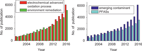
Number of yearly published scientific articles. The data were collected via ScienceDirect Website (http://www.sciencedirect.com/) using the following typical words: “electrochemical advanced oxidation process”, “environment remediation”, “emerging contaminant” and “PFASs”, respectively.
PFASs discussed in this review.
| Acronym | Molecular structure | Name | ACS number | Main usage |
|---|---|---|---|---|
| PFOS | CF3(CF2)7SO3H | perfluorooctane sulfonate | 1763-23-1 | surfactant in AFFFs (previously), stain, repellents, etc. |
| PFBS | CF3(CF2)3SO3H | perfluorobutanoic sulfonate | 375-73-5 | Ingredient or by-product of longer chain’s degradation |
| PFOA, C8 | CF3(CF2)6CO2H | perfluorooctanoic acid | 335-67-1 | surfactant in emulsion polymerisation of fluoropolymers, AFFFs (previously), etc. |
| PFHpA, C7 | CF3(CF2)5CO2H | perfluoroheptanoic acid | 375-85-9 | Ingredient or by-product of longer chain’s degradation |
| PFHxA, C6 | CF3(CF2)4CO2H | perfluorohexanoic acid | 307-24-4 | Ingredient or by-product of longer chain’s degradation |
| PFPeA, C5 | CF3(CF2)3CO2H | perfluoropentanoic acid | 2706-90-3 | Ingredient or by-product of longer chain’s degradation |
| PFBA, C4 | CF3(CF2)2CO2H | perfluorobutanoic acid | 375-22-4 | Ingredient or by-product of longer chain’s degradation |
1.2 PFASs’ degradation: Current approaches
Numerous remediation approaches currently exist, including adsorption, stabilisation, filtration, coagulation, separation, chemical oxidation / reduction, thermal decomposition, UV / photo-catalytic degradation, etc. [22] All these remediation approaches can be generally categorised into two types, removal (such as adsorption) and degradation (mineralisation). The latter demonstrates its advantage as a clean-up approach because the remediation products will be CO2, water and other inorganic ions or molecules. However, for POPs’ degradation, the available approach is currently limited in its effectiveness. Taking PFOS / PFOA (Table 1) as an example, its degradation at industrial scale is currently only being achieved with high temperature combustion (>1100 °C) [12]. Other approaches have delivered only limited success, mostly in laboratories and the research is still ongoing.
1.3 AOP /EAOP
Advanced oxidation process (AOP) has received world-wide attention in last decades [23]. It uses radicals, typically hydroxyl radicals (●OH), to attack the POPs and degrade them into fragments or inorganic ions / molecules [24]. The AOP generally employs ozone (O3), hydrogen peroxide (H2O2) or UV light with help of catalysis to produce the radical of ●OH, one of the most aggressive oxidants. The produced radicals usually behave short life-time, such as 2–4 µs in aqueous media for ●HO [25]. Therefore, the possible contamination from the residual reactants is thus effectively declined. Consequently, it has received increasing attention for the treatment of waste water [26].
However, the AOP requires chemicals or others (such as UV, catalysis) to generate radicals, which usually means harsh conditions and a low environmental compatibility. Electrochemical advanced oxidation process (EAOP) overcomes some of these limitations because the radicals can be generated in-situ via electrochemistry, which means the oxidation process can be driven by electricity rather than by chemicals to produce radicals. The less consumption on chemicals of EAOP promises a more environment-friendly approach [27].
Furthermore, the electrochemical process can directly oxidise the to-be-degraded targets or generate other radicals beyond ●OH, such as ●O2−(superoxide radical), ●HO2 (hydroperoxyl radical), etc., which can potentially break down some POPs that cannot be broken down by ●HO alone. This is true in the case of the remediation of PFASs [12]. The fluoro-carbon skeletons is so stable that it can resist the attack of ●HO [28]. However, the EAOP has been proven to be an effective method for breaking down PFASs.
Apart from its high efficiency and powerful degradation capacity, other advantages include environmental compatibility (using electricity rather than chemicals), versatility, and universal degradation capability, etc. [20, 24, 29] Consequently, EAOP has drawn increasing attention, which can be evidenced by the number of publications shown in Figure 1, and witnessed by recently published reviews [20, 23, 24, 26, 30–34].
Herein, we will discuss the principles of EAOP, then its application for the remediation of PFASs. In the conclusion section we will highlight the challenges and recommend possible directions for future research.
2 Principle of EAOP
2.1 pH-potential diagram
In an EAOP cell, to generate the radical of ●HO, the electrode must be polarised, as shown in Figure 2(a). Note the exact potential of the radical’s redox depends on the measurement environment, which varies in the literatures [20, 35–37].
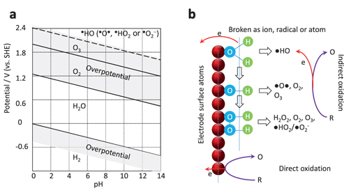
pH-potential diagram (a) and the schematic illustration of the anode reaction (b). In (a), the shadows mark the overpotential areas. The possible initial oxidation products and further products (bracketed) are suggested. In (b), water is electrolysed to generate radical of ●HO or adsorbed–OH group, which can be further oxidised as ●O●, or recombined as H2O2 (adsorbed), O2, O3 after further breaking the O-H bonds, from top to bottom. The process of indirect oxidation of target (R) to (O) with the involvement of radicals is shown on the top whilst the direct oxidation is shown on the bottom.
Most of the radicals are not as stable as the molecules of O2 or O3 (life-time of 2–4 µs in aqueous media for ●HO [25]). Their zone is thus marked with dashed line in Figure 2(a). In the meantime, overpotential is marked as shadow areas, which depends on the electrode materials [38].
In an effort to improve the degradation efficiency of EAOP, we hope to boost the productivity of radicals whilst suppressing the emission of O2 and O3. For this reason we must select the electrode materials so that their overpotential of O2 and O3 is high, such as boron-doped diamond, lead peroxide, which will be discussed in the following section.
2.2 Radicals and degradation reactions
The generation process of the radical is complicated [33]. In Figure 2(b) (top), we can see the simplified model of a water molecule that is adsorbed on the electrode surface [30, 36, 39]. In general, the oxidised products include ●HO, ●O−, ●HO2, ●O2−, H2O2, O2, O3. In principle, they have higher energy than that of H2O, enabling them to act as oxidants to degrade organic molecules.
On the other hand, if there are other ions or moieties in the solution, the products might be more complicated. For example, the presence of Cl- can generate Cl2, HClO, HClO2, HClO3, HClO4 [35] and the corresponding radicals [40], SO42− can generate S2O82− and radicals as well [34]. In some cases, the EAOP can be enhanced, such as S2O82− as a strong oxidant and Fe2+/3+ as a media that activates Fenton reaction [41]. In other cases, some by-products might bring about the secondary contamination, such as ClO4− (an EC itself). Hence, those parameters should be considered and optimised for subsequent improvement and development [34, 36].
Furthermore, the degradation reaction is predominantly a sequence of chain reactions, which involve initial and subsequent steps [24]. Taking PFOA as an example, the total reaction can be written as below,
According to Marcus [42], each subsequent step involves at most one electron exchange. Therefore, the initial step must be followed by a series of gentle subsequent steps, to completely mineralise PFOA to CO2, HF and H+ with the involvement of 14 electrons. The HF appearance and the pH modification might affect the production of radicals and the mineralisation process, which is not well-known yet. This complicates the degradation mechanism and will be further discussed in the following.
2.3 Electrode materials
As stated previously, to boost the productivity of radicals and inhibit the emission of O2, the electrode materials reported in literatures include platinum (Pt) [43], carbon or graphite (C) [44, 45], iridium dioxide (IrO2) [46], ruthenium dioxide (RuO2) [47], tin dioxide (SnO2) [48], boron-doped diamond (BDD) [49], lead dioxide (PbO2) [32], Ti4O7 (Ebonex) [39], TiO2 nanotube array [34] as well [24, 36]. Among them, BDD has been reported to be the best for water treatment [49].
On the other hand, it is well-known that the initial oxidation of Pt surface (and other noble metals) can catalyse (direct) oxidation of some organics in a lower potential window than that of the emission of O2 and the radical generation [50]. However, this process is slow and depends strongly on the electrocatalytic activity of the electrode, which hampers its application for remediation. Consequently, this aspect will not be discussed further here [31].
2.4 Cell
The EAOP is driven by the current flow. To maximise electrical efficiency, the main voltage loss should occur on the electrode surface, rather than on the solution part (or the external circuit). Therefore, a supporting electrolyte is added intentionally to increase the conductivity of the water sample. The common electrolyte is sodium sulphate (Na2SO4) due to its stability. Other supporting electrolytes such as sodium perchlorate (NaClO4) have also been reported, but perchlorate itself is an EC. Some ions should be of concern, such as Cl- which might poison the electrode surface and be oxidised to an EC of ClO4− [35].
The cell design usually requires two electrodes in parallel with an inter-distance of <1 cm, as presented in Figure 3(a) [48]. The cell can consist of an electrode array, as shown in Figure 3(b), which features an improved degradation efficiency [31]. On the other hand, the cathode can be replaced with cheap materials (c, d), such as a carbon electrode (graphite), even metal ones (cast iron, stainless steel, copper) or air-diffusion electrodes to boost the production of H2O2 [30, 41]. The configuration might also behave as a flow-through cell (cylinder or porous panels) (d, e) to increase the transportation efficiency [33, 36]. In Figure 3(d, e), in order to enhance the degradation efficiency, the space between the anode and cathode can be filled with nanomaterials (such as functionalised activated carbon) or an additional electrode couple [34, 51].
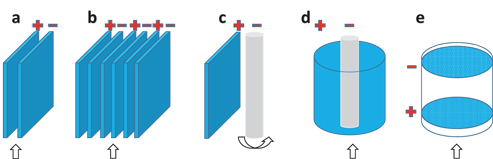
Configurations of the EAOP cells. (a) the same anode and cathode materials in parallel with a gap of <1 cm; (b) electrode array; (c) cathode is replaced with carbon, metal, or air-diffusion electrode; (d) and (e) flow through cells whilst the space between the anode and cathode can be filled with additional electrodes / gradual activated carbon. The stirring / flowing direction is indicated.
3 Degradation of PFASs
The bonds’ (among PFASs) energies are shown in Figure 4(a), with other related compounds as references [12, 52, 53]. Considering the bond strength / energy, the degradation of PFASs is most likely to happen via a cleavage of the C–C chain rather than the C–F bond, particularly the CF2–COOH bond in PFOA and the CF2–SO3H bond in PFOS. In other words, defluorination is more difficult to achieve than the degradation of the C–C chain via oxidation, unless catalysis is carried out to target on the C–F bond.
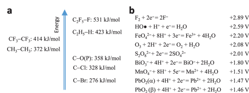
Schematic drawing of the energy level of the covalent bonds (a) and standard redox potentials of selected ones (b). Note the values varies in the literatures.
In parallel, chlorinated organics are not as stable as PFASs. The bond energy of C-Cl is 328 kJ/mol whilst C-F is 531 kJ/mol, as shown in Figure 4(a), which means they can be directly degraded by the radical of ●HO. Also, because the bond energy of C-C (372 kJ/mol) is higher than that of C-Cl (328 kJ/mol), the dechlorination is thus easier than to break the C-C bond. In most cases, dechlorination can be achieved by either oxidation on an anode surface [54] or reduction on a cathode surface [55], which is obviously different from that of the PFASs’ breakdown. Therefore, EAOP might lose its advantage over AOP to some degree with reference to the remediation of chlorinated substances. We will focus on PFASs degradation in this review.
As said, there are various degradation approaches [12], for example Fenton reaction of hydrogen peroxide [28], persulphate [12], chemical oxidation [56], sonolytic conversion [57], etc. This review focuses on EAOP [58] that is summarised in Table 2. The reason for selecting EAOP is shown in Figure 4(b), where the radical of ●HO indicates the second highest redox potential, suggesting a strong oxidation capacity [38, 59]. This oxidation capacity will be enhanced in the EAOP cell where the oxidant of ●HO can be in-situ generated and refreshed, as discussed previously.
Degradation of PFASs via EAOP.
| PFASs | Initial concentration | Degradation efficiency | Kinetics | Degradation amount | Electrode materials/gap | Electrolyte | Current density/efficiency | Time duration | Ref. | Comments |
|---|---|---|---|---|---|---|---|---|---|---|
| PFOS | 0.4 mM | ~80% | Zeroth order, 0.0123 mM/h, kicking off at 2.7 V (vs. SHE) | 2L | BDD—-BDD /3 mm | 10 mM NaClO4 | 20 mA/cm2 /20-100 % | ~30 min | [11] | Exper + simulation |
| PFBS/C4 | 0.4 mM | >97 % | Zeroth order, 0.004 mM/h kicking off at 3.0 V (vs. SHE) | 1 L | BDD----BDD /3 mm | 10 mM NaClO4 | 10 mA/cm2/3.3−4.4 % | 120 min | [60] | Exper + simulation |
| PFOA | 0.12 mM /50 ppm | >99 % | First-order, kPFOA = 1.93 h−1, kicking off at 3.61 V (vs. SHE) | 0.025 L | Ti/SnO2-Sb-Bi----Ti /1 cm | 11.4 mM NaClO4 | ~20 mA/cm2/nil | 120 min | [58] | ESI confirmed the PFAS radical |
| PFOA, PFOS + | 0.114 mM | 97.5 % | Pseudo-first-order, 0.0428 min−1 (PFOA), 0.0375 min−1 (PFOS), kicking off at 3.0 V (vs. SHE) | 0.04 L | BDD----Ti /3 cm | 11.4 mM NaClO4 | 23 mA/cm2/nil | ~120 min | [58] | longer chain, faster kinetics, less persistent for degradation |
| PFOA | 8 mM | <50 % | Pseudo-first-order, 0.024 dm3/h, kicking off at 3.0 V (vs. SHE) | 0.3 L | BDD----Pt /1 cm | 10 mM NaClO4 | 1.2mA/cm2/nil | 10 h | [63] | 2–20 times slower than others’ reports, which might due to the lower current density |
| PFOA | 0.24 mM /100 ppm | 98.8 % | Pseudo-first-order, 0.064 min−1 | 0.1 L | Ti/SnO2-Sb, Ti/SnO2-Sb/PbO2, etc./1 cm | 10 mM NaClO4 | 10 mA/cm2/nil | 90 min | [48] | Intermediates including C2-C5 perfluorocarboxylic acids and perfluorocarbons were confirmed. |
| PFOA+ (C4-C8) | 0.24 mM /100 ppm | 31.8−96.7 % from C4 to C8 | Pseudo-first-order, kPFHpA = 4.1 ×10⁻² min−1 ≈1.1kPFOA | 0.1 L | PbO2-Ce----Ti /1 cm | 10 mM NaClO4 | 20 mA/cm2/nil | 90 min | [61] | Shorter chain, slower kinetics, more persistent for degradation. |
| PFNA (C9) + PFDeA (C10) | 0.25 mM | 98.7−97.1 % | Pseudo-first-order, 1.2–1.9 ×10⁻² min−1 | 0.1 L | BDD, Ti/SnO2 -Sb-Ce-PbO2----Ti /1.5 cm | 10 mM NaClO4 | 10 mA/cm2/nil | 180 min | [64] | PbO2 is comparable with BDD |
| PFOA | 0.25 mM | ~100 % | Pseudo-first-order, kPFOA = 1.3 ×10⁻² min− | 0.05 L | PbO2-Ce----Ti /2 cm | 10 mM Na2SO4 | 10 mA/cm2/nil | 120 min | [82] | <1 % intermediates were detected, main reaction on electrode surface. |
Although the radical of ●HO is one of the strongest oxidants [41], it has been reported to have a limited capacity to break down PFOA / PFOS alone [28]. That is, the vital contribution for the degradation is the PFOA / PFOS’s direct oxidation occurred on the electrode surface, or at least this direct oxidation initialises the degradation process, which is then followed by the subsequent steps [11]. A simulation has been carried out using density functional theory to check the possibility for radicals to attack PFOS’s different sites. It confirmed that direct electron transfer is the rate-limiting step for PFOS oxidation on a BBD electrode, which highlights a promising approach for remediation of PFASs.
When the carbon chain is shorter, such as PFBS, the degradation process is much slower (0.004 mM/h of PFBS vs. 0.0123 mM/h of PFOS in terms of Zeroth order), which has been confirmed by the simulation too [60]. The reason is not clear but the occurrence of hydrophilicity has been proposed [58]. The activation energy to generate the radical is 91.96 kJ/mol (PFBS) vs. 80 kJ/mol (PFOS) at an electrode potential of 2.5 V (vs. SHE). Consequently, the initial reaction becomes activationless at potentials higher than 3.0 V (PFBS) vs. 2.7 V (PFOS), respectively.
Similar phenomena were observed for perfluorocarboxylic acids on a SnO2 electrode surface [61] and a BDD surface [58]. That is, the shorter chain needs a longer treatment time. Given that the short chain is more persistent for degradation and seemingly more stable than longer chains, the current alternative of short chain PFASs might need more research in terms of risk assessment and treatment [62].
Comparing perfluorocarboxylic acids with perfluoro sulfonate at the same carbon-chain length (carbon number), the former has a higher pseudo-first-order rate constant than the latter (0.0428 min−1 of PFOA vs. 0.0357 min−1 of PFOS) [58]. The electrophilic nature of the sulfonic group was blamed for the difference. In the meantime, after being decarboxylated or desulfonated, PFOA formed C7F15− whilst PFOS formed C8H17−. In other words, the length of their carbon chains is different for the subsequent degradation process.
The hypothesis that the activated PFAS forms a PFAS radical as the initial step, as shown in Figure 5, has been echoed by others [58]. They proposed that the degradation began with a direct one electron transfer from the carboxyl or sulfonate group of PFASs to BDD. Consequently, a PFAS radical is formed after being decarboxylated or desulfonated, which has been confirmed using electrospray ionisation (ESI) mass spectrum. Followed up and attacked by the radical of ●HO, the C-F chain is ultimately broken down by a series of subsequent steps. It also observed that pH had a slight effect but an acidic solution was more favourable for the degradation of PFOA.
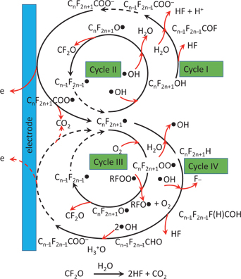
The proposed degradation mechanism of PFOA.
A similar decomposition mechanism was reported and the detailed mineralisation stage has been proposed for PFOA [36, 63], and shown in Figure 5. That is (in terms of Cycle I), after being decarboxylated, ●C7F15 radical is formed. This radical subsequently forms a thermally-unstable alcohol of C7F15OH after bening attacked by ●OH, and further deflourinate to C6F13COF. After being hydrolysed, it transforms to C6F13COOH (or C6F13COO−). The follow-up reaction repeats the similar degradation process / cycle until full degradation is achieved. This hypothesis was confirmed because the intermediates were detected using HPLC, which is the mainly-employed instrument for PFASs analysis at the current stage. However, the real degradation reaction might be complicated. In Figure 5, Cycles I-IV might proceed simultaneously and compete with each other [33].
Due to the high cost of BBD, MMO (mixed metal oxide) has received more attention recently. For example, SnO2, PbO2, MnO2, have been used to break down PFOA, with PbO2 showing the best result [48]. An issue is the possible damage to the MMO electrode’s surface due to fluorination [63]. Fortunately, the doping of F- might also benefit the degradation process [32]. But more research is needed.
A comparison of BDD, Ti-SnO2-Sb-Ce and Ti/SnO2-Sb/Ce-PbO2 electrodes has been carried out. Again, PbO2 has demonstrated a comparable performance with that of BDD [48, 64]. Also, the fluorination on the electrode surface has been confirmed, although its extent was proved not to be significant. Furthermore, the release of heavy metal from the electrode surface has been identified. Because the intermediates, such as the shorter chain of PFASs was not observed at obvious amount, it was concluded that the total degradation of PFNA / PFDA was quick [48].
In summary, the direct oxidation of PFASs plays an important role in their EAOP. At the very beginning of the degradation, the direct oxidation initialises the degradation process because the radical of ●HO cannot attack and degrade the PFASs alone. However, the initial oxidation generates PFAS radicals and activates them (as intermediates) to a higher energy level. Consequently, the subsequent reactions become possible with the involvement of the radical of ●HO. This means that the activated PFAS radical enables it to be attacked and broken down by the radical of ●HO.
The by-products should also be considered, including the release of HF, HOF, CF2, CF4, heavy metal ions, short chain PFASs, etc. If the initial reaction of PFASs is to decarboxylate or desulfonate, the pure F-C chain (such as CnF2n+1H, not radical of ●CnF2n+1) without carboxyl or sulfonate groups might be more stable and more difficult to be broken down. However, these intermediates have not been detected although they are shown in Figure 5(Cycle IV). Further research is needed for the whole process to be better understood, particularly the in-situ monitoring radicals will enrich the information for mechanism understanding, such as using electron paramagnetic resonance (EPR) [44].
4 Future outlook of EAOPs in PFASs degradation
4.1 Efficiency improvement
EAOP is attracting increasing interest from the environmental remediation community, particularly for the degradation of some POPs, such as PFOS / PFOA. Unfortunately, EAOP will attack all compounds in the EAOP cell, although their individual oxidation kinetics might be different [33, 65]. In this scenario what it usually required is pre-treatment or extraction to: firstly, improve the efficiency by focusing on PFASs; secondly, protect some useful moieties in the sample, such as biomas, nutrients, etc.; and thirdly, avoid toxic products such as ClO4− and prolong the shelf life of electrode [66].
The additives in the electrolyte might enhance the degradation efficiency by boosting the yielding rate of radicals, such as via the Fenton reaction [41], by generating other kinds of radicals rather than ●OH (such as ●SO42−), or by producing other oxidants simultaneously (such as O3, S2O82−, BiO3−, MnO4−, FeO42−, etc.). Further research should also address the cost issue, such as by replacing the electrode materials (of BDD) with cheap ones, using solar panels to power the EAOP, etc. [20, 30]
4.2 Electrode materials and cell improvement
Currently electrode materials like BDD are expensive [36, 49]. In fact, PbO2 has been reported as having a favourable performance, although its fabrication on wafer is a challenge too [48, 64]. Seeking a cheap replacement is thus urgent to significantly reduce the cost towards scale-up application. For example, the use of an iron electrode to generate FeO42− might be another alternative [67]. In this case, however, EAOP must be differentiated from electrocoagulation [68].
To improve the electrode’s shelf life, the anode materials can be modified, such as by doping and nanofabricating [31, 32, 36, 45]. For example, PbO2 doped with F- was found to inhibit O2 emission, accelerate oxidation and enhance degradation efficiency [32]. The explanation for is that the F- is incorporated into the bulk structure and decreases the extent of adsorbed water, for both α-PbO2 or β-PbO2, although the latter is preferred for water treatment [33]. Similarly, SnO2 doped with F- is also reportedly promising for highly efficient treatment of PFOA in waste water [69].
Further attention should also be paid to the cathode and the reactions occurring there [31]. As a compulsory component of an electrochemical cell, the cathode reaction should be designed to maximise its benefit towards the degradation process. The emission of hydrogen on the cathode surface, as well as the production of H2O2 [41], the reduction of metal ions (such as from Fe3+ to Fe2+) and the dechlorination and debromination of organohalogens should also be noticed [51, 55, 70, 71].
4.3 Beyond water: Soil
Because the generation of radicals occurs in aqueous media, EAOP is generally utilised to remediate waste water, including surface water and ground water. However, even for the water sample, EAOP usually needs a pre-treatment or extraction module to address issues of efficiency and anode shelf life, as discussed above. This pre-treatment module might also be used for soil remediation [21]. In this process the PFASs will be extracted from the contaminated soils and transformed to the water media [72]. Subsequently the EAOP will take over the degradation process.
Note, there are several options in terms of electrochemical remediation [31], such as electrocoagulation [73], electrokinetics [21], electrodeposition [29] and geooxidation [74, 75], etc. Among these, the geooxidation process showed promise in breaking down some POPs from soil. Interestingly, it based on a similar mechanism to that used in EAOP [76]. Further research is thus highly desirable. For example, a similar approach has been described using a bipolar electrode to enhance EAOP’s performance [51].
4.4 Combination with other approaches
To increase the efficiency of remediation, a series of remediation stages is usually developed to target different contaminants [20, 65]. Currently the EAOP is employed as the last stage of remediation to break down persistent contaminants [30, 73, 77]. The possible reasons for this include: (i) its powerful degradation capacity for POPs; (ii) its high cost; and (iii) electrode shelf life through fouling of the surface by heavily polluted samples.
There are numerous other remediation approaches and a combined solution might work more effectively than an individual one. For example, sonochemistry is another newly developed technology for remediation [78, 79]. The basic idea is that the sonication-generated micro-bubble will experience a high temperature of >5000 °C where H2O molecules can be split into the radicals of ●OH [26]. If EAOP is combined with this technology, the benefits will include: (i) improved radical generation efficiency [20]; (ii) accelerated transportation of POPs to and from the electrode surface [36]; and (iii) enhanced electrode self-cleaning function.
In general, with further investigation and development of the EAOP, wide applications for real sample remediation can be anticipated.
Acknowledgements
The authors kindly acknowledge funding support provided by CRC CARE and the Australian Government Department of Defence.
References
[1] Sauvé S, Desrosiers M. Chem Cent J. 2014;8:15–21.10.1186/1752-153X-8-15Suche in Google Scholar PubMed PubMed Central
[2] Petrie B, Barden R, Kasprzyk-Hordern B. Water Res. 2015;72:3–27.10.1016/j.watres.2014.08.053Suche in Google Scholar PubMed
[3] Buck RC, Franklin J, Berger U, Conder JM, Cousins IT, De Voogt P, et al. Integr Environ Assess Manag. 2011;7:513–541.10.1002/ieam.258Suche in Google Scholar PubMed PubMed Central
[4] Richardson SD, Kimura SY. Anal Chem. 2016;88:546–582.10.1021/acs.analchem.5b04493Suche in Google Scholar PubMed
[5] Richardson SD, Ternes TA. Anal Chem. 2005;77:3807–3838.10.1021/ac058022xSuche in Google Scholar PubMed
[6] McKenzie ER, Siegrist RL, McCray JE, Higgins CP. Environ Sci Technol. 2015;49:1681–1689.10.1021/es503676pSuche in Google Scholar PubMed
[7] Wang Z, Cousins IT, Scheringer M, Buck RC, Hungerbühler K. Environ Int. 2014;70:62–75.10.1016/j.envint.2014.04.013Suche in Google Scholar PubMed
[8] Wang Z, Cousins IT, Scheringer M, Buck RC, Hungerbühler K. Environ Int. 2014;69:166–176.10.1016/j.envint.2014.04.006Suche in Google Scholar PubMed
[9] Vierke L, Staude C, Biegel-Engler A, Drost W, Schulte C. Environ Sci Eur. 2012;24:16.10.1186/2190-4715-24-16Suche in Google Scholar
[10] Merino N, Qu Y, Deeb RA, Hawley EL, Hoffmann MR, Mahendra S. Environ Eng Sci 2016. 10.1089/ees.2016.0233.Suche in Google Scholar
[11] Carter KE, Farrell J. Environ Sci Technol. 2008;42:6111–6115.10.1021/es703273sSuche in Google Scholar PubMed
[12] Vecitis CD, Park H, Cheng J, Mader BT, Hoffmann MR. Front Environ Sci Eng China. 2009;3:129–151.10.1007/s11783-009-0022-7Suche in Google Scholar
[13] Naidu R. 5th International Contaminated Site Remediation Conference. Melbourne, Australia, 2013.10.1007/s11270-013-1705-zSuche in Google Scholar
[14] Kärrman A, Elgh-Dalgren K, Lafossas C, Møskeland T. Environmental Chemistry. 2011;8:372–380.10.1071/EN10145Suche in Google Scholar
[15] Place BJ, Field JA. Environ Sci Technol. 2012;46:7120–7127.10.1021/es301465nSuche in Google Scholar PubMed PubMed Central
[16] Cheng F, Zuliang C, Megharaj M, Naidu R. Environ Technol Innovation. 2016;5:52–59.10.1016/j.eti.2015.12.003Suche in Google Scholar
[17] Fang C, Megharaj M, Naidu R. RSC Adv. 2016;6:11140–11145.10.1039/C5RA26114GSuche in Google Scholar
[18] Fang C, Dharmarajan R, Megharaj M, Naidu R. Trac Trends Anal Chem. 2017;86:143–154.10.1016/j.trac.2016.10.008Suche in Google Scholar
[19] Fang C, Megharaj M, Naidu R. Electroanalysis. 2017;29:1–9.10.1002/elan.201780101Suche in Google Scholar
[20] Sirés I, Brillas E, Oturan MA, Rodrigo MA, Panizza M. Environ Sci Pollut Res. 2014;21:8336–8367.10.1007/s11356-014-2783-1Suche in Google Scholar PubMed
[21] Rodrigo MA, Oturan N, Oturan MA. Chem Rev. 2014;114:8720–8745.10.1021/cr500077eSuche in Google Scholar PubMed
[22] Han F, Kambala VSR, Srinivasan M, Rajarathnam D, Naidu R. Appl Catalysis A: Gen. 2009;359:25–40.10.1016/j.apcata.2009.02.043Suche in Google Scholar
[23] Bergmann MEH, Koparal AS, Iourtchouk T. Crit Rev Environ Sci Technol. 2014;44:348–390.10.1080/10643389.2012.718948Suche in Google Scholar
[24] Wang JL, Xu LJ. Crit Rev Environ Sci Technol. 2012;42:251–325.10.1080/10643389.2010.507698Suche in Google Scholar
[25] Attri P, Kim YH, Park DH, Park JH, Hong YJ, Uhm HS, et al. Sci Rep. 2015;5:9332.10.1038/srep09332Suche in Google Scholar PubMed PubMed Central
[26] Gligorovski S, Strekowski R, Barbati S, Vione D. Chem Rev. 2015;115:13051–13092.10.1021/cr500310bSuche in Google Scholar PubMed
[27] Trautmann AM, Schell H, Schmidt KR, Mangold K-M, Tiehm A. Water Sci Technol. 2015;71:1569–1575.10.2166/wst.2015.143Suche in Google Scholar PubMed
[28] Mitchell SM, Ahmad M, Teel AL, Watts RJ. Environ Sci Technol Lett. 2014;1:117–121.10.1021/ez4000862Suche in Google Scholar
[29] Vasudevan S, Oturan MA. Environ Chem Lett. 2013;12:97–108.10.1007/s10311-013-0434-2Suche in Google Scholar
[30] Feng L, Van Hullebusch ED, Rodrigo MA, Esposito G, Oturan MA. Chem Eng J. 2013;228:944–964.10.1016/j.cej.2013.05.061Suche in Google Scholar
[31] Martínez-Huitle CA, Rodrigo MA, Sirés I, Scialdone O. Chem Rev. 2015;115:13362–13407.10.1021/acs.chemrev.5b00361Suche in Google Scholar PubMed
[32] Li X, Pletcher D, Walsh FC. Chem Soc Rev. 2011;40:3879–3894.10.1039/c0cs00213eSuche in Google Scholar PubMed
[33] Chaplin BP. Environmental Science: Processes & Impacts. 2014;16:1182–1203.10.1039/C3EM00679DSuche in Google Scholar PubMed
[34] Radjenovic J, Sedlak DL. Environ Sci Technol. 2015;49:11292–11302.10.1021/acs.est.5b02414Suche in Google Scholar PubMed
[35] Garcia-Segura S, Keller J, Brillas E, Radjenovic J. J Hazard Mater. 2015;283:551–557.10.1016/j.jhazmat.2014.10.003Suche in Google Scholar PubMed
[36] Wu W, Huang Z-H, Lim T-T. Appl Catalysis A: Gen. 2014;480:58–78.10.1016/j.apcata.2014.04.035Suche in Google Scholar
[37] Chaplin M. Electrolysis of Water, 2012. Available at: http://www1.lsbu.ac.uk/water/electrolysis.html.Suche in Google Scholar
[38] Bard AJ, Faulkner LR. Electrochemical Methods: Fundamentals and Applications, 2nd ed. New York: Wiley, 2001.Suche in Google Scholar
[39] Bejan D, Guinea E, Bunce NJ. Electrochim Acta. 2012;69:275–281.10.1016/j.electacta.2012.02.097Suche in Google Scholar
[40] Jung Y, Hong E, Yoon Y, Kwon M, Kang J-W. Ozone: Sci Eng. 2014;36:515–525.10.1080/01919512.2014.956862Suche in Google Scholar
[41] Garcia-Segura S, Salazar R, Brillas E. Electrochim Acta. 2013;113:609–619.10.1016/j.electacta.2013.09.097Suche in Google Scholar
[42] Marcus RA. J Chem Phys. 1965;43:679–701.10.1063/1.1696792Suche in Google Scholar
[43] Awad MI, Sata S, Kaneda K, Ikematsu M, Okajima T, Ohsaka T. Electrochem Commun. 2006;8:1263–1269.10.1016/j.elecom.2006.06.008Suche in Google Scholar
[44] Duan X, Sun H, Kang J, Wang Y, Indrawirawan S, Wang S. ACS Catal. 2015;5:4629–4636.10.1021/acscatal.5b00774Suche in Google Scholar
[45] Urtiaga A, Fernández-González C, Gómez-Lavín S, Ortiz I. Chemosphere. 2015;129:20–26.10.1016/j.chemosphere.2014.05.090Suche in Google Scholar PubMed
[46] Kim K-W, Kim Y-J, Kim I-T, Park G-I, Lee E-H. Electrochim Acta. 2005;50:4356–4364.10.1016/j.electacta.2005.01.046Suche in Google Scholar
[47] Li M, Feng C, Hu W, Zhang Z, Sugiura N. J Hazard Mater. 2009;162:455–462.10.1016/j.jhazmat.2008.05.063Suche in Google Scholar PubMed
[48] Lin H, Niu J, Ding S, Zhang L. Water Res. 2012;46:2281–2289.10.1016/j.watres.2012.01.053Suche in Google Scholar PubMed
[49] Sopaj F, Rodrigo MA, Oturan N, Podvorica FI, Pinson J, Oturan MA. Chem Eng J. 2015;262:286–294.10.1016/j.cej.2014.09.100Suche in Google Scholar
[50] Fang C, Wu B, Zhou X. Electrophoresis. 2004;25:375–380.10.1002/elps.200305740Suche in Google Scholar PubMed
[51] Rajic L, Nazari R, Fallahpour N, Alshawabkeh AN. J Environ Chem Eng. 2016;4:197–202.10.1016/j.jece.2015.10.030Suche in Google Scholar PubMed PubMed Central
[52] Cremer D, Kraka E. Croat Chem Acta. 1984;57:1259–1281.Suche in Google Scholar
[53] Luo Y-R. Comprehensive handbook of chemical bond energies. Boca Raton: CRC press, 200710.1201/9781420007282Suche in Google Scholar
[54] Randazzo S, Scialdone O, Brillas E, Sirés I. J Hazard Mater. 2011;192:1555–1564.10.1016/j.jhazmat.2011.06.075Suche in Google Scholar PubMed
[55] Rajic L, Fallahpour N, Oguzie E, Alshawabkeh A. Electrochim Acta. 2015;181:118–122.10.1016/j.electacta.2015.03.112Suche in Google Scholar PubMed PubMed Central
[56] Liu CS, Shih K, Wang F. Separation Purif Technol. 2012;87:95–100.10.1016/j.seppur.2011.11.027Suche in Google Scholar
[57] Vecitis CD, Park H, Cheng J, Mader BT, Hoffmann MR. The Journal of Physical Chemistry A. 2008;112:4261–4270.10.1021/jp801081ySuche in Google Scholar PubMed
[58] Zhuo Q, Deng S, Yang B, Huang J, Wang B, Zhang T, et al. Electrochim Acta. 2012;77:17–22.10.1016/j.electacta.2012.04.145Suche in Google Scholar
[59] Bard AJ, Parsons R, Jordan J. Standard potentials in aqueous solution. New York: CRC press, 1985.Suche in Google Scholar
[60] Liao Z, Farrell J. J Appl Electrochemistry. 2009;39:1993–1999.10.1007/s10800-009-9909-zSuche in Google Scholar
[61] Niu J, Lin H, Xu J, Wu H, Li Y. Environ Sci Technol. 2012;46:10191–10198.10.1021/es302148zSuche in Google Scholar PubMed
[62] Houtz EF, Sutton R, Park J-S, Sedlak M. Water Res. 2016;95:142–149.10.1016/j.watres.2016.02.055Suche in Google Scholar PubMed
[63] Ochiai T, Iizuka Y, Nakata K, Murakami T, Tryk DA, Fujishima A, et al. Diam Relat Mater. 2011;20:64–67.10.1016/j.diamond.2010.12.008Suche in Google Scholar
[64] Lin H, Niu J, Xu J, Huang H, Li D, Yue Z, et al. Environ Sci Technol. 2013;47:13039–13046.10.1021/es4034414Suche in Google Scholar PubMed
[65] Griessler M, Knetsch S, Schimpf E, Schmidhuber A, Sommer R, Kirschner AKT, et al. Water Sci Technol. 2011;63:2010–2016.10.2166/wst.2011.444Suche in Google Scholar
[66] Carter KE, Farrell J. Environ Sci Technol. 2009;43:8350–8354.10.1021/es9017738Suche in Google Scholar
[67] Nam J-H, Kim I-K, Kwon J, Kim YD. Desalination and Water Treatment. 2016;57:5138–5145.10.1080/19443994.2014.1001440Suche in Google Scholar
[68] Lin H, Wang Y, Niu J, Yue Z, Huang Q. Environ Sci Technol. 2015;49:10562–10569.10.1021/acs.est.5b02092Suche in Google Scholar
[69] Yang B, Jiang C, Yu G, Zhuo Q, Deng S, Wu J, et al. J Hazard Mater. 2015;299:417–424.10.1016/j.jhazmat.2015.06.033Suche in Google Scholar
[70] Mao X, Ciblak A, Amiri M, Alshawabkeh AN. Environ Sci Technol. 2011;45:6517–6523.10.1021/es200943zSuche in Google Scholar
[71] Rajic L, Fallahpour N, Podlaha E, Alshawabkeh A. Chemosphere. 2016;147:98–104.10.1016/j.chemosphere.2015.12.095Suche in Google Scholar
[72] Mousset E. Integrated processes for removal of persistent organic pollutants: soil washing and electrochemical advanced oxidation processes combined to a possible biological post-treatment. Marne-la-Vallée: Université Paris-Est, 2013.Suche in Google Scholar
[73] Thiam A, Zhou M, Brillas E, Sirés I. J Chem Technol Biotechnol. 2014;89:1136–1144.10.1002/jctb.4358Suche in Google Scholar
[74] Rahner D, Ludwig G, Röhrs J. Electrochim Acta. 2002;47:1395–1403.10.1016/S0013-4686(01)00854-4Suche in Google Scholar
[75] Röhrs J, Ludwig G, Rahner D. Electrochim Acta. 2002;47:1405–1414.10.1016/S0013-4686(01)00855-6Suche in Google Scholar
[76] Jin S, Fallgren PH. J Hazard Mater. 2010;173:200–204.10.1016/j.jhazmat.2009.08.069Suche in Google Scholar PubMed
[77] Pociecha M, Lestan D. J Hazard Mater. 2012;201–202:273–279.10.1016/j.jhazmat.2011.11.092Suche in Google Scholar PubMed
[78] Zhao H, Gao J, Zhao G, Fan J, Wang Y, Wang Y. Appl Catalysis B: Environ. 2013;136–137:278–286.10.1016/j.apcatb.2013.02.013Suche in Google Scholar
[79] Rodriguez-Freire L, Balachandran R, Sierra-Alvarez R, Keswani M. J Hazard Mater. 2015;300:662–669.10.1016/j.jhazmat.2015.07.077Suche in Google Scholar PubMed
[80] Fang C, Megharaj M, Naidu R. Environ Toxicol Chem. 2015;34:2625–2628.10.1002/etc.3115Suche in Google Scholar PubMed
[81] Fang C, Megharaj M, Naidu R. Austin Environ Sci. 2016;1:1005.10.1021/acs.est.5b05024Suche in Google Scholar PubMed
[82] Niu J, Lin H, Gong C, Sun X. Environ Sci Technol. 2013;47:14341–14349.10.1021/es402987tSuche in Google Scholar PubMed
© 2017 Walter de Gruyter GmbH, Berlin/Boston
Artikel in diesem Heft
- Editorial
- Excitation Kinetics of Oxygen O(1D) State in Low-Pressure Oxygen Plasma and the Effect of Electron Energy Distribution Function
- Using amino-functionalized Fe3O4-WO3 nanoparticles for diazinon removal from synthetic and real water samples in presence of UV irradiation
- Treatment of high salinity wastewater using CWPO process for reuse
- Electrochemical Advanced Oxidation Processes (EAOP) to degrade per- and polyfluoroalkyl substances (PFASs)
- Effect of feedstock impurities on activity and selectivity of V-Mo-Nb-Te-Ox catalyst in ethane oxidative dehydrogenation
- Photocatalytic Degradation of Azo Dyes Over Semiconductors Supported on Polyethylene Terephthalate and Polystyrene Substrates
- Effects of calcination temperature on sol-gel synthesis of porous La2Ti2O7 photocatalyst on degradation of Reactive Brilliant Red X3B
- ClO2-oxidation-based demulsification of oil-water transition layer in oilfields: An experimental study
- Semi-permanent hair dyes degradation at W/WO3 photoanode under controlled current density assisted by visible light
- Degradation of PVA (polyvinyl alcohol) in wastewater by advanced oxidation processes
- Degradation of imidacloprid insecticide in a binary mixture with propylene glycol by conventional fenton process
- Gemini surfactant-assisted synthesis of BiOBr with superior visible light-induced photocatalytic activity towards RhB degradation
- Photocatalytic paraquat degradation over TiO2 modified by hydrothermal technique in alkaline solution
- Enhancement of Profenofos Remediation Using Stimulated Bioaugmentation Technique
- Mechanistic insight on the sonolytic degradation of phenol at interface and bulk using additives
- Biosolubilization of low-grade rock phosphate by mixed thermophilic iron-oxidizing bacteria
- Degradation of methyl orange using dielectric barrier discharge water falling film reactor
- Rapid prediction of hydrogen peroxide concentration eletrogenerated with boron doped diamond electrodes