Effect of different drilling techniques on high-cycle fatigue behavior of nickel-based single-crystal superalloy with film cooling hole
-
Zhijin Zhang
 and
Mingqi Zhang
and
Mingqi Zhang

Abstract
The flat plate specimens of nickel-based single-crystal superalloy with 14 film cooling holes, which made by different drilling techniques, were used to study the high-cycle fatigue (HCF) properties at 980°C in an ambient atmosphere. At the same time, the electrical discharge machining (EDM) specimens with a single hole were also used to study the HCF properties under different temperatures. The hole and fracture micrographs were analyzed by scanning electron microscope. The results indicated that different drilling techniques have a great influence on HCF life. The fatigue limit of the millisecond laser drilling is 353 MPa, while the EDM is 359 MPa and the electro-stream machining (ESM) is 378 MPa. The fatigue life decreases gradually with the temperature increasing. The fatigue limit of EDM specimens with a single hole at 900°C, 980°C, and 1,050°C are 472, 430, and 293 MPa, respectively. The destruction of the specimens is a typical multisource rupture, and the fracture morphology includes three parts: the cracks sources around the film cooling hole, the propagation zone along the {001} planes, and instant rupture zone along the {111} planes.
1 Introduction
The turbine is the largest component of thermal loads and mechanical loads in the aircraft engine; thus, the performance of the engine depends on the temperature of the turbine inlet [1]. The increasing turbine inlet temperature is an important means to improve engine performance. In recent years, the wide application of superalloy materials especially nickel-based single-crystal superalloy on turbine blades makes the inlet temperature of the turbine increase continuously [2,3,4,5,6]. However, the temperature resistance of the materials is limited [7]; the film cooling hole of turbine blade has been proven as an effective way to reduce the surface temperature of turbine blades. Consequently, the drilling technique of film cooling hole has become one of the key technologies of turbine blade manufacture. At present, laser drilling (LD), electrical discharge machining (EDM), and electric-stream machining (ESM) are widely used for film cooling holes [8], and different drilling techniques have their own advantages and disadvantages. LD and EDM are hot working techniques, but the ESM is a cold working technique. The drilling speed of LD is fast, but the recast layer and microcracks would be formed [9]. As for EDM, the recast layer is relatively thin than LD but there are still microcracks. ESM is based on electrochemical principles; hence, there is no recast layer, heat-affected zone, and microcracks.
The HCF fatigue caused by the vibration is inevitable during the service of the nickel-based single crystal turbine blades [10,11]. The integrity of the blade structure is damaged due to the presence of the film cooling hole, and it has been the weak links in the stress concentration and multi-axis stress states [12,13,14,15,16]. The drilling process might modify the original properties of the material around the hole and affect the mechanical properties. At the same time, the film cooling hole leaving on the surface of turbine blades will destroy the structural integrity of the material. Under the effect of porous interference, the local area of the film cooling hole becomes the multiple sites of the failure fracture. Hence, it is very important to study the life of the specimens with film cooling hole for the application of engine blade engineering.
The fatigue life of nickel-based single crystal blades with film cooling hole has attracted much attention from the researchers. Many researchers have studied the effect of different drilling techniques on material characterization. For instance, Liu et al. [17] studied the mainstream manufacturing process of the film cooling hole and analyzed the effect of drilling processes on fatigue performance. Wen et al. [18] compared the creep life of thin-wall plate specimens with cooling holes with specimens without holes and studied the effect of cooling holes on the creep life. Kliuev et al. [19] studied the effect of the EDM process on Inconel 718 and analyzed the factors of recast layer thickness. Gamage et al. [20] studied the influence of EDM parameters on the quality of the hole. Gemma and Phillips [21] predicted the life of different cooling hole configurations formed by LD, EDM, and electrochemical machining using fracture mechanics. However, the effect of different drilling techniques on the HCF properties of a nickel-based single crystal with film cooling holes has not been effectively carried out in the present literature.
The objective of the present work is to fill the gap in the literature, relating to the effect of different drilling techniques on HCF properties of a nickel-based single crystal with film cooling holes. The flat plate specimens of nickel-based single-crystal superalloy with film cooling holes were made by millisecond laser drilling (MSLD), EDM, and ESM. The effect of different drilling techniques and temperature on HCF properties was investigated.
2 Materials and methods
2.1 Experiment material
The second-generation single-crystal superalloy DD6 is used in the experiment. The single-crystal superalloy specimens with [001] orientation were cast by the helical crystal selection method and directionally solidified in the furnace of high-temperature gradient. The crystal orientations of the specimens were determined by the Laue X-ray back-reflection method. All the plates tested in this experiment had deviations within 5° from the perfect [001] direction.
Plate specimens with 14 holes are designed according to the complicated structure of the turbine blades. The schematic diagram of the plate is shown in Figure 1. The specimens with a single hole were introduced to study the effects of temperature on fatigue life. The schematic diagram of the plate is shown in Figure 2. The unit in Figures 1 and 2 is mm.

Specimen with 14 film cooling holes.

Specimen with a single hole.
2.2 Experiment method
All the HCF tests were carried out on the servo-hydraulic material testing system (GPS-100), and the temperature was limited in ±5°C. The stress ratio R of minimum to maximum stress is 0.1, and the loading frequency is 90 Hz. The tests of specimens with 14 film cooling holes were conducted at 980°C in an ambient atmosphere. The tests of specimens with a single film cooling hole were conducted at 900°C, 980°C, and 1,050°C in an ambient atmosphere. The experimental program was stress-controlled with trapezoidal load waveforms which is shown in Figure 3. All the test data were recorded by the computer automatically. Fracture surfaces and micrographs of the holes were observed using scanning electric microscopy (SEM; Hitachi S-4800) after ultrasonic cleanout.

Load waveforms of the HCF test.
3 Results and discussion
3.1 Microstructure of the film cooling hole
Micrographs of film cooling hole in different drilling techniques are shown in Figure 4. The micrographs of MSLD, EDM, and ESM are shown in Figure 4a–f, respectively. It can be seen from Figure 4 that both MSLD and EDM have recast layers around the film cooling hole whereas ESM does not. The reason is that the MSLD and EDM are all belonged to hot working, but the ESM is cold working. Figure 4a shows that the recast layer thickness of MSLD is about 43 µm. The high temperature in the processing process separates a large number of elements around the hole, and the final major residual component is carbides and oxides of cobalt and nickel. Consequently, the out-layer materials of the recast layer are loose, there are several microcracks such as Letter A in the recast layer as shown in Figure 4b, and Letter B is a magnify micrograph of Letter A. It is obvious that there are microcracks existing in the recast layer during the MSLD process. The microcracks are likely to become the original positions of the high-cycle fatigue (HCF) cracks of the material and gradually expand under the continuous action of the cyclic load. As for EDM, the recast layer is about 35 µm, and it is thinner than MSLD. No obvious microcracks are observed in the inner wall of the film cooling hole.

Micrographs of film cooling holes (a and b) MSLD, (c and d) EDM, and (e and f) ESM.
The micrograph of ESM is significantly different from the MSLD and EDM. The film cooling hole of ESM shows regular round, and the inner wall is smoother. There is no recast layer, and the heat-affected zone can be found around the hole. As ESM is mainly through the dissolution of the anode metal to achieve the hole, the recast layer and microcracks can be avoided.
3.2 Effect of different drilling techniques on fatigue strength
S–N curves of fatigue testing for MSLD, EDM, and ESM specimens with 14 film cooling holes at 980°C are shown in Figure 5. The triangles, squares, and circles are representing MSLD, EDM, and ESM, respectively. The arrows indicate that the specimens were no failures during the tests. It can be seen from Figure 5 that S–N curves of different drilling techniques show a general trend that the fatigue strength decreases with the stress increasing. Moreover, at the same stress amplitude, the fatigue life of the ESM specimens is longer than that of the MSLD and EDM. The fatigue limit of MSLD is 353 MPa, while EDM is 359 MPa and ESM is 378 MPa. The fatigue limit of ESM is higher than other drilling techniques. The fatigue limit of ESM is higher than that of MSLD 25 MPa that is 7.1%. Meanwhile, the fatigue limit of ESM is higher than that of EDM 19 MPa that is 5.3%.

S–N curve of different drilling techniques specimens at 980°C.
The fatigue limit of the material is determined by the up-and-down fatigue test method. The tests carried out in the present study are in accordance with the test standard (metal material axial loading fatigue test method) [22]. The fatigue limit σ D can be written as follows:
where m is the total number of valid tests, N is the stress level series, V i is the number of tests under the i stress level, and σ i is the stress level i.
The S–N curves were obtained by non-linear fitting with the Basquin equation [23], which can be written as follows:
where σ
a is the alternating stress,
The parameters of the Basquin equations and the fatigue limits of different drilling techniques are listed in Table1.
Parameters of the Basquin equations and fatigue limits
|
|
b | σ D/MPa | |
|---|---|---|---|
| MSLD | 868 | −0.054 | 353 |
| EDM | 1,452 | −0.083 | 366 |
| ESM | 2,535 | −0.115 | 378 |
3.3 Fractography
To understand the behavior of fatigue crack initiation and propagation clearly, the failed specimens fracture surfaces with 14 holes of different drilling techniques were examined.
Figure 6 shows the macroscopic fracture morphology of the MSLD specimen. Figure 6a is a fracture profile of the specimen. It can be seen that under the action of high temperature and alternating load, crack initiate from the edge of the middle hole at first and then propagate along the path between the hole. Figure 6b is a fracture surface near the hole. We can see that the fracture surface of the hole is made up of several inclined planes, and the normal direction of A plane (001) is parallel to the loading direction. The angle between the normal direction of B plane and loading direction is 45°–50°; it can be confirmed from the crystal theory that B plane is (111) plane. Generally speaking, if there is no interaction between porous, the cracks will propagate along (001). But the stress is complex because of the several holes under interaction, then the propagation mechanism may be different.
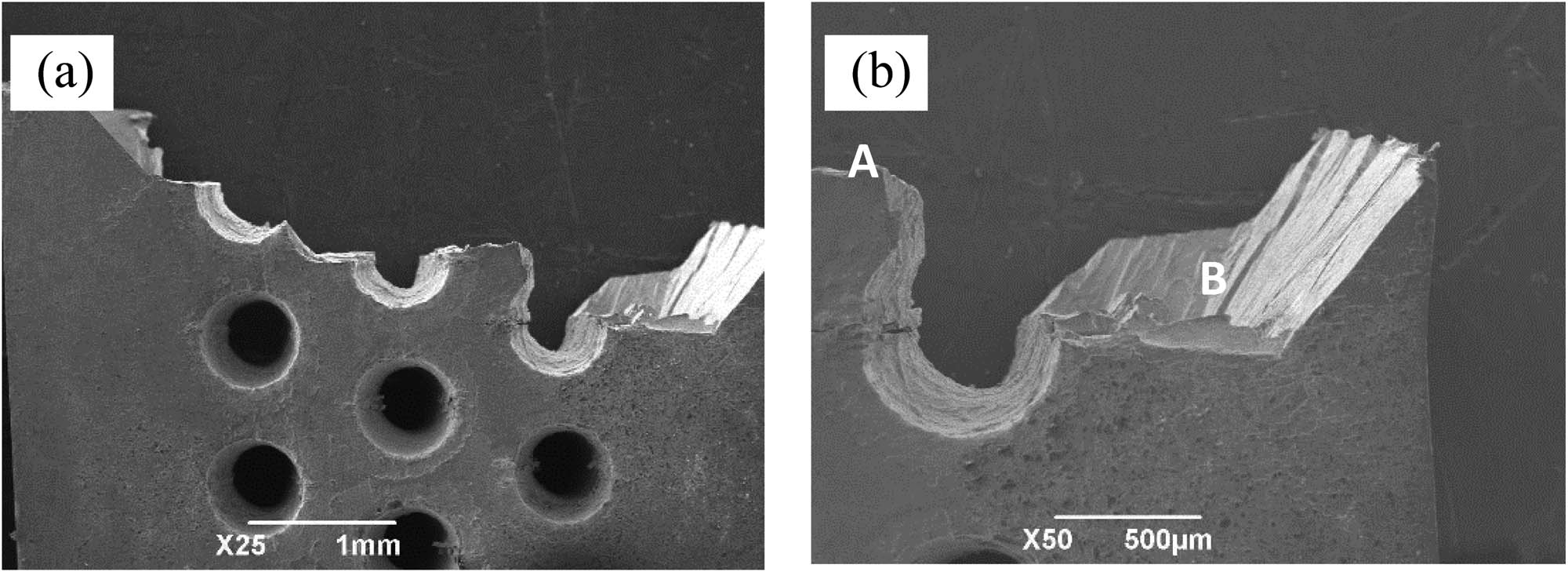
Macroscopic fracture morphology of MSLD specimen: (a) fracture profile and (b) fracture surface near the hole.
The fracture morphologies of MSLD, EDM, and ESM are shown in Figures 7–9, respectively. From the fracture morphologies, it can be concluded that different drilling techniques have similar morphologies. And, there are multiple fatigue sources for the fracture morphology of the specimens after HCF tests at 980°C under different stress amplitudes. During the crack propagation, fatigue cracks expand from outmost surfaces deep into interior along the primary slip plane under the alternative stress. Figure 7a is the macroscopic fracture morphology of MSLD, and there are two different areas indicated by 1 and 2. Figure 7b is the magnify micrograph of hole 1 in Figure 7a. It can be seen that the cracks propagate along the {001} planes and the bright shell area can be found, but no obvious river strip and ladder fracture characteristics exist. Thus, we can infer that the area surrounds the film cooling hole is the crack extension area. Figure 7c is the magnify micrograph of hole 2 in Figure 7a. As can be seen from Figure 7c that the letter A which has similar morphologies with hole 1 is the crack propagation area of hole 2. However, the length of the crack propagation area is only 0.4335 mm. The letter B in Figure 7c is an instant rupture zone which is along the {111} planes and has the ladder fracture characteristics. Figure 7d is the magnify micrograph of the shell area in Figure 7b. It can be seen from Figure 7d that the crystal grain is complete and slightly oxidized. The EDS analysis of oxides in Figure 7d is shown in Figure 7e. Figure 8 shows the macroscopic fracture morphology of the EDM specimen. As can be seen, it is obviously different from the fracture morphology of MSLD. There is no shell area and it si typical crisp fracture. Figure 9 shows the macroscopic fracture morphology of the ESM specimen. We can see that there are many tear ridges along the hole edge, and the crack propagates from the hole edge to both sides of the hole. In summary, typical fatigue morphology includes fatigue source area, crack propagation area, and instant rupture zone. There is no recast layer and a heat-affected zone can be found around the hole of ESM. As ESM is mainly through the dissolution of the anode metal to achieve the hole, the recast layer and heat-affected zone can be avoided. Fewer microcracks can be found around film holes. Fatigue is most sensitive to defects such as cracks; therefore, ESM is better than the others.

Fracture morphology of MSLD: (a) macroscopic fracture morphology, (b) middle hole fracture morphology, (c) edge hole fracture morphology, (d) shell area, and (e) the EDS analysis of oxides.

Fracture morphology of EDM: (a) Macroscopic fracture morphology, (b) Microscopic fracture morphology.

Fracture morphology of ESM: (a) Macroscopic fracture morphology, (b) Microscopic fracture morphology.
3.4 Effect of temperature on fatigue strength
S–N curves of fatigue testing for EDM specimens with single film cooling holes at 900, 980, and 1,050°C are shown in Figure 10. According to Figure 10, the temperature makes a significant influence on the fatigue limit. As the temperature increases, the fatigue life decreases gradually. The fatigue limit of the specimen is 472 MPa at 900°C. The fatigue limit of specimen decreased to 42 MPa, i.e., 430 MPa with an attenuation rate of 2.25 MPa/10°C while the temperature increased from 900 to 980°C. But the fatigue limit of specimen sharply decreased when the temperature is 1,000°C. The fatigue limit of the specimen is 293 MPa at 1,050°C. Comparing the fatigue limit of the specimen at 1,050 to 980°C, it can be found that the fatigue limit decreased to 137 MPa with an attenuation rate of 19.57 MPa/10°C. Consequently, the attenuation rate of the fatigue limit increases with the temperature rising.

S–N curve of single hole specimens HCF tested at different temperatures.
The parameters of the Basquin equations and the fatigue limits of different drilling techniques are listed in Table 2.
Parameters of the Basquin equations and fatigue limits
| T/°C |
|
b | σ D/MPa |
|---|---|---|---|
| 900 | 1,134 | −0.052 | 472 |
| 980 | 1,544 | −0.076 | 430 |
| 1,050 | 2,523 | −0.128 | 293 |
As for the specimens with a single hole, the film cooling hole destroyed the integrity of the structure, and as a result, the microcracks will occur around the hole. The HCF tests of specimens without any hole were carried out, and the fracture morphology is shown in Figure 11. It can be seen that the severe stress concentration is first generated at the casting defect, which is the primary location of crack initiation. For specimens with a film cooling hole, the cracks occur around the hole. For specimens without any hole, the cracks occur at the defects.

Fracture morphology of specimens without any hole.
The crack initiation has a close relationship with temperature. In engineering practice, q is commonly used to characterize the notch sensitivity of structures. Usually, the notch sensitivity q was defined as follows [24]:
where K f is the fatigue notch factor and K t is the theoretical stress concentration factor, which defined as follows:
where
The value of q varies from q = 0 or no notch effect to q = 1 or full theoretical effects. The notch sensitivity of the specimens with a single hole under different temperatures is listed in Table 3. It can be seen from Table 3, the notch sensitivity increases with the temperature increases, and the notch sensitivity at 900, 980 and 1,050°C is 0.012, 0.085, and 0.027, respectively. The higher the notch sensitivity is, the easier the crack initiation around the film cooling hole and the lower of the fatigue life.
Notch sensitivity under different temperatures
| T/°C | q |
|---|---|
| 900 | 0.012 |
| 980 | 0.085 |
| 1,050 | 0.227 |
To investigate the microstructure changes after HCF deformation under different temperatures, the γ/γ′ microstructure of the specimens with a single hole was observed by SEM. The microstructure of the specimens at 980°C is shown in Figure 12. The microstructure of the original specimen is shown in Figure 12a, which has the typical phase of γ and γ′ [25]. The microstructure of the specimen after the HCF test is shown in Figure 12b. The images are taken from the position shown in Figure 13. The change of γ′ shape is related to time and temperature. Generally, the longer the time, the higher the temperature, and the more obvious the change of γ′ shape is. The change of γ′ shape generally occurs in the creep process. For high-cycle fatigue, due to the short time and low stress, no obvious plastic deformation can be observed. Although there is stress concentration, it has little effect on the change of γ′ shape. Comparing Figure 12a and b, it is interesting to notice that the shape of γ′ changed severely after the HCF test. The shape of γ′ changed from regular cube to irregular cube. The γ′ particles show a tendency to dissolve into the γ matrix. The change of γ′ shape only occurred in some localized areas closed to the specimen surface near the hole where the maximum stress amplitude was implemented.

Microstructures of the specimens: (a) original specimen and (b) after the HCF test.

The position where the images are taken from.
4 Conclusion
The effect of different drilling techniques on HCF lives of single-crystal superalloy DD6 specimens with 14 film cooling holes at 980°C was investigated. The specimens with a single hole were also used to study the HCF properties under different temperatures. The main conclusions could be drawn as follows:
The fatigue strength decreases with the stress increasing for different drilling techniques. At the same stress amplitude, the fatigue life of the ESM specimens is longer than that of the MSLD and EDM.
At 980°C, the fatigue limit of ESM is 378 MPa, while EDM is 359 MPa and MSLD is 353 MPa.
The fracture characteristics of different drilling techniques are similar that all belong to the multisource fracture. The fracture includes three parts: the cracks sources around the film cooling hole, the propagation zone along the {001} planes, and the instant rupture zone along {111} planes.
-
Funding information: This work was supported by the National Natural Science Foundation of China.
-
Author contributions: Zhijin Zhang performed the data analyses and wrote the manuscript; Mingqi Zhang contributed to the conception of the study.
-
Conflict of interest: The authors declared that they have no conflicts of interest to this work. We declare that we do not have any commercial or associative interest that represents a conflict of interest in connection with the work submitted.
-
Data availability statement: All data generated or analyzed during this study are included in this article.
References
[1] Kumari, S., D. V. V. Satyanarayana, and M. Srinivas. Failure analysis of gas turbine rotor blades. Engineering Failure Analysis, Vol. 45, 2014, pp. 234–244.10.1016/j.engfailanal.2014.06.003Search in Google Scholar
[2] Holländer, D., D. Kulawinski, A. Weidner, M. Thiele, H. Biermann, and U. Gampe. Small-scale specimen testing for fatigue life assessment of service-exposed industrial gas turbine blades. International Journal of Fatigue, Vol. 92, 2016, pp. 262–271.10.1016/j.ijfatigue.2016.07.014Search in Google Scholar
[3] Liu, L., J. Meng, J. Liu, T. Jin, X. Sun, and H. Zhang. Effect of crystal orientations on the cyclic deformation behavior in the low cycle fatigue of a single crystal nickel-base superalloy. Materials and Design, Vol. 131, 2017, pp. 441–449.10.1016/j.matdes.2017.06.047Search in Google Scholar
[4] Maktouf, W., K. Ammar, I. Ben Naceur, and K. SaÏ. Multiaxial high-cycle fatigue criteria and life prediction: application to gas turbine blade. International Journal of Fatigue, Vol. 92, 2016, pp. 25–35.10.1016/j.ijfatigue.2016.06.024Search in Google Scholar
[5] Hong, H. U., J. G. Kang, B. G. Choi, I. S. Yoo, and C. Y. Jo. A comparative study on thermomenchanical and low cycle fatigue failures of a single crystal nickel-based superalloy. International Journal of Fatigue, Vol. 33, 2011, pp. 1592–1599.10.1016/j.ijfatigue.2011.07.009Search in Google Scholar
[6] Zhang, Y., Z. Wen, H. Pei, J. Wang, Z. Li, and Z. Yue. Equivalent method of evaluating mechanical properties of perforated Ni-based single crystal plates using artificial neural networks. Computer Methods in Applied Mechanics and Engineering, Vol. 360, 2020, id. 112725.10.1016/j.cma.2019.112725Search in Google Scholar
[7] Lanzillotta, F., A. Sciacchitano, and A. G. Rao. Effect of film cooling on the aerodynamic performance of an airfoil. International Journal of Heat and Fluid Flow, Vol. 66, 2017, pp. 108–120.10.1016/j.ijheatfluidflow.2017.05.011Search in Google Scholar
[8] Reed, R. C. The superalloys: fundamentals and applications, Cambridge, CUP, 2006.10.1017/CBO9780511541285Search in Google Scholar
[9] Morar, N., R. Roy, J. Mehnen, J. R. Nicholls, and S. Gray. The effect of trepanning speed of laser drilled acute angled cooling holes on the high temperature low cycle corrosion fatigue performance of CMSX-4 at 850°C. International Journal of Fatigue, Vol. 102, 2017, pp. 112–120.10.1016/j.ijfatigue.2017.04.017Search in Google Scholar
[10] Zhang, D., J. Hong, Y. Ma, and L. Chen. A probability mechod for prediction on high cycle fatigue of blades caused by aerodynamic loads. Advances in Engineering Software, Vol. 42, 2011, pp. 1059–1073.10.1016/j.advengsoft.2011.07.010Search in Google Scholar
[11] Lukas, P, L. Kunz, and M. Svoboda. High cycle fatigue of superalloy single crystals at high mean stress. Materials Science and Engineering A, Vol. 387–389, 2004, pp. 505–510.10.1016/j.msea.2004.01.093Search in Google Scholar
[12] Ridong, L., Z. Zhengxing, Z. Wensheng, and F. Boyuan. The modal characteristic study of turbine blades. Transactions of Csice, Vol. 4, 1998, pp. 46–54.Search in Google Scholar
[13] Yangde, O., K. Ruilian, and S. Zhaohong. Vibration characteristics analysis for a shrouded turbine blade with air-cooling holes. Journal of Aerospace Power, Vol. 3, 1997, pp. 12–15.Search in Google Scholar
[14] Wen, Y., D. Farong, and H. Yong. Investigation of dynamic response property of wide chord hollow fan balde. Journal of Aerospace Power, Vol. 22, No. 3, 2007, pp. 444–449.Search in Google Scholar
[15] Junfeng, X., Z. Baotian, and F. Zhenping. Study on 3D finite element analytic method for vibration characteristics if cooling blade with thermal field. Gas Turbine Technology, Vol. 19, No. 3, 2006, pp. 28–31.Search in Google Scholar
[16] Wu, L., and G. Bai. Effect of film-hole on vibration characteristics of turbine blade. Aeroengine, Vol. 41, No. 6, 2015, pp. 54–58.Search in Google Scholar
[17] Liu, X., C. Tao, C. Liu, C. Y. Hu, and X. Chen. Investigation of processing methods and development of gas holes of engine blade. Materials Review. Vol. 27, No. 11, 2013, pp. 117–120.Search in Google Scholar
[18] Wen, Z., H. Pei, H. Yang, Y. Wu, and Z. Yue. A combined CP theory and TCD for predicting fatigue lifetime in single-crystal superalloy plates with film cooling holes. International Journal of Fatigue, Vol. 111, 2018, pp. 243–255.10.1016/j.ijfatigue.2018.02.020Search in Google Scholar
[19] Kliuev, M., M. Boccadoro, R. Perez, W. Dal Bó, J. Stimimann, F. Kuster, and K. Wegener. EDM Drilling and Shaping of Cooling Holes in Inconel 718 Turbine Blades. Procedia Cirp, Vol. 42, 2016, pp. 322–327.10.1016/j.procir.2016.02.293Search in Google Scholar
[20] Gamage, J. R, A. K. M. Desilva, C. Harrison, and D. Harrison. Ascertaining Life Cycle Inventory Data for Electrical Discharge Machining, ProcediaCirp, Vol. 41, 2016, pp. 908–913.10.1016/j.procir.2015.12.091Search in Google Scholar
[21] Gemma, A. E., and J. S. Phillips. The application of fracture mechanics to life prediction of cooling hole configurations in thermal-mechanical fatigue. Engineering Fracture Mechanics, Vol. 9, 1977, pp. 25–36.10.1016/0013-7944(77)90049-2Search in Google Scholar
[22] China Aviation Industry Corporation. Metal material axial loading fatigue test method. 1996.Search in Google Scholar
[23] ASTM. Annual Book of ASTM Standard E606. Vol. 03.01. Phiadelphia, PA, 1996.Search in Google Scholar
[24] Lukáš, P., L. Kunz, and M. Svoboda. Fatigue notch sensitivity of ultrafine-grained copper. Materials Science and Engineering A, Vol. 391, 2005, pp. 337–341.10.1016/j.msea.2004.09.052Search in Google Scholar
[25] Wen, Z., D. Zhang, S. Li, Z. Yue, and J. Gao. Anisotropic creep damage and fracture mechanism of nickel-base single crystal superalloy under multiaxial stress. Journal of Alloys and Compounds, Vol. 692, 2017, pp. 301–312.10.1016/j.jallcom.2016.09.052Search in Google Scholar
© 2021 Zhijin Zhang and Mingqi Zhang, published by De Gruyter
This work is licensed under the Creative Commons Attribution 4.0 International License.
Articles in the same Issue
- Research Articles
- Fused deposition modeling of poly(ether ether ketone) scaffolds
- Investigation of the microstructure evolution in TP347HFG austenitic steel at 700°C and its characterization method
- Hot deformation behavior and processing maps of 9Cr3W3Co oxide dispersion-strengthened steel
- Evolution of physicochemical properties of quick lime at converter-smelting temperature
- Influence of phase distribution of converter slag microzones on the occurrence of P
- Investigation on ultrasonic assisted friction stir welding of aluminum/steel dissimilar alloys
- Analysis of oxide scale thickness and pores position of HCM12A steel in supercritical water
- Behavior of MnS inclusions during homogenization process in low-alloyed steel FAS3420H
- Preparation and cutting performance of nano-scaled Al2O3-coated micro-textured cutting tool prepared by atomic layer deposition
- Prediction of hot metal temperature based on data mining
- Effect of TiO2 content in slag on Ti content in molten steel
- Performance evaluation of titanium-based metal nitride coatings and die lifetime prediction in a cold extrusion process
- Effect of different drilling techniques on high-cycle fatigue behavior of nickel-based single-crystal superalloy with film cooling hole
- Effect of CO2 injection into blast furnace tuyeres on the pulverized coal combustion
- Microstructure and properties of Co–Al porous intermetallics fabricated by thermal explosion reaction
- Evolution regularity of temperature field of active heat insulation roadway considering thermal insulation spraying and grouting: A case study of Zhujidong Coal Mine, China
- Evolution of reduction process from tungsten oxide to ultrafine tungsten powder via hydrogen
- A thermodynamic assessment of precipitation, growth, and control of MnS inclusion in U75V heavy rail steel
- Effect of basicity on the reduction swelling properties of iron ore briquettes
- Effect of Cr and Al alloying on the oxidation resistance of a Ti5Si3-incorporated MoSiBTiC alloy
- Microstructure and mechanical properties of 2060 Al–Li alloy welded by alternating current cold metal transfer with high-frequency pulse current
- Effects of composition and strain rate on hot ductility of Cr–Mo-alloy steel in the two-phase region
- Effect of K and Na on reduction swelling performance of oxidized roasted briquettes
- Dephosphorization mechanism and phase change in the reduction of converter slag
- Parametric investigation and optimization for CO2 laser cladding of AlFeCoCrNiCu powder on AISI 316
- Optimization of heat transfer and pressure drop of the channel flow with baffle
- Quantitative analysis of microstructure and mechanical properties of Nb–V microalloyed high-strength seismic reinforcement with different Nb additions
- Visualization of the damage evolution for Ti–3Al–2Mo–2Zr alloy during a uniaxial tensile process using a microvoids proliferation damage model
- Research on high-temperature mechanical properties of wellhead and downhole tool steel in offshore multi-round thermal recovery
- Dephosphorization behavior of reduced iron and the properties of high-P-containing slag
- Jet characteristics of CO2–O2 mixed injection using a dual-parameter oxygen lance nozzle for different smelting periods
- Effects of ball milling on powder particle boundaries and properties of ODS copper
- Heat transfer behavior in ultrahigh-speed continuous casting mold
- Solidification microstructure characteristics of Cu–Pb alloy by ECP treatment
- Luminescence properties of Eu2+ and Sm3+ co-doped in KBaPO4
- Research on high-temperature oxidation resistance, hot forming ability, and microstructure of Al–Si–Cu coating for 22MnB5 steel
- The differential analysis for temperature distribution diagnostics of arc current-carrying region in sheet slanting tungsten electrode inert gas welding with the electrostatic probe
- Reactions at the molten flux-weld pool interface in submerged arc welding
- The effect of liquid crystalline graphene oxide compared with non-liquid crystalline graphene oxide on the rheological properties of polyacrylonitrile solution
- Study on manganese volatilization behavior of Fe–Mn–C–Al twinning-induced plasticity steel
- Physical modeling of bubble behaviors in molten steel under high pressure
- Rapid Communication
- The new concept of thermal barrier coatings with Pt + Pd/Zr/Hf-modified aluminide bond coat and ceramic layer formed by PS-PVD method
- Topical Issue on Science and Technology of Solar Energy
- Solution growth of chalcopyrite Cu(In1−xGax)Se2 single crystals for high open-circuit voltage photovoltaic device
- Copper-based kesterite thin films for photoelectrochemical water splitting