Induced-Pitting Behaviors of MnS Inclusions in Steel
-
Shufeng Yang
 ,
Mengjing Zhao
,
Mengjing Zhao

Abstract
This paper investigated the effects of MnS inclusions on inducing pitting in steel. Three different cooling methods were used to control the morphology, size, and distribution of MnS inclusions. AC (alternating current) impedance spectroscopy experiments and potentiodynamic polarization experiments were carried out for different sizes of MnS inclusions. The corrosion immersion experiment was conducted to study the pitting corrosion process in different morphologies of MnS inclusions. The experiment results showed that pitting corrosion occurred around MnS inclusions and pitting was induced along the junction of MnS inclusions and their surrounding steel matrix. Also, the sensitivity of inducing-pitting of MnS inclusions was changed with the change of the average size of MnS in steel and it had a critical size of MnS. The deeper the MnS inclusions were buried in steel matrix, the more difficult it was for it to dissolve and fall off. Herein, it would cause greater damage.
Introduction
Steel is the most widely-used metal materials at present. However, corrosion, as the most common phenomenon, would cause great damage to the steel material and it also causes huge losses to human beings. The harm of corrosion is not only reflected in economic losses and casualties, but also in environmental pollution and hindrance to the development of emerging technologies. Materials corrosion consumes a great deal of precious, limited resources and energy. So, how to study and solve the corrosion problem in steel materials has become a popular topic.
There are two forms of steel corrosion: general corrosion and local corrosion. Pitting corrosion is one of the main forms of local corrosion, which is divided into two stages: pitting induced and pitting propagate [1]. Pitting-induced sensitivity, pitting extension tendency, and extension speed are the important parameters to study corrosion resistance of steel. Many studies [2, 3, 4, 5] have shown that the effect of inclusions on pitting-induced susceptibility can play an important role to further improve the corrosion resistance of steel.
Sulfide is one of the most common inclusions in steel. It not only has an important effect on the mechanical properties of steel, but also it has an effect on pitting corrosion resistance. Pitting corrosion of steel often occurred around the sulfide [6]. Due to the low melting point of FeS, it could lead to heat brittleness in steel. Thus, generally, adding a certain amount of Mn to form MnS which has a high melting point can help eliminate the damage of FeS. Therefore, sulfide inclusions in steel mainly refers to MnS inclusions [7]. So, in order to improve the corrosion resistance of steel, it is necessary to effectively control the characteristics of MnS inclusions [8].
Nowadays, many researchers have focused their studies on the effect of characteristics of MnS on inducing pitting corrosion of steel. Muto et al. [9] have studied the relationship of pitting corrosion with sulfide and oxide inclusions in 304 stainless steel and observed that MnS/CrS inclusions were more likely to induce pitting corrosion than MnO/CrO inclusions and pitting occurred on the boundary of MnS inclusions and steel matrix. Schmuki et al. [10] investigated the corrosion experiment in high-sulfur stainless steel DIN 1.4305. It was showed that during the corrosion, dissolution preferentially occurred around MnS inclusions and then pitting corrosion happened. In 316 L stainless steel, Hara et al. [11] explored to improve corrosion resistance by potentiostatic removal of surface MnS inclusions. They demonstrated the dissolution of MnS induced pitting corrosion. Herein, MnS inclusions are the major source of inducing-pitting corrosion in steel. However, there is a controversy on the mechanism of the pitting corrosion. At the same time, the characteristics of MnS inclusions also have an important influence on pitting corrosion. This paper discussed the relationship of different sizes and distributions of MnS inclusions with pitting corrosion. And as for the process of pitting corrosion induced by MnS inclusions in different morphologies, it conducted a comprehensive analysis. This study would provide a reference for improving corrosion resistance of steel by controlling the MnS inclusions.
Experimental
Experiment materials preparation
The experiment used pure industrial iron as the raw material. And electrolytic manganese (purity>98 %) and FeS (analytical grade) were added to adjust the steel composition, as shown in Table 1. A tubular silicon molybdenum resistance furnace was used as the heating equipment. And high purity argon was adopted to protect in the whole experiment process.
The composition of the steel (Mass Percent/mass %).
| C | Si | Mn | P | S | Al | Ni | Cr | Cu | Ti | O |
|---|---|---|---|---|---|---|---|---|---|---|
| 0.006 | 0.03 | 1.11 | 0.010 | 0.25 | 0.03 | 0.03 | 0.02 | 0.03 | 0.02 | 0.00144 |
Experimental methods
MnS inclusions control
The size and distribution of MnS inclusions were controlled by different cooling methods. The samples containing the MnS inclusions were heated to 1873 K for 0.5 h to preserve the temperature in a tube-type silicon molybdenum resistance furnace. The samples were cooled by means of furnace cooling, air cooling and water cooling, respectively. The size and distribution of inclusions were analyzed by SEM and Image Pro Plus.
Electrochemical experiments
Electrochemical experiments include potentiodynamic polarization experiment and electrochemical impedance spectroscopy (EIS). Electrochemical work-station and three-electrodes tests were also carried out for the polarization test in 3 % NaCl solution at 298 K. And platinum electrode was used as auxiliary electrode. The sample was working electrode and saturated calomel electrode (SCE) was reference electrode.
AC Impedance Experiment
AC impedance spectrum experiments were carried out for three different sizes of MnS inclusions. In this experiment, the sine wave potential amplitude was 10 mV and the range of frequency scanning was from 10 mH to 100 kHz. Nova software (Version 1.11, Metrohm Autolab B.V., The Netherlands) was used to analyze the experimental results.
Potentiodynamic Polarization Experiment
The study adopted potentiodynamic scanning polarization, with a scan rate of 0.5 mV/s. The experiment results were analyzed by Nova software. The polarization current density of 100 μA cm−2 and the corresponding value of polarization potential was the pitting potential according to ASTM·G150-99 (2004).
Corrosion immersion experiment
Under room temperature (298 K), the samples were corroded in the 6 % FeCl3 solution for different times. The micro corrosion morphology of samples was observed and analyzed by SEM and Image Pro Plus.
Results and discussions
MnS inclusions control and characteristics
Different sizes of sulfide inclusions were obtained by controlling the cooling rate of steel. And the typical SEM Images of MnS inclusions under different cooling methods are shown as Figure 1.

Typical images of SEM under different cooling methods for MnS inclusions. (a): furnace cooling; (b): air cooling; (c): water cooling.
Three different cooling methods determined the different cooling rates. From Figure 1, with the cooling rate of steel increasing, the average size of the inclusions was decreased. The size of MnS in the samples which were cooled by furnace cooling was largest. And the sample with smallest size MnS was cooled by water. Through calculating the size of the inclusions by Image Pro Software (Version 6.0, Media Cybernetics, Inc. Rockville, MD, USA), it was shown that with the increase of cooling rate, the number of large inclusions was decreased and the number of small inclusions was increased. On one hand, owing to the increase of cooling rate, the size of precipitated sulfide became smaller. On the other hand, the large cooling rate caused MnS being not enough time to precipitate and the solid solution of Mn and S in the steel were in super-saturation. So, MnS inclusions trended to be spherical in shape. And the observed globular sulfide was generated during the insulating process [12].
In terms of sulfide inclusions morphology, the most significant factor affecting sulfide morphology is the oxygen content [13]. Under three cooling methods, the oxygen content remained a low and stable level. At the same time, there was an higher sulfur content in steel [14, 15, 16]. Therefore, the sulfide inclusions were mainly spherical and spindle, with a small amount of strip shapes and chains through three cooling methods.
Electrochemical experiment and results
The AC impedance spectroscopy test was carried out for three different sizes of MnS inclusions. The polarization resistance (RP) was calculated by fitting the measured impedance spectrum with Nova software. The value of RP can reflect the size of corrosion rate. And the larger the value is, the smaller the corrosion rate is. And the experiment results elucidated that the RP of samples with furnace-cooling, air-cooling, and water-cooling were 1795.8, 1938.6, and 1747.1 Ω·cm2, respectively. It can be seen that the corrosion rate of the sample with air cooling was the smallest and the sensitivity of pitting corrosion was also smallest. For the sample with water-cooling, the sensitivity of pitting was biggest. And the sensitivity of furnace-cooled sample was in between. As for potentiodynamic polarization experiment, the average pitting potential Eb100 was obtained by doing three groups of parallel experiment for three different sizes of samples. The results are shown in Figure 2. And the results were consistent with the result of impedance spectroscopy test. The pitting potential of water-cooled sample was the smallest and the air-cooled sample was biggest.
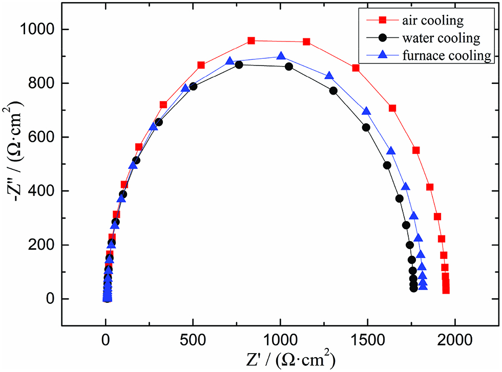
AC impedance spectroscopy of the samples.
Figure 3 shows a relationship curve of the average size and the average pitting potential. It was obvious that for the induced-pitting sensitivity of the whole sample, the sensitivity was changed with the average size of the sulfide inclusions in steel. The average pitting potential increased with the average size of MnS inclusions decreasing, and the sensitivity of pitting corrosion was decreased. However, when the average size of MnS inclusions was further decreased, the average pitting potential was decreased. It was demonstrated that there was a critical size to improve the pitting corrosion resistance in steel. When the size of MnS inclusions was less than the critical size, the pitting corrosion resistance was reduced instead. Ke and Alkire stated that when the size of MnS inclusions was larger than 0.7 μm, it would influence the pitting corrosion [17]. In the size range of this study, all of MnS inclusions would affect pitting corrosion and there was also a critical size in this range.

Relationship curve of the average size and the average pitting potential.
In order to further explore the relationship between the size of the MnS inclusions and the sensitivity of induced-pitting corrosion, the immersed samples were analyzed by SEM-EDS after polarization tests. And the images are shown in Figures 4–7.
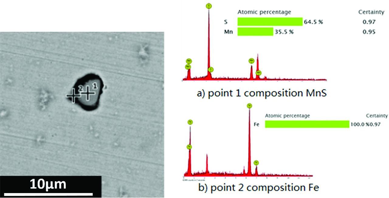
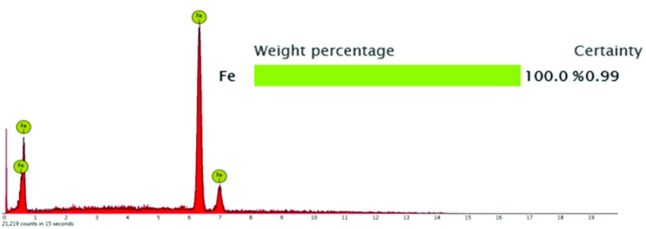
SEM and EDS results of typical MnS inclusion.
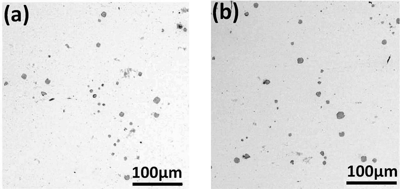
Low magnification SEM images of samples after corrosion.
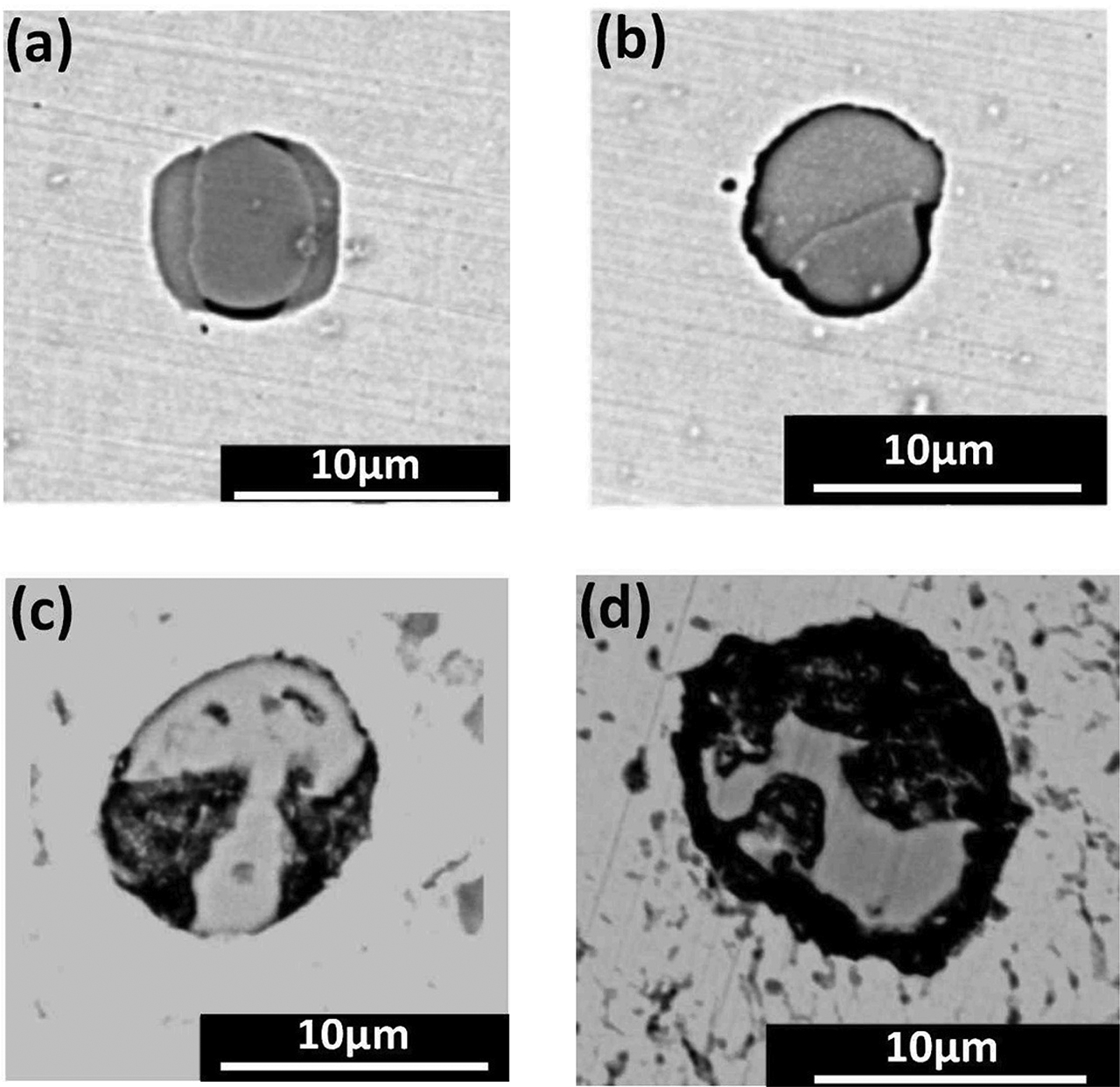
SEM images of four different pitting corrosion morphologies. (a) Sulfide inclusion surrounding matrix partly dissolved. (b) Sulfide inclusion surrounding matrix totally dissolved. (c) The interior of sulfide inclusion dissolved. (d) Both interior and surrounding matrix dissolved.

SEM images for different sizes of MnS inclusions.
Figure 4 showed the typical MnS inclusion morphology and composition analysis. Point 1 showed the component of MnS and point 2 is for Fe. The results indicated that MnS inclusion induced pitting corrosion and the micro cracks appeared around steel matrix. The black parts in the images were micro cracks because steel matrix was dissolved. Figure 5 shows SEM images which are under low magnification (700×). All of the MnS in the samples were observed and it was found that some MnS inclusions induced pitting corrosion but some did not. It meant that MnS inclusions inducing pitting corrosion was random.
Through statistically analyzing the observations, there were four different corrosion morphologies in MnS inducing pitting corrosion, as shown in Figure 6. (1) The steel matrix around MnS inclusions partly dissolved. (2) The steel matrix around MnS inclusions totally dissolved. (3) The inside of MnS inclusions dissolved. (4) Both the inside of MnS inclusions the steel matrix around MnS inclusions dissolved. At the same time, these different corrosion morphologies also demonstrated that inclusions inducing pitting corrosion presented the difference in time. Some inclusions begun to induce pitting and some inclusions have totally induced pitting. The occurrence of pitting was random.
Through analyzing the corrosion morphology from a multiple field of view, it can be found that the size of a single MnS inclusion had slight effect on inducing-pitting corrosion. However, a larger size of MnS inclusion could also cause steel matrix to dissolve more seriously. The reason for this phenomenon was that the dissolution rate of larger MnS inclusions had a faster dissolution rate forming bigger pit [18]. SEM images of different sizes of MnS inclusions are shown in Figure 7. Figure 7a showed that compared with the smaller size of MnS inclusions Ⅲ, the bigger size of MnS inclusion Ⅰ and Ⅱ both had a larger interfacial area with the steel matrix. And the steel matrix near the inclusions tended to dissolve seriously. Thus, the pitting potential of air-cooled samples was higher than that of furnace-cooled sample in the electrochemical test because the size of air-cooled sample was bigger than that of furnace-cooled sample. Figures 7b and 7c expressed that when the size of MnS was further reduced, the dissolution area of steel matrix was increased resulting in the rate of inducing-pitting increasing. It also found that if the number of clustered inclusions was increased, the relevance of inclusions was enhanced from the point view of distribution. As shown in Figures 7b and 7c, the pits caused by the inclusion Ⅰ and Ⅱ, respectively, were interrelated and formed a new bigger pit. And the dissolution of steel matrix was heavily. Thus, the pitting potential of water-cooled sample was reduced than that of air-cooled sample in the electrochemical test because the MnS inclusions in water-cooled sample were small and presented clustered in distribution. On the whole, for the small size of MnS inclusions, there were critical dimensions when the size of MnS inclusions had a critical value about improving the corrosion resistance of steel for smaller inclusions. And once the size was smaller than the critical value, the corrosion resistance of steel was decreased.
Corrosion immersion experiments and analysis
In order to study the effect of MnS inclusions on inducing-pitting corrosion, the experiment was conducted the corrosion immersion by FeCl3 solution for different times. And then the microscopic corrosion morphology was observed by SEM, as shown in Figure 8. The change of inclusion size was quantitatively analyzed by Image Pro Plus software.
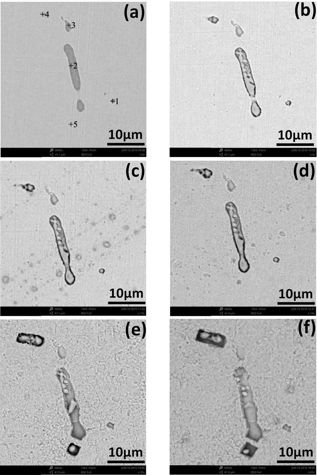
Different corrosion Morphology of MnS inclusions in different times. (a) 0 s; (b) 5 s; (c) 10 s; (d) 15 s; (e) 35 s; (f) 65 s.
As shown in Figure 8a, there were five points presenting in the figures. And five types of MnS inclusions were numbered 1, 2, 3, 4, and 5, respectively. The change of corrosion morphology of MnS inclusions could be summarized in the following five categories
For point 1: the type of inclusion was globular MnS inclusion, as shown in Figure 8a. Pitting corrosion occurred around the inclusions. And then a micro crack was formed between the steel matrix and the inclusion. As the corrosion time was going, the micro crack became further larger. And the steel matrix surrounding inclusion was totally dissolved. The inclusion was disappeared. When the corrosion time was 35 s, as shown in Figure 9, the results of EDS was only Fe element. It demonstrated that MnS was totally disappeared and micro pit formed on the steel matrix. The reason for the disappearance of MnS inclusion may be due to the complete dissolution of MnS inclusion or it may because the area of MnS being in contact with steel matrix was dissolved and the residual of MnS inclusion fell off into the corrosion solution. During further corrosion, the size of pit became bigger. On one hand, it may be caused by the corrosive dissolution product of MnS inclusion. On the other hand, it may be the effect of the micro cell caused by different concentration of the local environment.
Component analysis of point 1 at 35 s of corrosion.
For point 2: the MnS inclusion showed a long strip shape, and the bottom half of MnS was buried in the steel matrix, as shown in Figure 10 (black box). With the corrosion going, the micro cracks between the inclusions and the adjacent steel matrix became larger. And the interior of MnS inclusion and its surrounding steel matrix were gradually dissolved. However, the original inclusion buried in the steel matrix showed up gradually until all appeared. After corrosion for 35 s, as shown in Figure 8e, most of MnS inclusion disappeared. Only a small part of the MnS was residual in the long strip corrosion pit. The results of EDS are shown in Figure 11. The MnS inclusion began to fall off and the size of pit was increased.
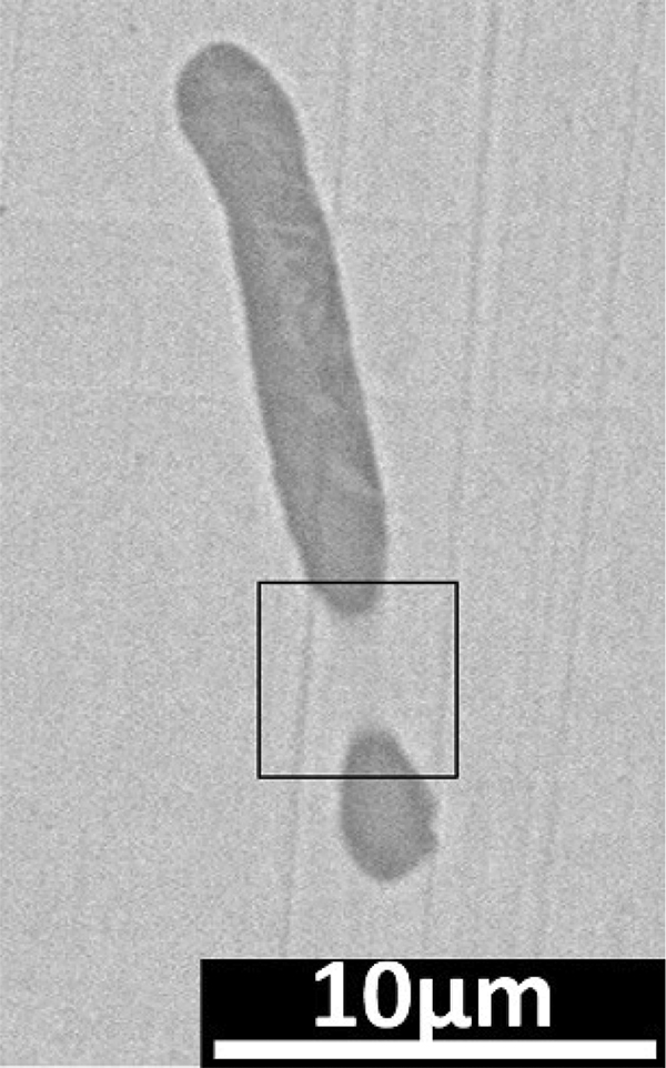
Point 2 microstructure before corrosion.

Composition analysis of point 2 at 35 s of corrosion.
For point 3: the shape of MnS inclusion was irregular, as shown in Figure 8a. With the corrosion going on, the inclusion gradually disappeared. And the size of pit was further larger. And with the uniform dissolution of steel matrix, the pit became shallow and finally became horizontal with surface of steel matrix.
For point 4: Most parts of the MnS inclusion were buried in the steel matrix. And only a little bit was on the surface, as shown in Figure 8a. With the corrosion going on, the MnS inclusion which was originally buried in the steel matrix showed up gradually. Both MnS inclusions and steel matrix had a tendency to dissolve. The micro crack between MnS inclusion and steel matrix grew bigger. After corrosion for 65 s, the rectangular pits with smooth edges formed. And in the internal of pits, it contained the residual MnS inclusions.
For point 5: there was no MnS inclusion presenting in this region, as shown in Figure 8a. After corrosion for 15 s, the MnS began to appear. And with further corrosion, a square pit with unsmooth edges appeared. After corrosion for 65 s, the size of pit became bigger and the edge of pit turned smooth. The size of inclusion was reduced due to its dissolution. According to the position variations of the residual inclusions in the figure, it can be inferred that the place between inclusion and steel matrix came to dissolve causing steel matrix falling off in the pit.
After corrosion for 65 s, the corrosion morphology of other field of view is shown in Figure 12. It can be observed that MnS inclusions which were shallowly buried in the steel matrix were readily to dissolve, fall off and form pit. And it can reduce the corrosion of steel matrix. However, if the MnS inclusions which were buried deeply in the steel matrix were difficult to dissolve, fall off and made the corrosion go deep into the steel matrix. Thus, it would result in a long-term influence on corrosion of steel matrix.

The corrosion morphology of the shallow MnS inclusions after 65 s of corrosion.
Analysis on induced-corrosion mechanism of MnS inclusions
The MnS inclusions in steel preferentially absorb Cl- related to steel matrix. And chloride ions could promote the dissolution of MnS making MnS more active and increasing the sensitivity of corrosion sensitivity [19]. In the process of induce-pitting corrosion, the dissolution of MnS included a chemical process and an electrochemical process [20]. The junction of the steel matrix and inclusions was the weakest point of the passive film. So, the junction was first corroded by Cl-. The surface of steel matrix was activated and the iron ion was first dissolved when inclusion induced pitting corrosion, as shown in Formula (1). And then the dissolved iron ion was hydrolyzed to produce H+, leading to local acidification, as shown in Formula (2). Next, the MnS inclusions dissolved, as shown in Formula (3). Finally, the dissolved MnS inclusions would generate HS-, H+ and HS- to erode surrounding steel matrix, which caused pitting corrosion happened and developed [21].
At the same time, the produced anodic current promoted MnS inclusions in electrochemical dissolution and produced precipitation of sulfur, as shown in Formula (4). In the absence of chloride ions, sulfur could also cause inclusions to induce pitting corrosion [22], indicating that sulfur has an erosion effect and exacerbated the corrosion.
Whether this process was chemical dissolution or electrochemical dissolution of MnS inclusions, its dissolution product was corrosive exacerbating the corrosion. The hydrolysis of iron ions and the dissolution of sulfide hindered the re-passivation film of fresh iron atom. And a small occluded zone was formed at the boundary between the inclusions and the steel matrix, which made corrosion develop along the boundary into steel matrix and formed bigger pit. And the corrosion mechanism diagram of MnS inclusions is shown in Figure 13.

MnS corrosion mechanism diagram.
Conclusions
In this study, the size of MnS inclusions was controlled by controlling different cooling. With the cooling rate increasing, the number of bigger size of inclusions reduced and the number of smaller size of inclusion increased. The results of electrochemical experiment showed that the sensitivity of air-cooled sample was the smallest and that of water-cooled sample was the biggest. And the sensitivity of furnaced-cooled sample is between the two. And there was a critical size of MnS inclusions to induce pitting corrosion. If the size of MnS was larger than critical size, the average pitting potential was increased with the decrease of the average size of MnS inclusions and the sensitivity of induced-pitting corrosion was reduced. And if the size of MnS inclusions was smaller than critical size, the average pitting potential was decreased with the decrease of the average size of MnS inclusions and the sensitivity of induced-pitting corrosion was increased.
The results of SEM-EDS elucidated that MnS inclusions pitting corrosion induced by MnS inclusions had randomness in space and time. And there were five pitting corrosion morphologies in the process of corrosion. And all pitting corrosion occurred around the MnS inclusions. The inclusions, and its surrounding steel matrix, were partially or totally dissolved. The clustered MnS had a higher sensitivity of inducing-pitting than a single MnS inclusion.
Corrosion immersion indicated that pitting corrosion also occurred around the MnS inclusions. And the micro cracks formed between the inclusions and adjacent steel matrix. And then both the inclusion and steel matrix dissolved forming pits. And the MnS inclusions which were buried deep in the steel matrix, were not easily to dissolve and fall off. The corrosion would penetrate deep into steel matrix causing greater damage. And the MnS inclusions which were buried shallowly in the steel matrix were readily to fall off in the steel matrix and caused less damage.
Acknowledgements
The authors are grateful for supported from the National Science Foundation of China (grant numbers 51574190 and 51674023).
References
[1] Q. Liu, S.F. Yang, M.J. Zhao, L.B. Zhu and J.S. Li, Metals, 7 (2017) 347–358.10.3390/met7090347Search in Google Scholar
[2] S.Q. Zheng, C.Y. Li, Y.M. Qi, L.Q. Chen and C.F. Chen, Corros. Sci., 67 (2013) 20–31.10.1016/j.corsci.2012.09.044Search in Google Scholar
[3] I.J. Park, S.M. Lee, M. Kang, S. Lee and Y.K. Lee, J. Alloys Compd., 619 (2015) 205–210.10.1016/j.jallcom.2014.08.243Search in Google Scholar
[4] C. Liu, R.I. Revilla, Z.Y. Liu, D.W. Zhang and X.G. Li, Corros. Sci., 129 (2017) 82–90.10.1016/j.corsci.2017.10.001Search in Google Scholar
[5] T.V. Shibaeva, V.K. Laurinavichyute, G.A. Tsirlina, A.M. Arsenkin and K.V. Grigorovich, Corros. Sci., 80 (2014) 299–308.10.1016/j.corsci.2013.11.038Search in Google Scholar
[6] R.E. Melchers, I.A. Chaves and R. Jeffrey, Metals, 6 (2016) 132–144.10.3390/met6060132Search in Google Scholar
[7] F.H. Duan, Res. Iron Steel, 44 (2016) 20–22.10.1016/S1006-706X(15)30102-3Search in Google Scholar
[8] D.E. Williams, M.R. Kilburn, J. Cliff and G.I.N. Waterhouse, Corros. Sci., 52 (2010) 3702–3716.10.1016/j.corsci.2010.07.021Search in Google Scholar
[9] I. Muto, D. Ito and N. Hara, J. Electrochem. Soc., 156 (2009) 55–61.10.1149/1.3033498Search in Google Scholar
[10] P. Schmuki, H. Hildebrand, A. Friedrich and S. Virtanen, Corros. Sci., 47 (2005) 1239–1250.10.1016/j.corsci.2004.05.023Search in Google Scholar
[11] N. Hara, K. Hirabayashi, Y. Sugawara and I. Muto, Int. J. Corros., 2012 (2012) 6pages.10.1155/2012/286174Search in Google Scholar
[12] X.J. Shao, X.H. Wang, W.J. Wang, C.W. Yang, F.X. Huang, M. Jiang and X.X. Deng, Trans. Mater. Heat Treat., 31 (2010) 80–84.Search in Google Scholar
[13] Y.J. Xia, F.M. Wang, J.L. Wang and J. Zhao, J. Univ. Sci. Technol. Beijing, 32 (2010) 1271–1276.Search in Google Scholar
[14] H.J. Wu, P.Y. Lu, F. Yue, L. Zhou, W.W. Chen and D.L. You, J. Univ. Sci. Technol. Beijing, 36 (2014) 230–234.Search in Google Scholar
[15] X.Z. Lu, R. Wu, S.L. Li, H.T. Wu, W.L. Zhai, L. Huang, D.B. Wu and S.P. Song, J. Wuhan Univ. Sci. Technol., 33 (2010) 147–150.Search in Google Scholar
[16] Z.Z. Liu, Y. Kobayashi, F.X. Yin, M. Kuwabara and K. Nagai, ISIJ Int., 47 (2007) 1781–1788.10.2355/isijinternational.47.1781Search in Google Scholar
[17] T.L.S.L. Wijesinghe and D.J. Blackwood, Corros. Sci., 49 (2007) 1755–1764.10.1016/j.corsci.2006.10.025Search in Google Scholar
[18] H. Krawiec, V. Vignal, O. Heintz, R. Oltra and J.M. Olive, J. Electrochem. Soc., 152 (2005) 213–219.10.1149/1.1924172Search in Google Scholar
[19] B. Vuillemin, X. Philippe, R. Oltra, V. Vignal, L. Coudreuse, L.C. Dufour and E. Finot, Corros. Sci., 45 (2003) 1143–1159.10.1016/S0010-938X(02)00222-6Search in Google Scholar
[20] L. Khaksar, J. Shirokoff, Mater., 10 (2017) 430–441.10.3390/ma10040430Search in Google Scholar PubMed PubMed Central
[21] J. Torkkeli, T. Saukkonen and H. Hänninen, Corros. Sci., 96 (2015) 14–22.10.1016/j.corsci.2015.03.002Search in Google Scholar
[22] Y.B. Li, J. Liu, Y.D. Deng, X.P. Han, W.B. Hu and C. Zhong, J. Alloys Compd., 673 (2016) 28–37.10.1016/j.jallcom.2016.02.224Search in Google Scholar
© 2018 Walter de Gruyter GmbH, Berlin/Boston
This article is distributed under the terms of the Creative Commons Attribution Non-Commercial License, which permits unrestricted non-commercial use, distribution, and reproduction in any medium, provided the original work is properly cited.
Articles in the same Issue
- Frontmatter
- Research Articles
- Numerical Simulation of the Electron Beam Welding and Post Welding Heat Treatment Coupling Process
- Effect of Ti and Ta on Oxidation Kinetic of Chromia Forming Ni-Base Superalloys in Ar-O2-Based Atmosphere
- Effects of Cerium on the Inclusions and Pitting Corrosion Behavior of 434 Ferritic Stainless Steel
- Critical Assessment of Activities of Structural Units in Fe–Al Binary Melts Based on the Atom and Molecule Coexistence Theory
- A Yield Stress Model for a Solution-Treated Ni-Based Superalloy during Plastic Deformation
- Stress Relaxation Behaviour and Creep Constitutive Equations of SA302Gr.C Low-Alloy Steel
- Effects of Inner Defects on Creep Damage and Crack Initiation for a Brazed Joint
- Experimental and Numerical Investigations on Hot Deformation Behavior and Processing Maps for ASS 304 and ASS 316
- Production of Iron Based Alloys from Mill Scale through Metallothermic Reduction
- Effect of Nb and V on Austenite Grain Growth Behavior of the Cr-Mo-V Steel for Brake Discs
- A Thermodynamic Study of the Reduction of a Limonitic Laterite Ore by Methane
- Electrochemical and Phase Analysis of Si(IV) on Fe Electrode in Molten NaCl-NaF-KCl-SiO2 System
- Characterization of Hot Deformation Behavior for Pure Aluminum Using 3D Processing Maps
- Effect of Chromium Addition on the Cyclic Oxidation Resistance of Pseudo-Binary (Mo,Cr)3 Si Silicide Alloy
- Equiaxed Solidification of 430 Ferritic Stainless Steel Nucleating on Core-Containing Ti
- FE Analysis of Dynamical Recrystallization during the Seamless Tube Extrusion of Semicontinuous Casting Magnesium Alloy and Experimental Verification
- Study on the Reblow Model for Medium-High Carbon Steel Melting by Converter
- Short Communication
- Effect of B2O3 on Slag-Metal Reaction between CaO-Al2O3-Based Mold Flux and High Aluminum Steel
- Review Article
- Computation of the Thermal Residual Stresses in SiC/SiC Composites with Multi-Layered Interphases by Using ANN with the Structure of Random Forest
- Research Articles
- Failure Analysis of the Corroded Water Wall Tube in a 50MW Thermal Power Plant
- CO2 Absorption of Powdered Ba2Fe2O5 with Different Particle Size
- Induced-Pitting Behaviors of MnS Inclusions in Steel