Laser marking as environment technology
-
Lydia Sobotova
 and
Miroslav Badida
and
Miroslav Badida

Abstract
The contribution deals with the laser marking as one of the progressive and environment friendly technologies with utilisation in many branches of industry. Engraving and other types of laser marking of different types of materials are very actual technologies these days. Laser marking decreases the waste creation in comparison with the other classical marking technologies, which use paintings or created chips. In this experimental investigation the laser marking surface texturing of material AL99,7 according to STN 42 4003:1993-08 (STN EN 573) has been conducted. The laser marking machine TruMark 6020 and software TruTops Mark were used. Laser surface texturing after laser marking has been realised under different combinations of process parameters: pulse frequency, pulse energy and laser beam scanning speed. The morphological characterization of engraving or annealing surfaces has been performed using scanning electron microscopy (SEM) technique. The evaluation of roughness of engraved surfaces has been realized according to STN EN ISO 4287 by using Surftest SJ 301. The aim of the contribution was to show how different laser parameters affect the surface texture and colour change of metallic materials while creating minimal waste.
1 Introduction
The laser technology is one of the progressive technologies, which enables towiden the utilization in various parts of production and industry. According to the information from the producers and users, the environmental safety conditions and waste minimization are diminishing in the world. They have become questions associated with the requirements for quicker production. The minimizations of the waste and permanent marking of products in the case of changes during the life-service or after damage of parts or during the identification of products are the important requirements of the producers and customers. Laser beam machining of processed materials has become a viable alternative to the conventional methods of machining of materials with changing properties such as strength, stiffness, toughness, resistance to corrosion and biological compatibility [1]. The laser marking is one of the possibilities to achieve these requirements. The contribution deals with the testing of material sheet AL99, 7 (STN 42 4003:1993-08) suitable for various ranges of forming applications. Laser marking results showed the possibility of the laser application to generate different surface structures for tribological modification of metallic materials and design too. Tested samples and structures were obtained by varying the processing conditions between surface engraving and surface re-melting. The evaluation of the achieved results of realized experiments has been realized by visual evaluation of obtained surfaces, roughness measuring and metallographic results. The microstructure and images of morphology of laser engraving tested samples have been expressed by using metallographic microscope Olympus and also illustrated by SEM microscope FEI QUANTA 400 with analyser EDAX. These experiments were prepared in cooperation with TRUMPF Slovakia, s.r.o.
2 Laser marking
Laser micromachining and laser marking processes are based on the interaction of electromagnetic radiation with a material. The mechanism of material removal includes different stages during this process: (a) melting, (b) vaporization and (c) chemical degradation. When a high energy density of laser beam is focused on the workpiece surface, the thermal energy is absorbed, which heats and transforms the work volume into molten, vaporized or chemically changed material that can be easily removed by flow of high pressure assist gas jet [2, 3]. There are many methods of part or product marking, including labels, ink systems, embossing, mechanical engraving, chemical and dry etching. During material marking with classical methods, many technological steps must be done, which are linked with energy consumption and waste occurring (e.g. tins with paints, worn tools, chips and chemicals) [4, 5]. Each marking method has its use, but laser marking is growing more and more popular and also becoming a very important tool for the development of rapidly growing micro - technology industry. The marking contrast can be achieved by the surface material removal or the colour change. When infrared lasers have been used, marking contrast relied on thermal effects. When UV lasers, such as excimer lasers have been used, marking contrast achieved through a photo-chemical transformation (i.e. colour change) [5, 6]. The utilisation of laser technology in metal processing is shown in Figure 1.
![Figure 1 Percentage of laser used technologies [8]](/document/doi/10.1515/eng-2017-0030/asset/graphic/j_eng-2017-0030_fig_001.jpg)
Percentage of laser used technologies [8]
Reversible interaction between the laser beam and the work-piece, product or tool forms the basis for each process. Figure 2 shows the interaction of laser radiation with the workpiece from various materials, where the incoming laser energy, reflection, absorption and transmission of laser beam into processed materials are shown [5, 6, 7, 8, 9].
![Figure 2 The absorption of material vs. wavelength [7]](/document/doi/10.1515/eng-2017-0030/asset/graphic/j_eng-2017-0030_fig_002.jpg)
The absorption of material vs. wavelength [7]
It is also important to understand, how the marked material absorbs laser light at the wavelength of the chosen laser. The absorptivity is the most important material parameter of the workpiece in laser-material interaction. For each configuration the absorptivity is given by the combination of laser parameters (i.e. wavelength, angle of incidence and polarization of the laser radiation) and the material radiative properties, state, geometry of the surface and temperature. A higher value of the resulting absorptivity means that more laser radiation is used for the processing [6]. Ferrous and non-ferrous materials have excellent absorption at 1064 nm, while precious metals do so at 355 and 532 nm [7]. The surface finishing and the coating of the workpiece also affect the absorptivity. Bare metal surface will be difficult to be marked by CO2 lasers, but it can be easily marked by Nd:YAG or excimer lasers.
Laser marking of materials [5, 6] uses various marking methods as shown in Table 1.

In engraving, the laser beam removes part of the parent material. The mark is visible as a depression [5].
In ablation, the laser removes a coating layer. The underlying base material is visible in the mark [5].
In annealing and colour change processes, the laser heats the workpiece, altering the colour. The surface remains smooth [5].
In foaming, reactions in the plastic material produce gas bubbles, which form a raised, or textured, mark [5].
When selecting a laser marking system for a particular application, there are many factors to consider [9]:
power density,
thermal: thermal conductivity, heat capacity, melting point and heat of vaporisation,
reflectivity: material, wavelength and temperature.
In the marking process, the used energy density is often high enough that the desired vaporization completes in microseconds. A series of vaporized craters in a surface usually alters its appearance. The marking contrast depends on the chemistry of the material, the surface finishing and the colour. A good mark edge resolution is achievable. The mark depth and the width are controllable. Materials such as plastic, glass, ceramic, rubber and metals will be slightly engraved with a distinct change of the surface structure [9].
3 Experimental research, method, set up and discussion
The experimental method and testing of the marked material samples were prepared in the laboratories of Technical University of Kosice, Faculty of Mechanical Engineering, the Department of Process and Environmental Engineering and in Trumpf Slovakia, s.r.o.
The laser machine parameters are shown in Table 2.
Technical parameters of TruMark 6020
| solid-state crystal | Nd: YAG |
| mode of work | pulse |
| wavelength | 1064 nm |
| pulse repetition frequency | 1-120 kHz |
| min. focal diameter | 42/45 μm |
| max. marking field size | 120x120 mm |
| max. power | 20 KW |
| calibre accuracy - scanner | ± 50 μm |
| max. power consumption | 230 V; 115 V |
| frequency consumption | 50, Hz; 60 Hz |
We used the laser marking machine TruMark 6020 and software TruTops Mark for the testing of the chosen material at various technological parameters.
During the experiment Trumpf navigator system was used, which served for the right laser setting for the tested materials. Figure 3 shows the navigator tested engraved matrix fields. In each testing field various testing parameters were chosen.

The example of the engraved samples: 1 - pulse frequency, 2 - speed engraving, 3 - description of the field, 4 - number of repetitions
During the laser marking, the pattern of engraving determines:
the overlap of runs and lines (visible under the microscope),
the angle of the incident beam: 90° degrees,
the number of repetitions - determined number of times the laser beam passes over a given quadrant,
the sample lines pitch 0.03 mm (Figure 4),
the rotation angle of 17 degrees of the next repetition (Figure 5).

Line pitch at laser marking
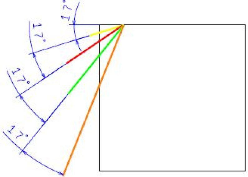
Rotating angle of laser beam
In the research experiment, we used material AL 99,7 according to STN 42 4003:1993-08 (STN EN 573), the mechanical properties and the chemical properties of which are shown in Table 3 and Table 4 respectively.
Mechanical properties of tested material – Al 99,7
| Description of material | Cross section [mm2] | Rm [MPa] | Elongation A10 [%] | Hardness Brinell HB |
|---|---|---|---|---|
| 42 4003 | 0,2 to 10 | max. 90 | 25 | 17-23 |
Chemical properties of tested material – Al 99,7 [%]
| Description of material | Al | Admixtures |
|---|---|---|
| 42 4003 | min 99,7 | 0,015 Cu / 0,16 Fe / 0,16 Si / 0,1 others |
The shape and the dimension of testing samples are shown in Figure 6.

Samples: A-The sample for engraving with geometrical parameters, B - example of the real sample from aluminium
In the experiment the laser beam ran through the tested material according the navigator and created the testing fields (Figure 7). The first evaluation of the surface quality and the colour change of the tested material was done visually and by using USB microscope. The colour and surface qualities of the tested fields were varying and dependent on the technological parameters. We chose the most contrasting fields with the different colours from the tested samples (the darkest one and the lightest one) for the next microscope evaluation.

The tested sample according to the navigator with changed laser beam parameters
In practice, when the parts must be marked for control or for evidence, it is necessary to make and create contrast labelling of products.
We used the USB microscope for quick and better macro view evaluations. The colour of the marked surfaces changed from silver through grey to black, depending on the laser parameter changes (Figure 8 and Figure 9).

Visually chosen experimental samples, fields A0, A3, A7
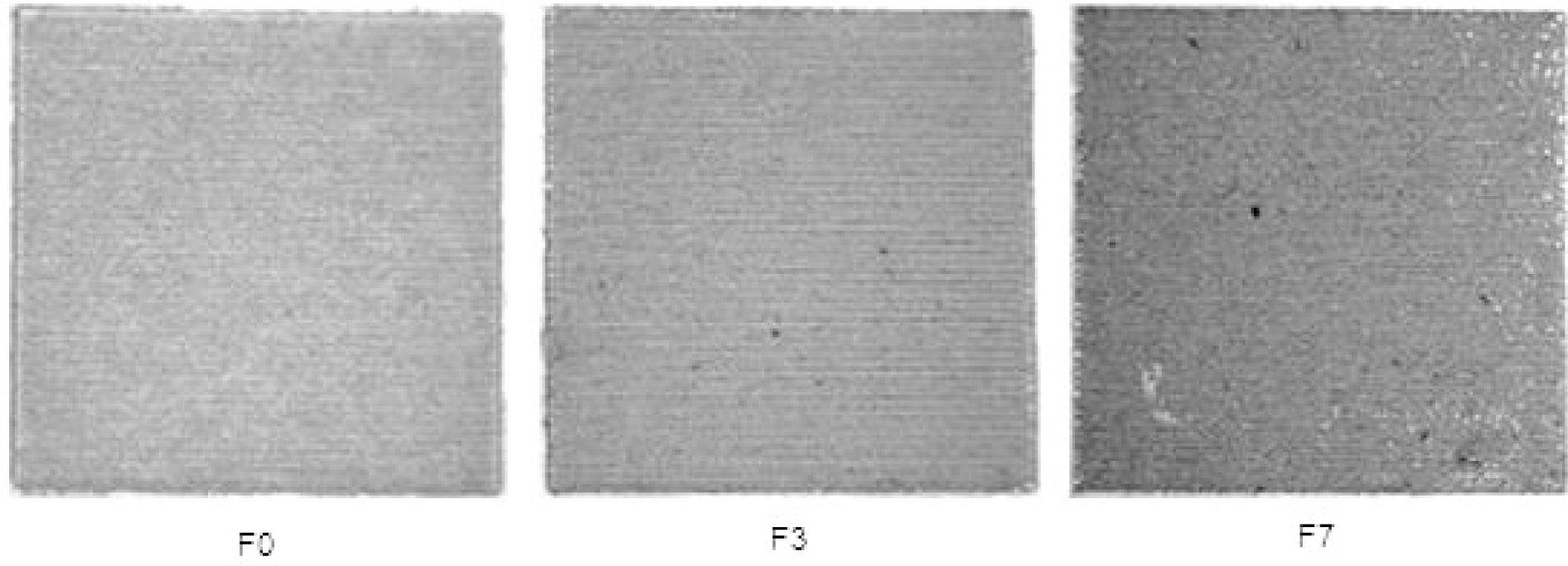
Visually chosen experimental samples, fields F0, F3, F7
From the point of view of surface microgeometry, the surfaces are classified as oriented and non-oriented [9].
The surfaces of the tested fields, where the laser beam processed the material, can be divided into:
re-melted oriented surfaces with created lines (the laser beam cross the surface only once) after laser marking with lower speed of laser beam,
re-melted non-oriented surfaces with crossing of laser beam through the surface more than once.
Figure 8 shows three types of testing fields with various parameters, according to the navigator. The surface of the field A0 is non-oriented, but the fields A3 and A7 started to show very fine oriented lines.
Figure 9 (surfaces of the fields A0, A3, A7) shows oriented fields. The lines with laser beam tracks are visible without any problem.
The microscope OLYMPUS was used next for more detailed evaluation of the surface. The microstructures of marked material from the fields (A0, A3, A7) are shown in Figure 10, Figure 11 and Figure 12. During the processing of the fields A0, A3, A7, the stabile marking parameters: speed 20 mm/s and frequencies 10, 40 and 80 kHz were used.

Microstructure of Al 99,7 material, field A0, non-oriented surface

Microstructure of Al 99,7 material, field A3, oriented surface

Microstructure of Al 99,7 material, field A7, oriented surface
In the field A3 (Figure 11), the line spacing at the frequency 40 kHz is seen. According to visual evaluation, significant line spacing is seen in the field A7 at the frequency of 80 kHz, which is the maximal frequency value for the Al material.
The surface of field A0 is non-oriented and melted with evaporated locations. The fields of A3 and A7 have oriented surfaces.
Figure 13, Figure 14 and Figure 15 show the microstructures from the testing fields F0, F3 and F7. During the processing of fields F0, F3 and F7, the stabile speed of marking was 220 mm/s and the frequencies were 10, 40 and 80 kHz. In field F0, - line spacing at pulse frequency 10 kHz is seen, which was not seen in field A0. According to visual evaluation, in field F3 significant line spacing is seen after laser marking and in field F7 the fusion of Al material started, material - melted and the line spacing was not so significant at the frequency of 80 kHz. In Figure 14, the best lines in the material surface in the tested fields were reached.

Microstructure of AL 99,7 material, field F0

Microstructure of AL 99,7 material, field F3, oriented surface

Microstructure of AL 99,7 material, field F7
In Figure 16 the microstructure after rotation of laser beam is seen and the changed angle in the navigator is as shown in Figure 5. The laser beam crossed the material four times. The surface layer became re-melted and non-oriented.

The example of microstructure after rotation of laser beam
For more detailed evaluation of the tested results, we investigated the tested laser marked samples also by the SEM microscope FEI QUANTA 400 with analyser EDAX. The SEM analyses of chosen tested fields are shown in Figure 17 to Figure 22.

SEM microstructure, field A0

The cross section of the tested field A0 on the left side

The cross section of the tested field A0 on the right side

SEM microstructure, Field F7

The cross section of the tested field F7 on the left side

The cross section of the tested field F7 on the right side
Figure 17 shows the SEM microstructure of the tested field A0. The surface of the tested sample after laser marking is non-oriented. In the tested field we can see the evaporated locations and the surface tops, which are not in one layer. The surface is pleated.
The chemical composition of material Al 99,7 from field A0 is shown in Table 5.
Field A0 - SEM results
 |
The cross section of the tested sample, field A0, left side, is shown in Figure 18. The border on the left side between the original, non-processed surface and the laser marked surface is observable. Between each laser beam marked lines the depths of craters can be seen with depth values around 136,1 μm. The depth and the shape of the lines are nearly the same. The projections are compact and in the interspaces residual oxides are visible.
The cross section of the tested sample, field A0, right side, is shown in Figure 19. We can see various depths of the marked sample. The measured depth at the border is 176,4 μm. The original surface of the tested field A0 is without defects and on the right side. In the interspaces residual oxides are visible. In Figure 19 it is seen that, during the starting of laser marking, the occurrence of deeper lines are created, which is dependent on the starting and burn of the laser beam.
Figure 20 show the microstructure of tested field F7. The surface of the tested sample after laser marking is oriented. We can see the lines after crossing of the laser beam. The lines are repeated at the same distance which is important for marking, to obtain homogeneous and similar surfaces, with the same colour of the marked field.
The chemical composition of material Al 99,7 from field F7 is shown in Table 6.
Field F7 - SEM results
 |
The cross section of the tested sample, field F7 (left side) is shown in Figure 21. The border between original surface and laser marked surface is clear. Between each laser beam marked lines, various depths can be seen with values around 50,3 μm. The projections are compact and the interspaces are shallow and the residual oxides are visible in the interspaces, too.
With the changing of the laser parameters of the tested field F7, the distance between the lines of the tested sample are nearly the same except at the beginning of the marking. The shape of the lines is changed. They are not so deep, but are wider as in the fields A7. The small deviations of the shape occurred at the starting of the marking process.
The cross section of the tested sample, field F7, right side, is shown in the Figure 22. We can see the various depths of the marked sample. The measured depth at the border is 42,4 μm. The original surface of the tested field F7 is without defects and on the right side. In the interspaces residual oxides are visible.
The surface microgeometry is dependent on the marked material properties and the technological parameters of laser.
Regarding a specific character of microgeometry of marked surfaces the most suitable and elaborated is the evaluation of surface structure by profile-method using a contact profile-meter. For the evaluation of roughness of laser marked surfaces the quantities normalized in STN EN ISO 4287 were used. As the chosen measured parameters, Ra (arithmetical mean deviation of the profile on the sampling length, as the most frequently used quantity) and Rz (maximum height of profile on the sampling length, as the second roughness parameter) were used.
The roughness evaluation was carried out in accordance with STN EN ISO 4287 using Surftest SJ-201. Settings for roughness measurement were-measured profile: Ra, filter: GAUSS, sampling length l (λc): 0,25 mm, number of sampling lengths: N = 5 and number of measured profiles:13. The changes of the surface character can be seen from the profiles measured on material Al 99, 7 in Table 7 and Table 8.
Profiles of material Al 99,7, testing fields A
 |
Profiles of material Al 99,7, testing fields F
 |
The values of micro-hardness of Al 99,7 material, measured by micro-hardness machine HMV-2, were changed in relation to the testing field. The greatest value of micro-hardness 106, 85 was measured in the sample field A0. After changing the laser parameters in the fields A0, A3 and A7, the micro-hardness values decreased from 106, 85 to 50,3.
4 Conclusion
From laser marking methods, the laser micro machining and laser marking are the best and the mostly applied techniques nowadays to create permanent marks on a wide range of materials and that is why we used them in our research. We realized experimental works on a set of test samples. The test results with different surface morphology can serve to widen the information in the parameter databases of laser marking of materials.
From the experimental results of material marking tests with various laser parameters, we chose different laser parameters and made the conclusions:
During the visual evaluation of colour scale of engraved surface of Al samples, we found that, with the increase of the pulse frequency and speed, the colour of engraving square passes to a lighter colour shade. The colour scale was changed from silver to black colours depending on the technological parameters. The USB microscope can be used for quick evaluation of surface and colour.
When we observed the microstructure of material AL 99,7 by the microscope OLYMPUS, we found that with the increase of pulse frequency and speed, oriented structure – lines were observed in the aluminium samples after engraving. The quality of lines – oriented surface, melted or non-oriented surface depends on the laser beam parameters. It is suitable to make - samplers of tested materials.
The depth of tested engraved surface (created lines) changes depending on the laser beam parameters, but during onsetting, the surface (shape, depth and width) keeps nearly the same dimensions and quality.
We measured the roughness of the originally tested sample and the roughness of tested fields and the characteristics of roughness profiles werechanging with laser parameters, but in the same field, the roughness profile had nearly the same course except at the beginning of the first line after laser marking of the material.
We checked the state at the borders of the tested fields (transition from the original surface to the laser marking surface), as it can be seen in Figure 21 and Figure 22.The quality is satisfactory, without specific melting or burning at the borders. Also it can be seen in the sample in Figure 7 with various testing fields.
When the number of laser runs across the tested fields increased (from 2 to 10 times), we observed larger thermal effect caused by re-melting of the surface structure.
SEM microscope FEI QUANTA 400 with analyser EDAX were used for detailed visualisation of tested samples, where we confirmed that, by maintaining the settings of laser parameters, the surface quality in a setting does not change and has the same characteristics.
From the environmental point of view, we confirm that the advantages of the laser marking are as follows:
Laser engraving technology is environmentally friendly from the view of waste creation. Minimum waste is produced during the operation. There are no chips or lubrications as in the classical machining. In comparison with spraying, laser marking does not need paints and other required media.
Laser graving operation terms very short time and can be done on various shapes and surfaces of workpieces.
The influence on the working environment is minimal, because the operations are usually carried out in closed cabins with dust extraction by filters and pumps.
The thermal influence of laser machine and noise influence areminimal as the working space is enclosed.
Laser marking machines consume less electrical energy (e.g. only 0,45 KWh) in comparison with cutting or welding, where the requirement is from 10 to 16 KWh.
After right set up, there is guarantee on the repeatability of technology process. It can also be automated, which also reduce the errors and waste production.
The disadvantage we see are in:
the price and service of the laser machines for small enterprises,
training of staff - there is necessity for learned and specialized workers,
the working environment must be protected, because of the creation of burned surfaces of parts.
The engraving laser method belongs to the new technology, which is used for describing different types of materials. The major advantages of this technology include : a description of permanent good quality, non-contact process (no tools required), minimal-waste treatment; no need for clamped workpieces, low operating costs and business process.
With simple programming the descriptions of serial numbers, texts, barcodes, matrix codes, logos, brands and various symbols can be done.
Acknowledgement
This work was supported by the projects of the Ministry of Education, Science, Research and Sport of the Slovak Republic KEGA 048TUKE-4/2015 and VEGA 1/0537/15.
References
[1] Brandt M., Sun S., Laser beam machining, Non-traditional machining process, London, Springer, 2013Search in Google Scholar
[2] Mishra S., Yadava V., Laser beam micromachining (LBMM) - a review, Optics and Lasers in Engineering, 2015, 73, 89-12210.1016/j.optlaseng.2015.03.017Search in Google Scholar
[3] Sugar P., Sugarova J., Frncik M., Laser surface texturing of tool steel: textured surfaces quality evaluation, Open Eng., 2016, 6, 90-9710.1515/eng-2016-0012Search in Google Scholar
[4] Kralikova R., Badida M., Environmentálne merania a monitoring v strojárstve (Environmental measuring and monitoring in Manufacturing), 1st.ed., Reprocentrum, Košice, 2010Search in Google Scholar
[5] Buchfink, G., The laser as a tool, 1st.ed, Rosler Druck GmbH, Schondorf, 2007,Search in Google Scholar
[6] Trumpf Slovakia, s.r.o., Engraving of materials, 2015, www.sk.trumpf.comSearch in Google Scholar
[7] Kaminski D., Laser Marking. How to choose the best laser for your marking application, Laserfocusworld 2011, http://www.laserfocusworld.com/articles/2011/04/laser-marking-how-to-choose-the-best-laser-for-your-marking-application.htmlSearch in Google Scholar
[8] Han, A., Gubencu, D., Analysis of the Laser Marking Technologies, Nonconventional Technologies Review, 2008, http://www.revtn.ro/pdf4-2008/4-Han_A.pdfSearch in Google Scholar
[9] Sobotova L., Demec P., Laser marking of metal materials, MM Science Journal, 2015, 808-81210.17973/MMSJ.2015_12_201410Search in Google Scholar
[10] Draganovska D., Izarikova G. et al, Modification of surface morphology of Ti6Al4V alloy manufactured by laser sintering, Open Eng., 2016, 6, 164-17310.1515/eng-2016-0020Search in Google Scholar
[11] Drotar, A., Duska, J., Hrabcakova, L., Kalmar, P., Maslejova, A., Metallographic Investigation of Failed Wheel Rim Weld Joints, 16-th International Symposium on Metallography and Materials Science, 2016, Trans Tech Publ. Ltd, Switzerland, 2016, 28810.4028/www.scientific.net/MSF.891.288Search in Google Scholar
© 2017 L. Sobotova and M. Badida
This work is licensed under the Creative Commons Attribution-NonCommercial-NoDerivatives 4.0 License.
Articles in the same Issue
- Regular Articles
- The Differential Pressure Signal De-noised by Domain Transform Combined with Wavelet Threshold
- Regular Articles
- Robot-operated quality control station based on the UTT method
- Regular Articles
- Regression Models and Fuzzy Logic Prediction of TBM Penetration Rate
- Regular Articles
- Numerical study of chemically reacting unsteady Casson fluid flow past a stretching surface with cross diffusion and thermal radiation
- Regular Articles
- Experimental comparison between R409A and R437A performance in a heat pump unit
- Regular Articles
- Rapid prediction of damage on a struck ship accounting for side impact scenario models
- Regular Articles
- Implementation of Non-Destructive Evaluation and Process Monitoring in DLP-based Additive Manufacturing
- Regular Articles
- Air purification in industrial plants producing automotive rubber components in terms of energy efficiency
- Regular Articles
- On cyclic yield strength in definition of limits for characterisation of fatigue and creep behaviour
- Regular Articles
- Development of an operation strategy for hydrogen production using solar PV energy based on fluid dynamic aspects
- Regular Articles
- An exponential-related function for decision-making in engineering and management
- Regular Articles
- Usability Prediction & Ranking of SDLC Models Using Fuzzy Hierarchical Usability Model
- Regular Articles
- Exact Soliton and Kink Solutions for New (3+1)-Dimensional Nonlinear Modified Equations of Wave Propagation
- Regular Articles
- Entropy generation analysis and effects of slip conditions on micropolar fluid flow due to a rotating disk
- Regular Articles
- Application of the mode-shape expansion based on model order reduction methods to a composite structure
- Regular Articles
- A Combinatory Index based Optimal Reallocation of Generators in the presence of SVC using Krill Herd Algorithm
- Regular Articles
- Quality assessment of compost prepared with municipal solid waste
- Regular Articles
- Influence of polymer fibers on rheological properties of cement mortars
- Regular Articles
- Degradation of flood embankments – Results of observation of the destruction mechanism and comparison with a numerical model
- Regular Articles
- Mechanical Design of Innovative Electromagnetic Linear Actuators for Marine Applications
- Regular Articles
- Influence of addition of calcium sulfate dihydrate on drying of autoclaved aerated concrete
- Regular Articles
- Analysis of Microstrip Line Fed Patch Antenna for Wireless Communications
- Regular Articles
- PEMFC for aeronautic applications: A review on the durability aspects
- Regular Articles
- Laser marking as environment technology
- Regular Articles
- Influence of grain size distribution on dynamic shear modulus of sands
- Regular Articles
- Field evaluation of reflective insulation in south east Asia
- Regular Articles
- Effects of different production technologies on mechanical and metallurgical properties of precious metal denture alloys
- Regular Articles
- Mathematical description of tooth flank surface of globoidal worm gear with straight axial tooth profile
- Regular Articles
- Earth-based construction material field tests characterization in the Alto Douro Wine Region
- Regular Articles
- Experimental and Mathematical Modeling for Prediction of Tool Wear on the Machining of Aluminium 6061 Alloy by High Speed Steel Tools
- Special Issue on Current Topics, Trends and Applications in Logistics
- 10.1515/eng-2017-0001
- Special Issue on Current Topics, Trends and Applications in Logistics
- The Methodology of Selecting the Transport Mode for Companies on the Slovak Transport Market
- Special Issue on Current Topics, Trends and Applications in Logistics
- Determinants of Distribution Logistics in the Construction Industry
- Special Issue on Current Topics, Trends and Applications in Logistics
- Management of Customer Service in Terms of Logistics Information Systems
- Special Issue on Current Topics, Trends and Applications in Logistics
- The Use of Simulation Models in Solving the Problems of Merging two Plants of the Company
- Special Issue on Current Topics, Trends and Applications in Logistics
- Applying the Heuristic to the Risk Assessment within the Automotive Industry Supply Chain
- Special Issue on Current Topics, Trends and Applications in Logistics
- Modeling the Supply Process Using the Application of Selected Methods of Operational Analysis
- Special Issue on Current Topics, Trends and Applications in Logistics
- Possibilities of Using Transport Terminals in South Bohemian Region
- Special Issue on Current Topics, Trends and Applications in Logistics
- Comparison of the Temperature Conditions in the Transport of Perishable Foodstuff
- Special Issue on Current Topics, Trends and Applications in Logistics
- E-commerce and its Impact on Logistics Requirements
- Topical Issue Modern Manufacturing Technologies
- Wear-dependent specific coefficients in a mechanistic model for turning of nickel-based superalloy with ceramic tools
- Topical Issue Modern Manufacturing Technologies
- Effects of cutting parameters on machinability characteristics of Ni-based superalloys: a review
- Topical Issue Desktop Grids for High Performance Computing
- Task Scheduling in Desktop Grids: Open Problems
- Topical Issue Desktop Grids for High Performance Computing
- A Volunteer Computing Project for Solving Geoacoustic Inversion Problems
- Topical Issue Desktop Grids for High Performance Computing
- Improving “tail” computations in a BOINC-based Desktop Grid
- Topical Issue Desktop Grids for High Performance Computing
- LHC@Home: a BOINC-based volunteer computing infrastructure for physics studies at CERN
- Topical Issue Desktop Grids for High Performance Computing
- Comparison of Decisions Quality of Heuristic Methods with Limited Depth-First Search Techniques in the Graph Shortest Path Problem
- Topical Issue Desktop Grids for High Performance Computing
- Using Volunteer Computing to Study Some Features of Diagonal Latin Squares
- Topical Issue on Mathematical Modelling in Applied Sciences, II
- A polynomial algorithm for packing unit squares in a hypograph of a piecewise linear function
- Topical Issue on Mathematical Modelling in Applied Sciences, II
- Numerical Validation of Chemical Compositional Model for Wettability Alteration Processes
- Topical Issue on Mathematical Modelling in Applied Sciences, II
- Innovative intelligent technology of distance learning for visually impaired people
- Topical Issue on Mathematical Modelling in Applied Sciences, II
- Implementation and verification of global optimization benchmark problems
- Topical Issue on Mathematical Modelling in Applied Sciences, II
- On a program manifold’s stability of one contour automatic control systems
- Topical Issue on Mathematical Modelling in Applied Sciences, II
- Multi-agent grid system Agent-GRID with dynamic load balancing of cluster nodes