High tribo-corrosion resistance of Ni-Cr-5Al2O3 thermal spray coating: a comparison of post processing techniques
-
Mayank Garg

 ,
Harpreet Singh Grewal
,
Harpreet Singh Grewal

Abstract
Engineering materials are known to show degradation in terms of tribo-corrosion characteristics in marine environment. The concurrent increase in erosion and corrosion resistance can make them more appealing for structural applications. The thermal spray coatings are typically used to mitigate the degradation of structural components. Although, the microstructure of as-sprayed coating indicates inconsistency in the form of distinct splats and elemental segregation. Furnace annealing, microwave processing and stationary friction processing (SFP) are performed to improve the non-homogeneous microstructure of the thermal spray coating. SFP has several attractive properties to refine the grain structure and reducing the defects density on the surface. Therefore, SFP has been explored as a surface modification technique for thermal spray coating with an aim to enhance the performance of the processed coating. Slurry erosion and erosion corrosion tests are conducted on as-sprayed and processed coatings at normal and oblique impingement angle. Erosion rate of SFPed specimen is comparatively lower than that of the as-sprayed, furnace annealed and microwave processed specimens in both slurry erosion and erosion corrosion. Furthermore, the SFPed coating indicated least corrosion rate as compare to furnace annealed, microwave coating and as-sprayed coating.
Abbreviations
- AS
-
as-sprayed
- BSE
-
back scattered electron
- EDS
-
energy dispersive X-ray spectroscopy
- EEC
-
equivalent electrical circuit
- FA
-
furnace annealing
- FA11
-
specimen annealed at 900 °C for 5 min
- FA12
-
specimen annealed at 900 °C for 15 min
- FA21
-
specimen annealed at 1,100 °C for 5 min
- FA22
-
specimen annealed at 1,100 °C for 15 min
- FESEM
-
field emission scanning electron microscopy
- HVOF
-
high velocity oxy-fuel
- MWP
-
microwave processing
- OCP
-
open circuit potential
- SCE
-
saturated calomel electrode
- SFP
-
stationary friction processing
- TSC
-
thermal spray coating
- XRD
-
X-ray diffraction
1 Introduction
Functioning of materials, which are interacting continuously with the flowing fluid, is of fundamental importance to many sectors of industries including offshore, marine, power generation, gas production, petrochemical, automobiles, materials production and processing etc. Typically, the component life in all these sectors reduces if they are exposed to harsh working conditions, like fluid containing some sort of abrasive and salt content, owing to the effects of mechanical erosion and electrochemical corrosion mechanisms. The ability of materials to withstand in marine environments, comprising of high concentration of slurry and salt, is of prime concern for industrial sustainability. Therefore, improving the surface properties of materials, either by altering its microstructure or by depositing a coating which are responsible for delaying the onset of part failure, is imperative. However, the use of hard, wear resistant and corrosion resistant coatings developed using thermal spraying is considered as the plausible strategy for the same. This is due to the high adaptability of coating recipes, inexpensive and convenient to use.
The erosion and corrosion behavior of TSCs has been extensively reported (Cho et al. 2006; Matthews et al. 2007; Mehta et al. 2017; Nicholls et al. 1999; Toma et al. 2001). Liu et al. (2016) examined the effect of rare earth 1 % CeO2 on the erosion and corrosion behavior of high velocity oxy-fuel (HVOF) WC-12Co coatings. Addition of CeO2 as a dopant considerably reduces the erosion and corrosion rates for the HVOF coatings. Kumar Goyal et al. (2012) investigated the slurry erosion behavior of HVOF sprayed WC-10Co-4Cr and Al2O3-13TiO2 coating on a turbine steel. HVOF WC-10Co-4Cr coating was found to be useful to enhance the slurry erosion resistance of the steel as compared to Al2O3-13TiO2 HVOF coating owing to the higher hardness of the WC-10Co-4Cr coating. Santa et al. (2009) studied the effect of four types of coatings including Ni-1(Ni95 % Al5 %), Ni-2 (cladded Ni, Cr, Mo, Ti), WC/Co–Ni (WC/Co 46 % – NiFeCr 54 %) and Cr (Cr2O3) TSCs to probe their slurry erosion resistance and found that WC/Co-Ni TSC is performing best in slurry erosion conditions as compared to other coatings. Guilemany et al. (2006) reported a comparative wear and corrosion properties of Cr3C2-NiCr HVOF and hard chromium (HC) coating. HVOF coating showed a better friction wear behavior and corrosion resistance than HC coatings. Wang and Lee (2000) probed the erosion-corrosion behavior of HVOF NiAl-Al2O3 intermetallic-ceramic coating. Four different compositions namely 30Al2O3–70NiAl, 75Cr3C2/TiC-25NiCrMoAl, 75Cr3C2-25NiCr and Fe-25Cr-3B-2Si were investigated and found that 30Al2O3-70NiAl exhibits highest erosion and corrosion resistance along with excellent thermal shock resistance. Thus, it has been realized that TSCs containing hard phase dispersed in NiCr rich matrix are widely used for erosion and corrosion resistance applications.
Since, the preventive capabilities of the thermal spray coatings (TSCs) are constrained by their intrinsic non-homogeneous morphology. The presence of pores, splats, elemental segregation and partially melted particulates in TSCs undermines the performance in terms of erosion and corrosion and reduces the interfacial adhesion between the coating and substrate. Therefore, it is important to remove/reduce these detrimental entities with the application of post processing techniques like heat treatment (Dong et al. 2017; Qin et al. 2020; Zhao et al. 2011), laser processing (Škamat et al. 2019; Škamat et al. 2021), microwave sintering (Chen et al. 2019; Iizuka et al. 2022) and thermoplastic deformation (Arora et al. 2020a,b,c).
In the present study, NiCr-5 % Al2O3 TSCs have been developed and processed through three different processing routes namely furnace annealing, microwave sintering and stationary friction processing (SFP). Furnace annealing significantly reduces the area porosities by eliminating the network of interconnected pores on the expense of oxidation and mechanical property degradation owing to grain coarsening (Bergant et al. 2014). In microwave sintering, the coating is exposed to molecular level heating resulting in a small processing time and steep heating rate. The removal of splats and pores as a result of homogeneous heating mends the microstructural and mechanical characteristics of the TSCs (Nair et al. 2019). During SFP, a severe thermoplastic deformation technique, the TSC is kept under the action of high strain rates and thermal field leading to significant refinement in the coating microstructure within a short span of time. SFP resulted in significant enhancement in the deprivation resistance, surpassing the effects of microwave sintering and furnace annealing. Comprehensive microstructural refinement of the TSC up to the interface favors the explanation of the obtained results.
2 Materials and methods
Substrate was a plate made of stainless steel of grade 316L (nominal composition is shown in Supplementary Table S1) with dimension of 150 × 100 × 1.5 mm3 and grit blasted with brown corundum powder at a pressure of 4 bar before deposition in order to increase adhesion between the coating/substrate interface. Micro-powders (Sigma Aldrich, 99.5 % pure) of Ni, Cr and Al2O3 were intermixed in a required proportion of 47.5, 47.5 and 5, respectively. Ni-Cr-5Al2O3 coatings were deposited by using a commercial high velocity oxy fuel (HVOF, HIPOJET-2700) spray system. The coating specimens were sectioned into the dimension of 15 × 10 × 2.5 mm3 and homogenized using three different processing routes: (a) furnace annealing (FA), (b) microwave processing (MWP) and (c) stationary friction processing (SFP).
2.1 Post processing techniques
2.1.1 Furnace annealing
Sectioned specimen was utilized for the short-term furnace annealing in a high temperature tubular furnace equipped with an external vacuum unit and Ar gas supply. The specimen was kept in an alumina boat and placed inside the cavity of tubular furnace. The furnace annealing of the specimen was performed at temperature 900 °C and 1,100 °C in an argon environment for a duration of 5 min and 15 min. The rate of heating of the furnace was kept at 10 °C/min. A schematic depicting the furnace annealing of the coating specimens is shown in Figure 1a.
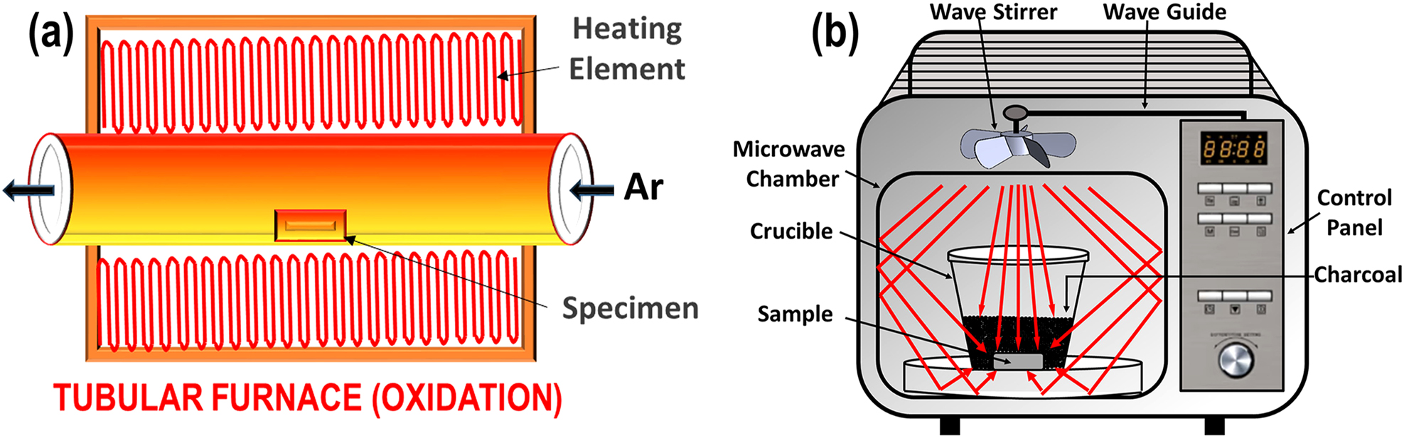
Schematic representation of (a) furnace annealing and (b) microwave processing.
2.1.2 Microwave processing
Microwave heat treatment of the as-sprayed (AS, henceforth) coating specimen was performed. The specimen was kept in an alumina crucible and activated charcoal was filled in the alumina crucible. An alumina separator plate was placed in between the coating specimen and charcoal to avoid contamination. After that the crucible was placed inside the microwave chamber to begin the processing as shown in Figure 1b. The parameters set for the processing were 220 V, 720 W power and 150 s processing time with microwave frequency of 2.45 GHz. The levels of parameters, i.e. power and processing time were optimized based on the trial experiments to obtain the recrystallized microstructure.
2.1.3 Stationary friction processing
Severe surface deformation of the AS coating specimen was achieved by using stationary friction processing (SFP). SFP is a modification of friction stir processing in which cylindrical tool is kept on rotating at the same location without traverse movement for certain time for localized microstructural refinement and specific property enhancement (Garg 2023). A WC pin-less tool of 12 mm diameter was rotated and inserted into the coating specimen. The tool was kept on rotating with a rotational speed of 388 rpm on the same location for 5 min. The plunge depth provided to the coating was 0.15 mm. These parameters were chosen based on trial studies to obtain microstructural homogenization. The schematic illustration of the SFP is shown in Figure 2.
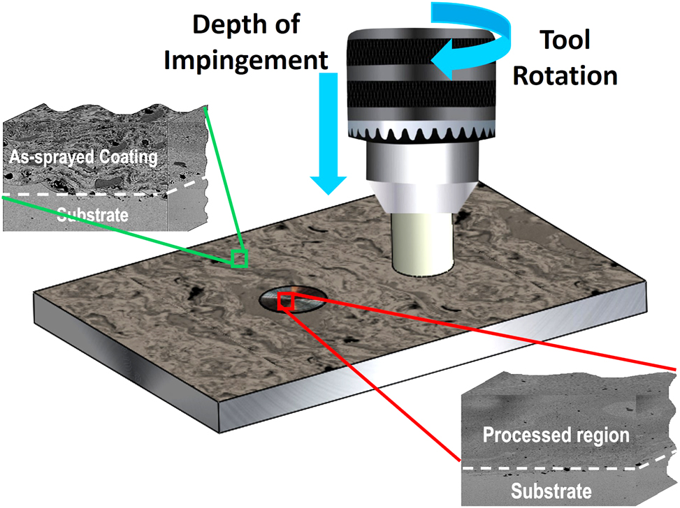
Schematic representation of stationary friction processing (SFP).
2.2 Microstructural characterization
All the processed and unprocessed coating specimens were cut along the diagonal, mounted the cross-section and polished till 2000 grit SiC emery paper followed by ultrasonic cleaning in ethanol. Cross section images of all the specimens were collected using field emission scanning electron microscopy (FESEM, JEOL JSM-7610 Plus) supplemented by energy dispersive X-ray spectroscopy (EDS, EDAX-AMETEK). X-ray diffraction (Bruker, D8 Discover) pattern of each specimen was obtained in a 2θ range of 20°–90° with a 0.01313° step size and 0.02°/s scan rate using a Cu-kα source of radiation (λ = 1.54 Å).
2.3 Mechanical characterization
Microhardness and fracture toughness measurements were performed using micro-indentation testing. Microhardness (Make: Wilson MV-420D) testings were performed along the cross-section of coating of processed and unprocessed specimens using Vickers indenter at 100 g load and 10 s dwell time. The strain rate during the time of indentation was 0.1 s−1. Along with cross-section, indentations on the surface were also taken at 5 different locations and crack lengths were measured during each indent in order to calculate fracture toughness. Evans and Wilshaw proposed a convenient way to estimate the fracture toughness (K C ) using micro-indentation (Nair et al. 2017).
where, H v shows the value of Vickers hardness (MPa), a represents half-length of indent diagonal (m), c is the crack length (m) from the center of the indent to the crack tip.
2.4 Slurry erosion and erosion corrosion
Slurry erosion of all the coating specimens was performed using a recirculatory type test rig. The test rig was chosen in compliance with ASTM G-73 standards. The test rig consists of a diaphragm pump powered by pneumatic system and a 2 mm diameter WC-nozzle. The outlet of diaphragm pump is connected to the nozzle from which high pressure slurry jet impinges on the specimen. In order to prevent the sedimentation of the river sand, slurry mixture was stirring concurrently with the slurry erosion testing. A vertical mechanical stirrer was used for the same. The slurry for the erosion testing was prepared using 0.5 wt% of river sand in distilled water while a 3.5 wt% NaCl salt was also mixed in this slurry for erosion-corrosion testing. Supplementary Figure S1 shows the back-scattered electron (BSE) image of the river sand. Supplementary Table S2 depicts the control parameters for the slurry test apparatus. The slurry tests were conducted at least thrice for each set of specimens to ensure repeatability.
2.5 Electrochemical corrosion
The corrosion resistance of the unprocessed and processed coating specimens was evaluated by potentiodynamic polarization measurements and electrochemical impedance spectroscopy (EIS). Electrochemical measurements were performed in a standard three electrode cell using Gamry potentiostat (Gamry Interface-1000E). A saturated calomel electrode (SCE), graphite electrode and coated specimen were used as reference, counter and working electrodes, respectively. A 3.5 % NaCl salt in distilled water, electrolytic solution (aerated) was prepared for immersing three electrodes. All the tests were performed at room temperature. Prior to potentiodynamic polarization, open circuit potential (OCP) of the specimen was collected till 1 h to achieve stable OCP. The potentiodynamic polarization was performed in a voltage range of −0.25 V to 0.4 V with a scan rate of 0.167 mV/s. In addition, impedance spectra were obtained in a frequency range of 0.01 Hz–100 kHz by applying a fixed amplitude of 10 mV AC voltage. The scan rate used to scan this frequency range is 10 points/decade. The obtained impedance spectra were modelled using an equivalent electrical circuit (EEC) and data was fitted using simplex algorithm in Gamry E-chem analyst 7.05 software. All the specimens were repeated atleast thrice for gauging the corrosion performance and ensure consistency.
3 Results and discussion
3.1 Microstructure
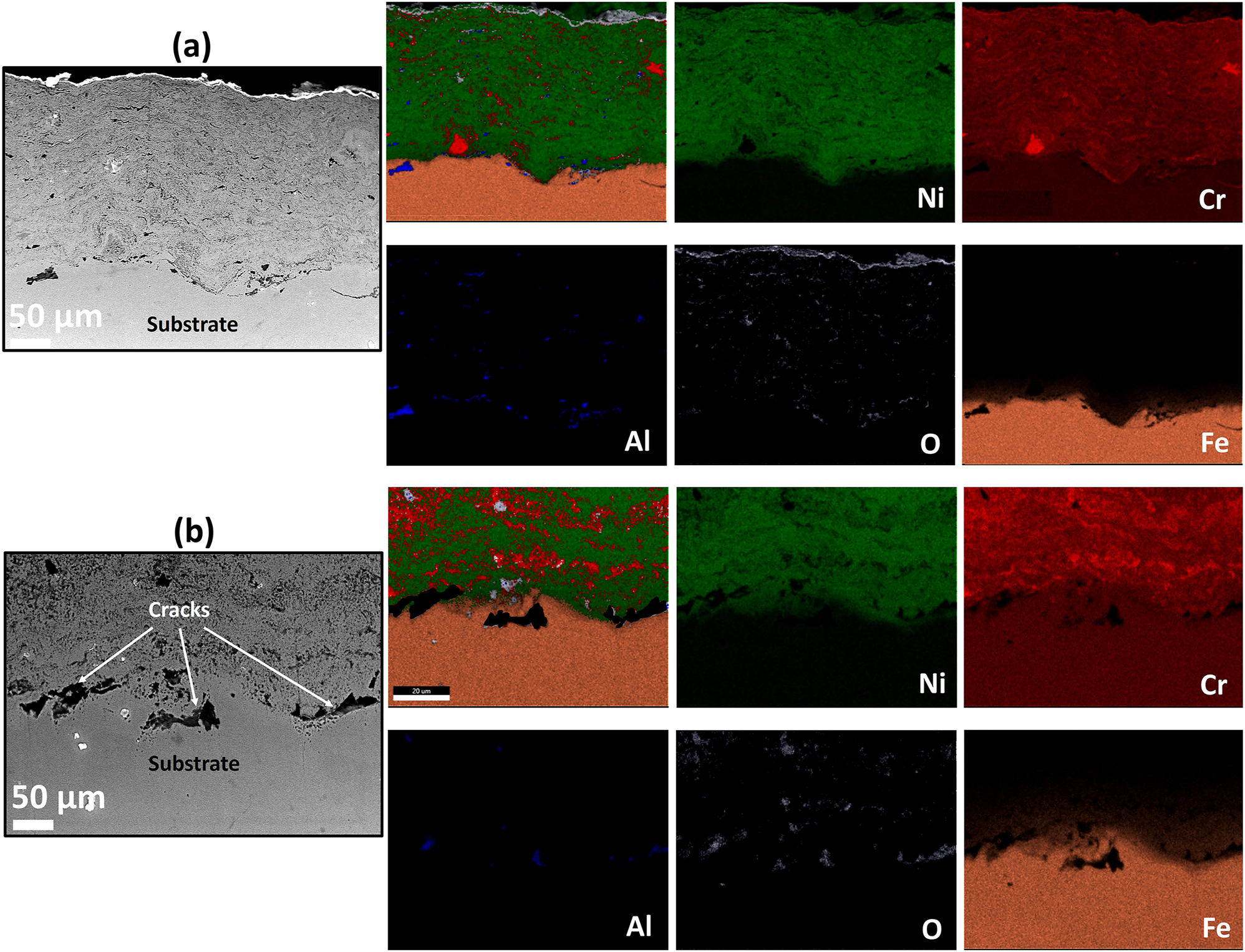
The cross-section BSE images along with EDS elemental maps of the AS and furnace annealed (FA) coating specimens are shown in Figures 3–5, respectively. Similarly, BSE images and elemental maps for the microwave processed (MWP) and SFP coating specimens are provided in Figures 6 and 7, respectively. The BSE image reveals a non-homogeneous microstructure and segregation of elements (Ni and Cr predominantly) of the AS-HVOF coating specimen. Also, AS coating exhibits Cr-rich splats. The average thickness of the coating specimens is nearly ∼280 µm. Post processing techniques homogenized the microstructure of the coating specimens. The specimen annealed at 900 °C for 5 min (FA11, henceforth) indicates homogeneous microstructure (Figure 4a) with an intact coating/substrate interface while specimen annealed at 900 °C for 15 min (FA12, henceforth) shows (Figure 4b) a little crack at the interface. Further, coating specimens annealed at 1,100 °C for 5 min (FA21, henceforth) and 15 min (FA22, henceforth) show (Figure 5) poor interfacial adhesion and cracking at the coating/substrate interface. The interfacial cracking is attributed to the mismatch of thermal expansion coefficient of coating and substrate at high temperature. In addition, high magnification cross-section images of the MWP specimen are shown in Figure 6. MWP specimen exhibits homogeneous microstructure while some sort of splat boundaries are visible in the cross-section BSE image. In contrast, SFP specimen (Figure 7) depicts a complete homogenization of the AS coating with no visible splats.
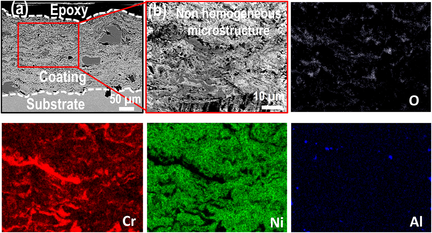
Cross-section morphology of the as-sprayed (AS) coating at (a) low magnification and (b) high magnification along with its corresponding EDS elemental mapping.
Cross-section EDS elemental mapping of the (a) FA11 and (b) FA12 coating.
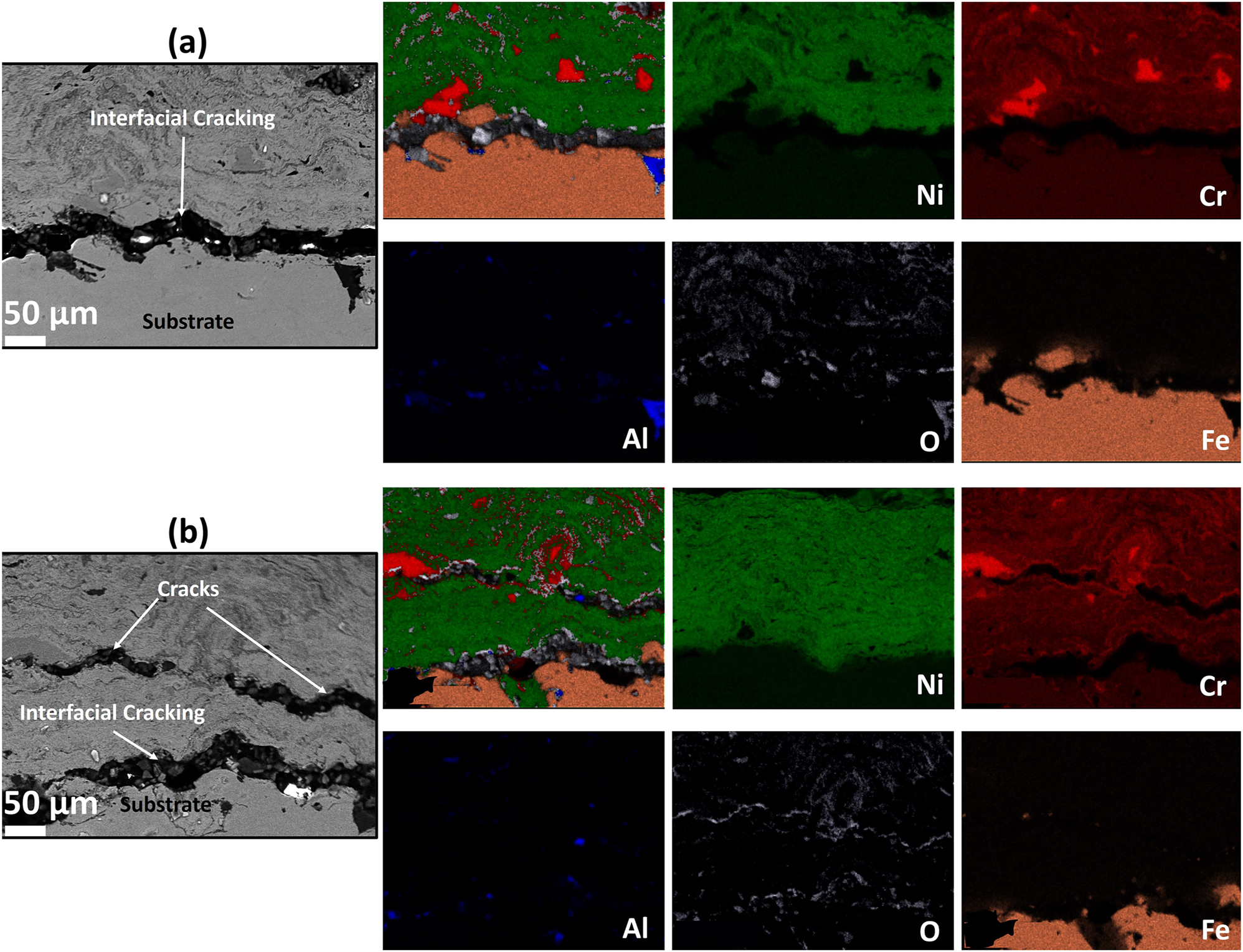
Cross-section EDS elemental mapping of the (a) FA21 and (b) FA22 coating.
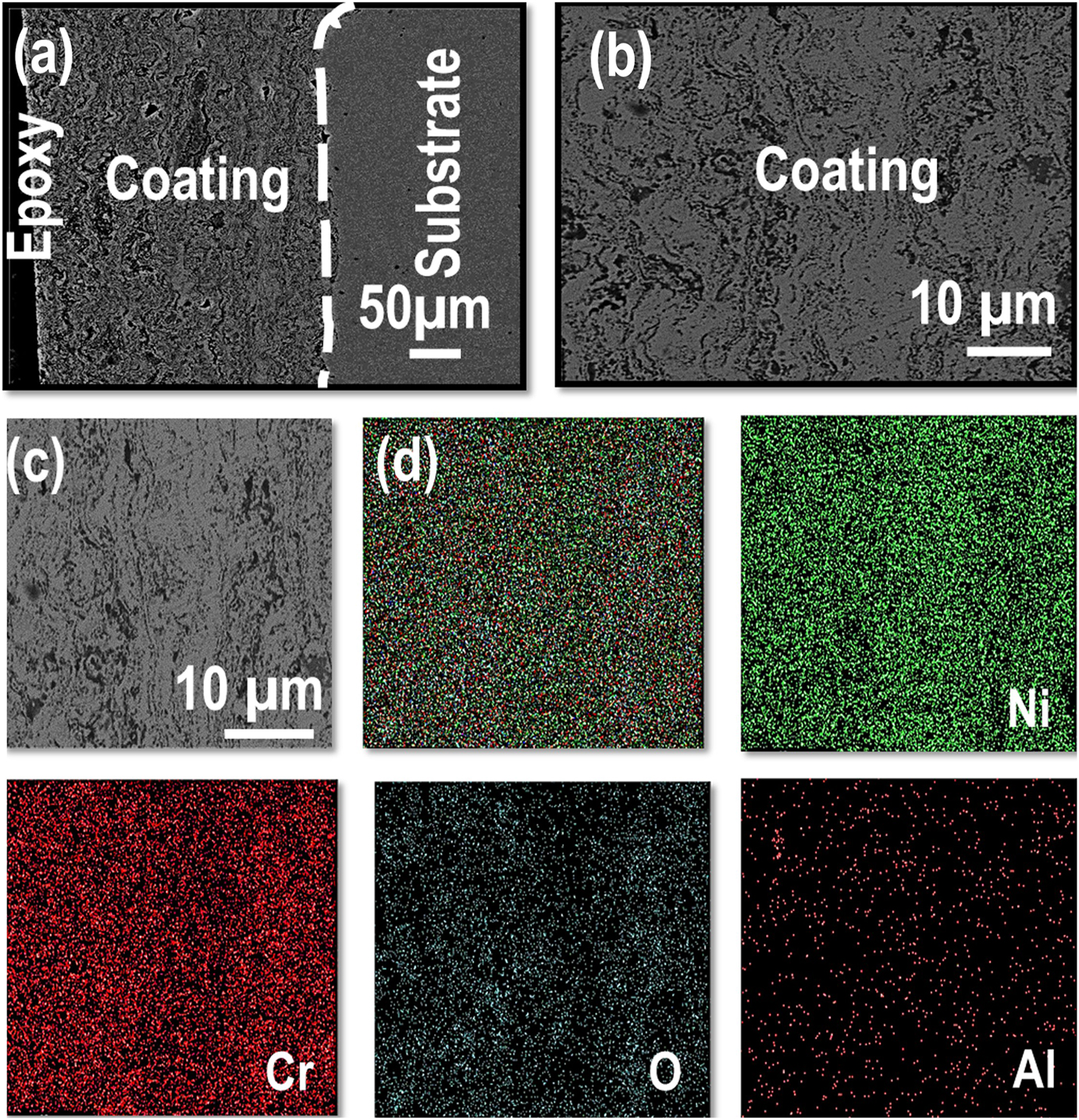
Microstructure analysis of MWP coating; (a, c) cross-section, (b) surface morphology, and (d) EDS elemental mapping corresponding to (c).
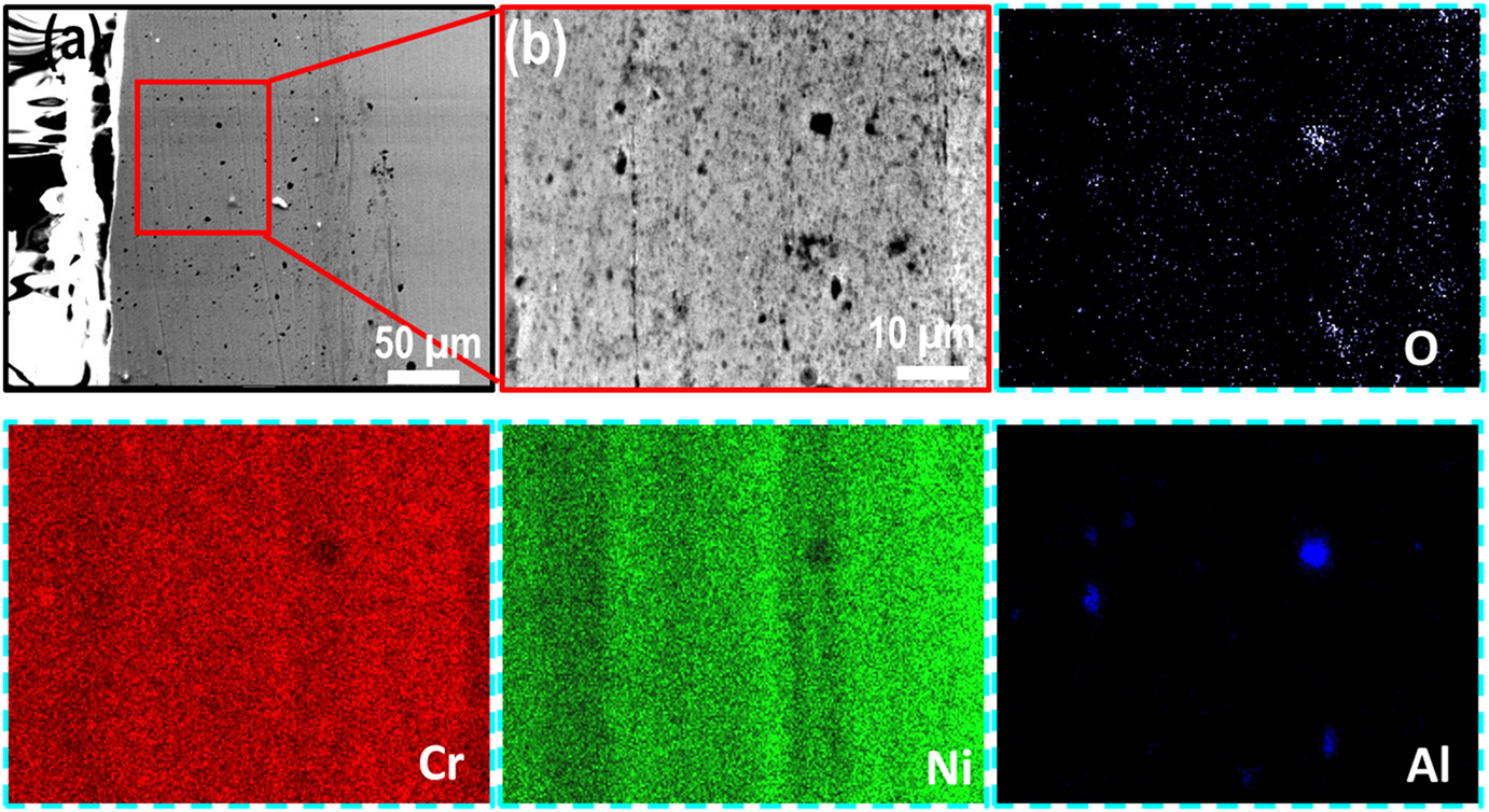
Cross-section morphology of the SFP coating at (a) low magnification and (b) high magnification along with its corresponding EDS elemental mapping.
The microstructure of the furnace annealed (FA11) and MWP specimens is homogenized, however, a small amount of splats was detected. The homogenization of the coating is likely to occur due to elemental diffusion at high temperature (Garg et al. 2021). Besides this, the elemental diffusion caused by combined action of thermal and strain field is attributed to the microstructural refinement during SFP (Figure 7). Thermal softening owing to the friction between the tool/workpiece interface and high strain rate during SFP resulted in the recrystallization of splats. Further, high temperature field and longer processing time facilitates the thermoplastic column (stir zone) to propagate down towards the interface and hence producing a more uniform and homogeneous coating throughout its thickness. In contrast, no strain field was provided during microwave processing or furnace annealing and only the thermal flux was attributed for the homogenization. It is apparent that the use of only thermal field is not sufficient to eliminate all of the splat boundaries. However, thermal heating during furnace annealing or microwave processing resulted in consistent elemental distribution. To characterize microstructure further, XRD measurements were performed on all the FA, AS, MWP and SFP specimens as shown in Figure 8a and b. AS specimen exhibits the availability Ni, Cr, Al along with the formation of several elemental compounds C6Cr23, Al2O3 and NiCr2O4. Besides this, a few low intensity peaks of CrO3 and Cr2O3 were also observed in the same specimen. CrO3, Cr2O3 and NiCr2O4 are likely to form during the time of coating deposition at high temperature. MWP specimen also depicts almost the same signature of XRD spectrum. However, peaks of Cr, Al and C6Cr23 were disappeared likely due to the enhanced elemental diffusion kinetics during microwave processing. Interestingly, SFP specimen shows the dissolution of most of the elemental compounds into the intragranular region of the coating owing to the high strain and temperature field. In addition, SFP favors the formation of NiCr solid solution evident from XRD spectrum. Furthermore, XRD analysis of all the furnace annealed specimens is displayed in Figure 8b. Furnace annealing of the coating specimen also favors the formation of NiCr solid solution and the peak intensity increased with increase in annealing temperature and the annealing time for the same. In addition, FA also resulted in dissolution of Cr, Al and C6Cr23 owing to the elemental diffusion at high temperature field.
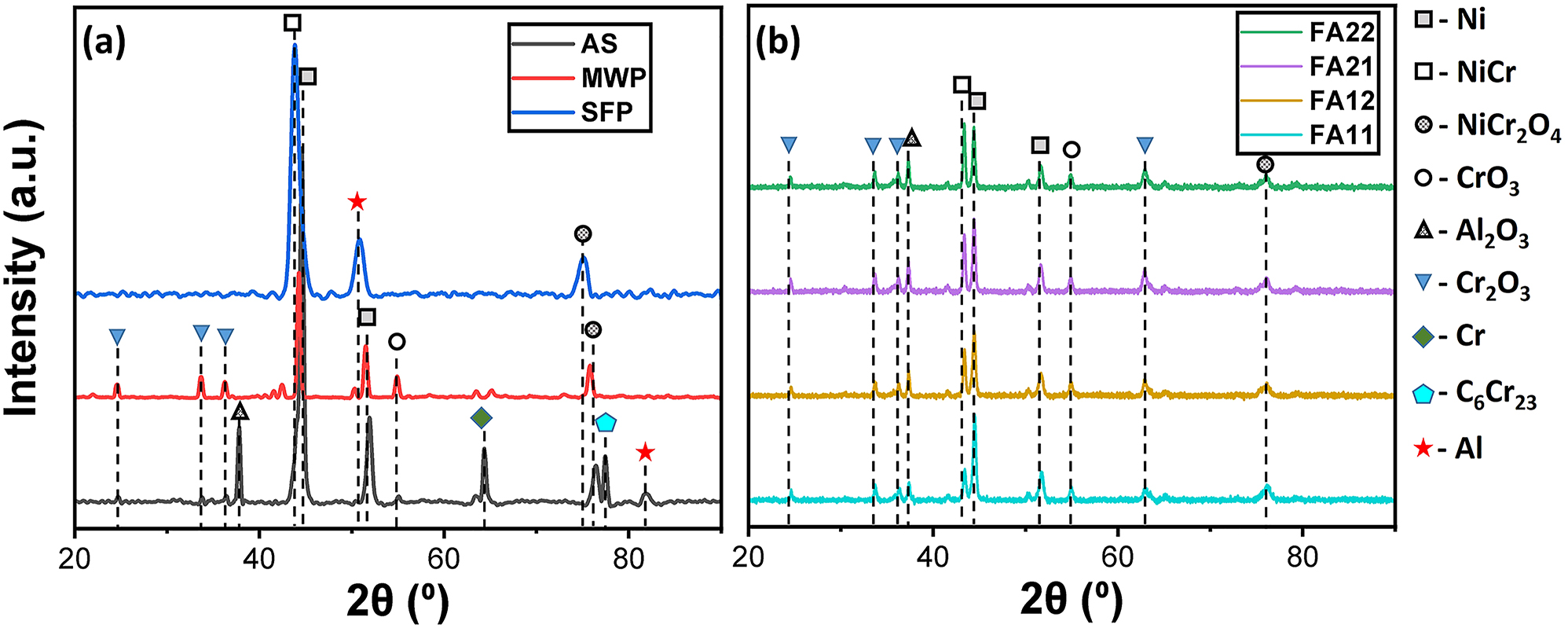
XRD spectra of (a) AS, MWP, SFP and (b) FA coating specimens.
3.2 Mechanical properties
The variation of fracture toughness values for specimens processed through different processing routes are shown in Figure 9. The average fracture toughness for AS, FA11, FA12, FA21 and FA22 specimens was obtained as 5.34 MPa √m, 8.13 MPa √m, 7.6 MPa √m, 6.59 MPa √m and 5.17 MPa √m. The error bar shows the standard deviation of the fracture toughness from its mean (average) position. Thus, it can be seen that coating specimens annealed at 1,100 °C shows a marginal increase (5 %–23 %) in fracture toughness while specimens annealed at 900 °C shows a significant increase (43 %–53 %) in the fracture toughness values as compared to AS coating. In addition, MWP and SFP specimens exhibit fracture toughness values nearly ∼7.5 MPa √m and ∼8.41 MPa √m, respectively. Further, the variation of micro-hardness along the depth of coating thickness for all the annealed specimens is shown in Figure 10a. Also, the best specimen among annealing was compared with the as-sprayed, MWP and SFP specimens (Figure 10b). The micro-hardness profile shows a gradual decrease in hardness with the increase in distance from top surface. The peak hardness values for as-sprayed, FA11, FA12, FA21, FA22, MWP and SFP specimens are obtained as 500 H V, 675 H V, 605 H V, 560 H V, 537 H V, 615 H V and 850 H V, respectively. Thus, furnace annealing at 900 °C, clearly demonstrates better mechanical properties as compared to furnace annealing at 1,100 °C. In addition, only 5 min of furnace annealing at 900 °C shows the optimum annealing parameters for obtaining better mechanical properties. Degradation in mechanical properties at high temperature annealing is attributed to the poor adhesion of the coatings at the interface. This is due to the mismatch of coefficient of thermal expansion between the coating and substrate at high temperature. Even, FA11 is better than MWP specimen in terms of mechanical properties while SFP specimen exhibits superior mechanical properties than all the other coating specimens. Since, the coating defects like splats, porosity and splat boundaries are prone to initiation and propagation of cracks. SFP completely removes these coating defects, homogenizes it throughout the thickness and hence responsible for the superior mechanical properties for the same. Also, the partial removal of splat boundaries and other defects during MWP and FA goes well with their inferior mechanical properties compared to SFP specimen.
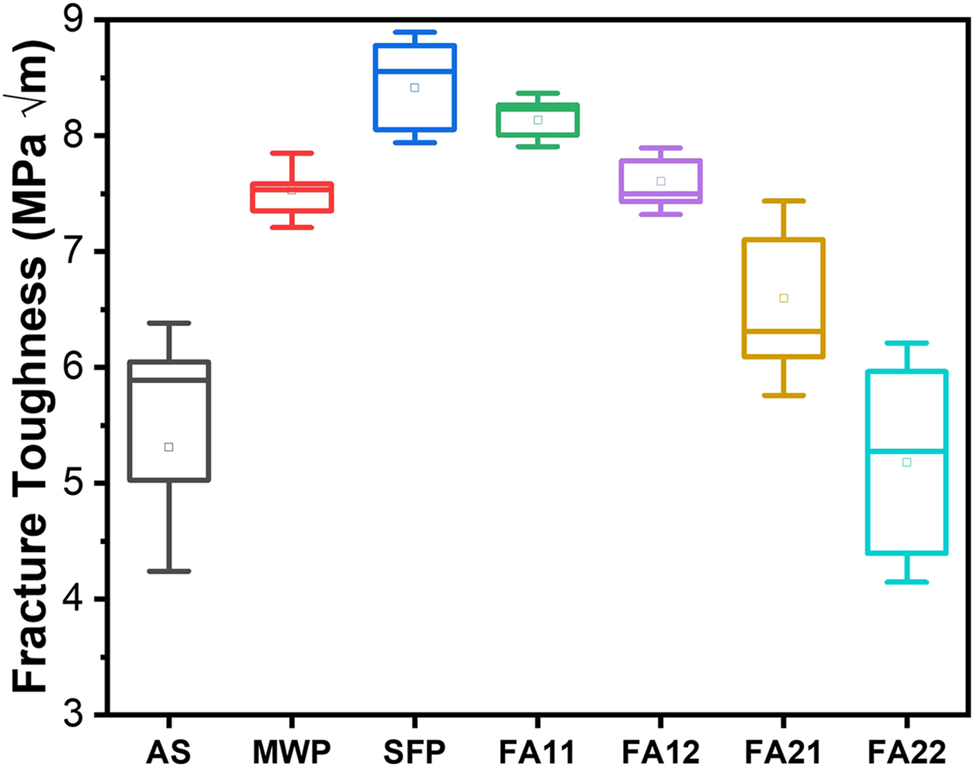
Variation of fracture toughness values with different post processing techniques.
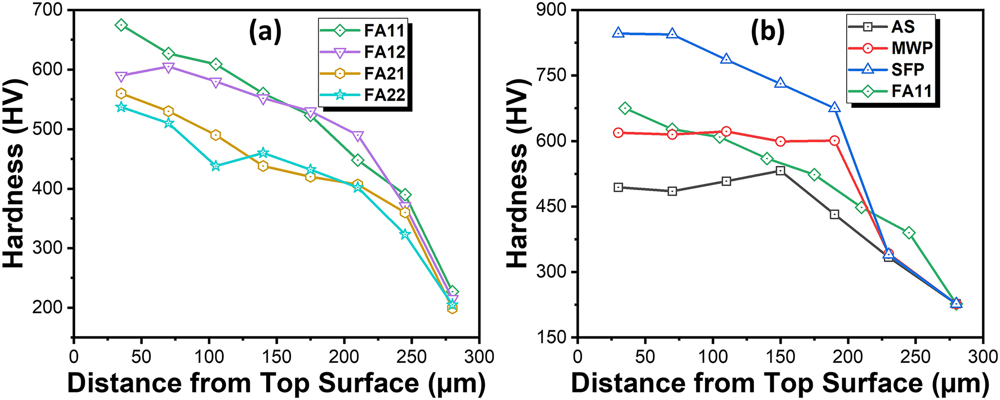
Variation of micro-hardness across the coating depth for (a) furnace annealed coating specimens and (b) specimens with different processing routes.
3.3 Slurry erosion studies
The erosion rate for slurry erosion was plotted in the bar graph as shown in Figure 11a. The erosion rate of AS, FA11, FA12, FA21, FA22, MWP and SFP specimens are 0.33 mm3/h, 0.14 mm3/h, 0.17 mm3/h, 0.18 mm3/h, 0.25 mm3/h, 0.27 mm3/h and 0.1 mm3/h at 30° of the impingement angle. Similarly, erosion rate of the same specimens at 90° of the impingement angle are 0.20 mm3/h, 0.16 mm3/h, 0.19 mm3/h, 0.24 mm3/h, 0.28 mm3/h, 0.15 mm3/h and 0.13 mm3/h, respectively. The error bars indicate the standard deviation of erosion rate from their mean position. Clearly, furnace annealing of coating specimens at 900 °C shows the higher erosion resistance as compared to furnace annealing at 1,100 °C and FA11 specimen shows the superior erosion resistance among all the furnace annealed specimens. High erosion resistance of the FA11 specimen is attributed to its high value of micro-hardness and fracture toughness. In addition, there is no cracking observed at the coating/substrate interface for FA11 specimen which indicates its better adhesion properties. In contrast, poor interfacial adhesion between coating and substrate is responsible for the low erosion resistance of the coatings annealed at 1,100 °C. Further, FA12 specimen also shows some cracking at the coating/substrate interface which deteriorates its mechanical properties. Among FA, MWP and SFP, SFP specimen is exhibiting the highest erosion resistance. This is attributed to the complete removal of the coating defects during SFP owing to the concurrent thermal and strain field effects which ultimately results in the enhancement of hardness and fracture toughness. The results of erosion corrosion are shown in Figure 11b. As compared to pure slurry erosion all the coating specimens demonstrated a slight increment in the erosion rate under erosion corrosion condition at 30° impingement angle while a significant increment in the erosion rate is observed at 90° impingement angle. Similar to slurry erosion, erosion corrosion behavior of FA11 specimen shows superior erosion resistance among furnace annealed specimens while SFP specimen shows best performance out of all the specimens.
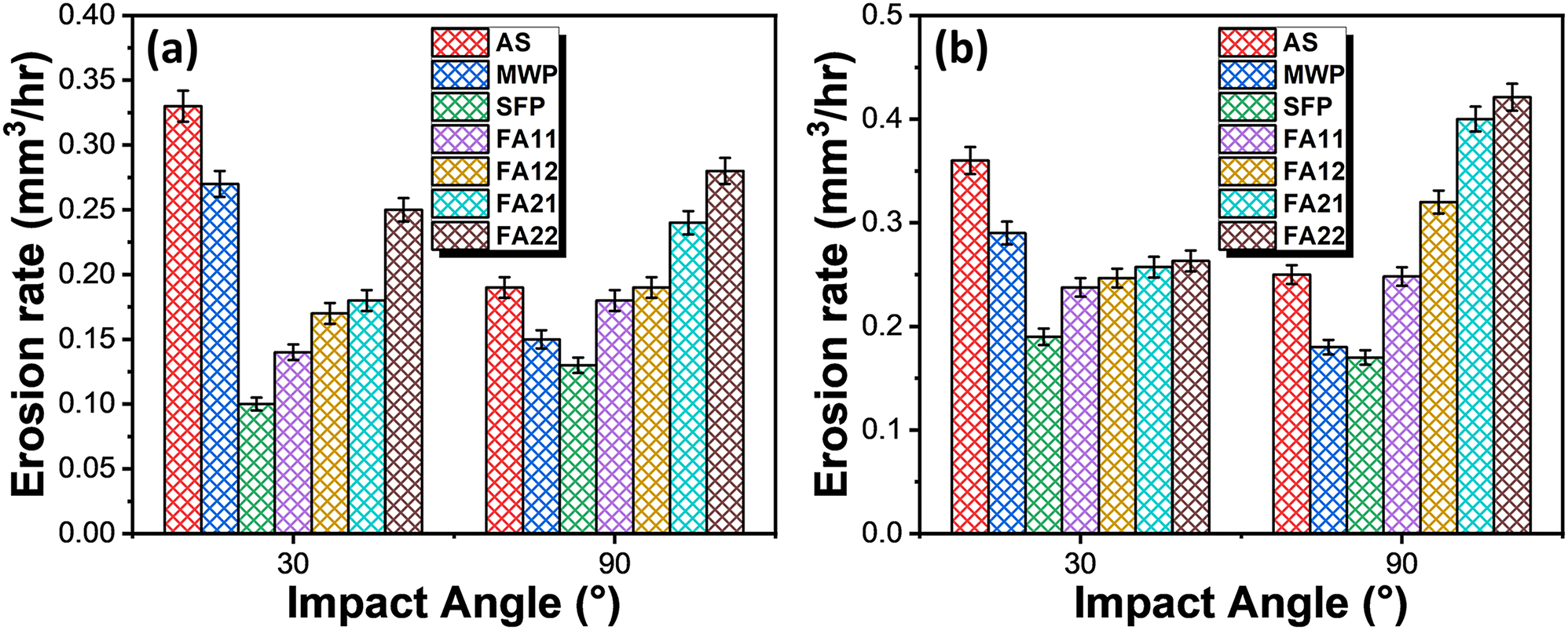
Cumulative volume loss per hour as a function of impact angle for coating specimens processed through different processing routes under (a) slurry erosion and (b) erosion-corrosion test conditions.
BSE images illustrating the surface morphology of the eroded AS and SFP specimen after slurry erosion testings are shown in Figure 12. Detailed examination of the eroded surfaces for the AS and SFP specimen (placed at oblique angle) depicts the mechanism of extensive plastic deformation in the form of platelets built up by the impact of slurry erosives. The mechanism comprises of formation of craters by the erosive attack, dragging out the material nearby the craters and eventually shoring of the material at the crater tip. Subsequently, these platelets are compressed and twisted along the projection of craters (Figure 12a and b). In addition to platelet growth, evidence of plowing, micro-cutting, micropores and micro-indents by the impact of erosive particles are clearly observable and mentioned on the BSE-SEM images. However, the mechanism of plastic deformation seems to be much lesser for SFP coating (Figure 12e and f) than AS coating (Figure 12a and b). The result goes well with the enhanced fracture toughness and hardness of the SFP specimen which are considered as the key factors regulating the material’s deterioration. During orthogonal impingement, material degradation is observed predominantly in the form of cracking of splats for AS coating as shown in Figure 12c and d. This is attributed to the lack of plastic deformation of the AS specimen during the normal impingement of the erosive. On the contrary, SFP specimen depicts the mechanism of platelet growth instead of splats cracking (the case for AS coating). Even, this can be described in terms of high hardness value of the SFP specimen than AS specimen.
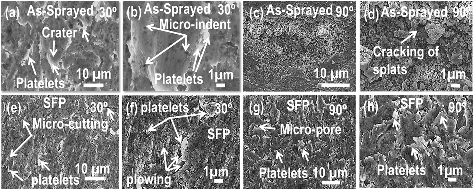
High magnification BSE images showing eroded surfaces after slurry erosion test at (a–b) 30° impingement and (c–d) 90° impingement for the AS coating, (e–f) 30° impingement and (g–h) 90° impingement for SFP coating.
3.4 Corrosion behavior
The corrosion behavior of all the coating specimens is studied by potentiodynamic polarization and electrochemical impedance spectroscopy (EIS). Figure 13a and b shows the results of potentiodynamic polarization for AS, FA, MWP and SFP specimens. The corrosion current and corrosion rate are calculated from polarization curve using Tafel fit and the fitting parameters are given in Table 1. Among furnace annealed specimens, the corrosion rate of the FA11 was lowest followed by FA12, FA21 and FA22. High corrosion resistance of the FA11 specimen is attributed to the microstructural homogenization while poor corrosion behavior of the other annealed specimens is attributed to the presence of pores, cracks and interfacial cracking which favor the penetration of the electrolyte into the coating. In addition, comparison of corrosion performance of FA11 specimen with the AS, MWP and SFP specimen is shown in Figure 13b. AS specimen depicts high corrosion current density (I corr) followed by FA11, MWP and SFP. High corrosion current in the AS coating is attributed to the presence of high fraction of defects like pores and splat boundaries etc. These pores and splat boundaries are prone to aggravate corrosion phenomenon and favors the electrolyte to penetrate at these sites. Partial removal of these defects by FA and MWP resulted in decreased value of corrosion current density. In contrast, complete homogenization of TSC via SFP is responsible for the least I corr value.
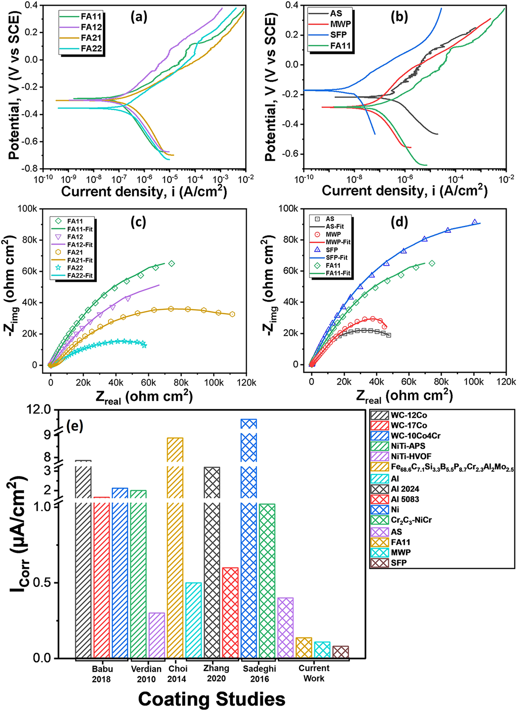
Potentiodynamic polarization curves for (a) FA coating specimens, (b) specimens with different processing routes; EIS curves showing the Nyquist plot for (c) FA coating specimens, (d) specimens with different processing routes; (e) comparison of corrosion performance of NiCr-5Al2O3 coatings with other coatings in 3.5 % NaCl solution.
Comparison of corrosion performance of Ni-Cr-5Al2O3 coatings with literature in 3.5 % NaCl solution at room temperature.
| Coating specimens | I corr (A/cm2) | E corr (mV versus SCE) | CR (mpy) | References |
|---|---|---|---|---|
| AS | 4 × 10⁻⁷ | −217 | 0.131 | Current work |
| MWP | 1.08 × 10⁻⁷ | −286 | 0.052 | |
| SFP | 8 × 10⁻⁸ | −162 | 0.026 | |
| FA11 | 1.37 × 10⁻⁷ | −284 | 0.072 | |
| FA12 | 1.84 × 10⁻⁷ | −296 | 0.096 | |
| FA21 | 2.34 × 10⁻⁷ | −298 | 0.122 | |
| FA22 | 3.05 × 10⁻⁷ | −354 | 0.160 | |
| Al3Ni2 | 6 × 10⁻³ | −735 | – | Zhang and Kong (2018) |
| Al3Ni1 | 6.3 × 10⁻³ | −913 | – | |
| Al4Ni1 | 2.8 × 10⁻³ | −727 | – | |
| NiTi-APS | 2 × 10⁻⁶ | −320 | – | Verdian et al. (2010) |
| NiTi-HVOF | 3 × 10⁻⁷ | −470 | – | |
| WC-12Co | 7.8 × 10⁻⁶ | −586 | – | Babu et al. (2018) |
| WC-17Co | 1.6 × 10⁻⁶ | −621 | – | |
| WC-10Co4Cr | 2.1 × 10⁻⁶ | −420 | – | |
| Al | 5 × 10⁻⁷ | −880 | – | Zhang et al. (2020) |
| Al 2024 | 3.2 × 10⁻⁶ | −710 | – | |
| Al 5083 | 6 × 10⁻⁷ | −870 | – | |
| Ni | 1.2 × 10⁻⁵ | −440 | – | Sadeghi et al. (2016) |
| Cr2C3–NiCr | 1.02 × 10⁻⁶ | −240 | – | |
| Fe68.6C7.1Si3.3B5.5P8.7Cr2.3Al2.0Mo2.5 | 8.8 × 10⁻⁶ | −250 | – | Choi et al. (2014) |
| Fe48Cr15Mo14C15B6Y2 | 2.1 × 10⁻⁵ | −410 | – | Zhou et al. (2009) |
| Zn–15Al | 13.2 × 10⁻⁶ | −962 | – | Yung et al. (2019) |
| IN625 | 15.5 × 10⁻⁶ | −405 | – |
The corrosion performance of the NiCr-5Al2O3 (AS, FA11, MWP and SFP) coating specimens is also compared with other erosion-corrosion resistant coating (Babu et al. 2018; Choi et al. 2014; Sadeghi et al. 2016; Verdian et al. 2010; Yung et al. 2019; Zhang and Kong 2018; Zhang et al. 2020; Zhou et al. 2009) systems as well, and the comparison is shown in Table 1 and Figure 13e. All these coatings were tested in 3.5 % NaCl solution at room temperature. The corrosion current density of AS NiCr-5Al2O3 coating is lower compared to other coating systems except NiTi-HVOF coating. However, SFP coating specimen exhibits the least corrosion current density indicating its superior corrosion resistance. The exceptional corrosion resistance of the SFP processed NiCr-5Al2O3 coating obtained in this study is of significant importance for high efficiency engineering systems.
Furthermore, impedance spectra of the TSC specimens is obtained in the Nyquist plots as shown in Figure 13c and d. The semicircular loop radius of the impedance spectra depicts the polarization resistance of the coating specimens. The FA11 specimen exhibits highest polarization resistance followed by FA12, FA21 and FA22 as shown in Figure 13c. Besides this, impedance behavior of FA11 specimen was compared with the AS, MWP and SFP specimen (Figure 13d) which indicates superior polarization resistance of SFP specimen among all. The results of EIS measurements are in line with the potentiodynamic polarization measurements. High polarization resistance is attributed to the removal of splat boundaries and pores, which provides the diffusion channels for the electrolyte to penetrate, limiting the penetration of electrolyte through coating. However, poor impedance behavior of coating specimens annealed at 1,100 °C is attributed to the presence of cracks and poor interfacial adhesion between the coating and substrate. Therefore, specimens annealed at 1,100 °C fails to restrict the penetration of electrolyte through the coating. The modelling of impedance spectra was performed by applying a simplex algorithm using electrical equivalent circuit (EEC) to obtain electrical characteristics of the coating specimens. A two-time constant EEC was utilized for the fitting of impedance spectra of AS, FA, MWP and SFP coating specimens as shown in Supplementary Figure S2. Here, R s is the solution resistance, CPEdl and R ct are the constant-phase element of double layer and charge transfer resistance, respectively. R p is the polarization resistance of the coating and CPE c represents the constant phase element for the coating. Table 2 summarizes the values of fitting parameters (electrical properties) indicating high polarization resistance for the SFP specimen in line with the results of impedance spectra.
EIS fitting parameters for Ni-Cr-5Al2O3 coatings.
| Specimen | Rp (kohm cm2) | CPEc (µS sn cm−2) | n 1 | Rct (kohm cm2) | CPEdl (µS sn cm−2) | n 2 |
|---|---|---|---|---|---|---|
| AS | 72.33 | 43.78 | 0.918 | 1.18 | 120.4 | 0.754 |
| MWP | 75.12 | 30.79 | 0.59 | 2.22 | 10.71 | 0.62 |
| SFP | 240.0 | 13.73 | 0.650 | 68.98 | 98.60 | 0.901 |
| FA11 | 235.3 | 35.62 | 0.855 | 4.653 | 101.0 | 0.763 |
| FA12 | 206.27 | 72.24 | 0.601 | 0.179 | 27.92 | 0.616 |
| FA21 | 128.22 | 15.13 | 0.78 | 3.83 | 4.40 | 0.64 |
| FA22 | 63.79 | 64.37 | 0.77 | 0.165 | 280.3 | 0.91 |
4 Conclusions
In the current study, the effect of FA, MWP and SFP to the NiCr-5Al2O3 TSCs microstructure, mechanical properties, slurry erosion and corrosion behavior was investigated. FA and MWP partially homogenize the microstructure of TSC while SFP is able to completely refine and rejuvenate the microstructure of TSC. Structural rejuvenation is attributed to the dissolution of pores, splats and segregated elements at high temperature and high strain rate during SFP. FA, MWP and SFP coating specimens show nearly ∼1.35, 1.23 and 1.7 times high micro-hardness as compared to AS coating. Similarly, SFP coating specimen indicates superior performance under slurry erosion conditions followed by FA11 and MWP which is in line with the results of mechanical properties as well. Additionally, standalone corrosion studies demonstrate the highest corrosion resistance of the SFP assisted coating specimen followed by MWP, FA11 and AS coating, responsible for the exceptional erosion corrosion resistance of the SFP assisted coating. Thus, the results of present study suggest that stationary friction processing is a highly effective and adaptable approach for significantly improving the degradation resistance of TSCs through microstructural rejuvenation.
Funding source: Naval Research Board (NRB)
Award Identifier / Grant number: project number: NRB-399/MAT/17-18
Acknowledgements
This work was presented at the 7th World Tribology Congress (WTC)-2022 held in Lyon, France.
-
Research ethics: Not applicable.
-
Author contributions: Mayank Garg: data curation, investigation, formal analysis, writing – original draft. Harpreet S. Grewal: supervision, writing – review & editing. Harpreet Singh Arora: conceptualization, methodology, supervision, writing – review & editing. The authors have accepted responsibility for the entire content of this manuscript and approved its submission.
-
Use of Large Language Models, AI and Machine Learning Tools: None declared.
-
Conflict of interest: The authors state no conflict of interest.
-
Research funding: This research was supported by the project titled “Modulating Coating Properties for Enhanced Protection from Erosion-Corrosion: a Systematic Approach on Delineating the Effect of Post-Processing Conditions”, Naval Research Board (NRB), project number: NRB-399/MAT/17–18.
-
Data availability: Not applicable.
References
Arora, H.S., Rani, M., Perumal, G., and Grewal, H.S. (2020a). Enhanced cavitation erosion–corrosion resistance of high-velocity oxy-fuel-sprayed Ni-Cr-Al2O3 coatings through stationary friction processing. J. Therm. Spray Technol. 29: 1183–1194, https://doi.org/10.1007/s11666-020-01050-5.Suche in Google Scholar
Arora, H.S., Rani, M., Perumal, G., and Grewal, H.S. (2020b). Facile and green engineering approach for enhanced corrosion resistance of Ni-Cr-Al2O3 thermal spray coatings. ACS Omega 5: 24558–24566, https://doi.org/10.1021/acsomega.0c03053.Suche in Google Scholar PubMed PubMed Central
Arora, H.S., Rani, M., Perumal, G., Grewal, H.S., and Singh, H. (2020c). Structural rejuvenation of thermal spray coating through stationary friction processing. Surf. Coat. Technol. 389: 125631, https://doi.org/10.1016/j.surfcoat.2020.125631.Suche in Google Scholar
Babu, P.S., Madhavi, Y., Rama Krishna, L., Srinivasa Rao, D., and Padmanabham, G. (2018). Thermally-sprayed WC-based cermet coatings for corrosion resistance applications. JOM 70: 2636–2649, https://doi.org/10.1007/s11837-018-3131-6.Suche in Google Scholar
Bergant, Z., Trdan, U., and Grum, J. (2014). Effect of high-temperature furnace treatment on the microstructure and corrosion behavior of NiCrBSi flame-sprayed coatings. Corros. Sci. 88: 372–386, https://doi.org/10.1016/j.corsci.2014.07.057.Suche in Google Scholar
Chen, Y., Fan, B., Yang, B., Ma, W., Liu, G., and Li, H. (2019). Microwave sintering and fracture behavior of zirconia ceramics. Ceram. Int. 45: 17675–17680, https://doi.org/10.1016/j.ceramint.2019.05.334.Suche in Google Scholar
Cho, J.E., Hwang, S.Y., and Kim, K.Y. (2006). Corrosion behavior of thermal sprayed WC cermet coatings having various metallic binders in strong acidic environment. Surf. Coat. Technol. 200: 2653–2662, https://doi.org/10.1016/j.surfcoat.2004.10.142.Suche in Google Scholar
Choi, S.J., Lee, H.S., Jang, J.W., and Yi, S. (2014). Corrosion behavior in a 3.5 wt% NaCl solution of amorphous coatings prepared through plasma-spray and cold-spray coating processes. Metals Mater. Int. 20: 1053–1057, https://doi.org/10.1007/s12540-014-6008-4.Suche in Google Scholar
Dong, Y., Yang, Y., Chu, Z., Zhang, J., He, J., Yan, D., and Li, D. (2017). Effect of annealing in Ar on the microstructure and properties of thick nano-grained TiN ceramic coatings. Ceram. Int. 43: 9303–9309, https://doi.org/10.1016/j.ceramint.2017.04.091.Suche in Google Scholar
Garg, M. (2023). Development of complex concentrated alloys for high temperature applications, Ph.D. thesis, Greater Noida, Shiv Nadar Institution of Eminence Deemed to be University.Suche in Google Scholar
Garg, M., Grewal, H.S., and Arora, H.S. (2021). Effect of microwave processing on the oxidation behavior of refractory high entropy alloy. Mater. Chem. Phys. 262: 124256, https://doi.org/10.1016/j.matchemphys.2021.124256.Suche in Google Scholar
Guilemany, J.M., Espallargas, N., Suegama, P.H., and Benedetti, A.V. (2006). Comparative study of Cr3C2-NiCr coatings obtained by HVOF and hard chromium coatings. Corros. Sci. 48: 2998–3013, https://doi.org/10.1016/j.corsci.2005.10.016.Suche in Google Scholar
Iizuka, N., Fukushima, J., Hayashi, Y., and Takizawa, H. (2022). Microwave-assisted titanium nitride coating processing using nitride powders in ambient atmosphere. J. Alloys Compd. 908: 164606, https://doi.org/10.1016/j.jallcom.2022.164606.Suche in Google Scholar
Kumar Goyal, D., Singh, H., Kumar, H., and Sahni, V. (2012). Slurry erosion behaviour of HVOF sprayed WC-10Co-4Cr and Al2O3+13TiO2 coatings on a turbine steel. Wear 289: 46–57, https://doi.org/10.1016/j.wear.2012.04.016.Suche in Google Scholar
Liu, Y., Hang, Z., Chen, H., Ceng, S., Gou, G., Wang, X., Tu, M., and Wu, X. (2016). Erosion–corrosion property of CeO2-modified HVOF WC-Co coating. J. Therm. Spray Technol. 25: 815–822, https://doi.org/10.1007/s11666-016-0391-y.Suche in Google Scholar
Matthews, S.J., James, B.J., and Hyland, M.M. (2007). Microstructural influence on erosion behaviour of thermal spray coatings. Mater. Charact. 58: 59–64, https://doi.org/10.1016/j.matchar.2006.03.014.Suche in Google Scholar
Mehta, J., Mittal, V.K., and Gupta, P. (2017). Role of thermal spray coatings on wear, erosion and corrosion behavior: a review. J. Appl. Sci. Eng. 20: 445–452.Suche in Google Scholar
Nair, R.B., Selvam, K., Arora, H.S., Mukherjee, S., Singh, H., and Grewal, H.S. (2017). Slurry erosion behavior of high entropy alloys. Wear 386–387: 230–238, https://doi.org/10.1016/j.wear.2017.01.020.Suche in Google Scholar
Nair, R.B., Arora, H.S., Boyana, A.V., Saiteja, P., and Grewal, H.S. (2019). Tribological behavior of microwave synthesized high entropy alloy claddings. Wear 436–437: 203028, https://doi.org/10.1016/j.wear.2019.203028.Suche in Google Scholar
Nicholls, J.R., Deakin, M.J., and Rickerby, D.S. (1999). A comparison between the erosion behaviour of thermal spray and electron beam physical vapour deposition thermal barrier coatings. Wear 233–235: 352–361, https://doi.org/10.1016/s0043-1648(99)00214-8.Suche in Google Scholar
Qin, Y., Zhao, H., Li, C., Lu, J., and He, J. (2020). Effect of heat treatment on the microstructure and corrosion behaviors of reactive plasma sprayed TiCN coatings. Surf. Coat. Technol. 398: 126086, https://doi.org/10.1016/j.surfcoat.2020.126086.Suche in Google Scholar
Sadeghi, E., Markocsan, N., Nylén, P., and Björklund, S. (2016). Corrosion performance of bi-layer Ni/Cr2C3–NiCr HVAF thermal spray coating. Appl. Surf. Sci. 369: 470–481, https://doi.org/10.1016/j.apsusc.2016.02.002.Suche in Google Scholar
Santa, J.F., Espitia, L.A., Blanco, J.A., Romo, S.A., and Toro, A. (2009). Slurry and cavitation erosion resistance of thermal spray coatings. Wear 267: 160–167, https://doi.org/10.1016/j.wear.2009.01.018.Suche in Google Scholar
Škamat, J., Černašėjus, O., Čepukė, Ž., and Višniakov, N. (2019). Pulsed laser processed NiCrFeCSiB/WC coating versus coatings obtained upon applying the conventional re-melting techniques: evaluation of the microstructure, hardness and wear properties. Surf. Coat. Technol. 374: 1091–1099, https://doi.org/10.1016/j.surfcoat.2019.06.080.Suche in Google Scholar
Škamat, J., Černašėjus, O., Zhetessova, G., Nikonova, T., Zharkevich, O., and Višniakov, N. (2021). Effect of laser processing parameters on microstructure, hardness and tribology of NiCrCoFeCBSi/WC coatings. Materials [Online] 14, https://doi.org/10.3390/ma14206034.Suche in Google Scholar PubMed PubMed Central
Toma, D., Brandl, W., and Marginean, G. (2001). Wear and corrosion behaviour of thermally sprayed cermet coatings. Surf. Coat. Technol. 138: 149–158, https://doi.org/10.1016/s0257-8972(00)01141-5.Suche in Google Scholar
Verdian, M.M., Raeissi, K., and Salehi, M. (2010). Corrosion performance of HVOF and APS thermally sprayed NiTi intermetallic coatings in 3.5 % NaCl solution. Corros. Sci. 52: 1052–1059, https://doi.org/10.1016/j.corsci.2009.11.034.Suche in Google Scholar
Wang, B. and Lee, S.W. (2000). Erosion–corrosion behaviour of HVOF NiAl–Al2O3 intermetallic-ceramic coating. Wear 239: 83–90, https://doi.org/10.1016/s0043-1648(00)00309-4.Suche in Google Scholar
Yung, T.-Y., Chen, T.-C., Tsai, K.-C., Lu, W.-F., Huang, J.-Y., and Liu, T.-Y. (2019). Thermal spray coatings of Al, ZnAl and Inconel 625 alloys on SS304L for anti-saline corrosion. Coatings [Online] 9, https://doi.org/10.3390/coatings9010032.Suche in Google Scholar
Zhang, D. and Kong, D. (2018). Microstructures and immersion corrosion behavior of laser thermal sprayed amorphous Al-Ni coatings in 3.5 % NaCl solution. J. Alloys Compd. 735: 1–12, https://doi.org/10.1016/j.jallcom.2017.11.054.Suche in Google Scholar
Zhang, Z., Liu, F., Han, E.-H., and Xu, L. (2020). Mechanical and corrosion properties in 3.5 % NaCl solution of cold sprayed Al-based coatings. Surf. Coat. Technol. 385: 125372, https://doi.org/10.1016/j.surfcoat.2020.125372.Suche in Google Scholar
Zhao, X., Yan, D., Li, S., and Lu, C. (2011). The effect of heat treatment on the electrochemical corrosion behavior of reactive plasma-sprayed TiN coatings. Appl. Surf. Sci. 257: 10078–10083, https://doi.org/10.1016/j.apsusc.2011.06.143.Suche in Google Scholar
Zhou, Z., Wang, L., Wang, F.C., Zhang, H.F., Liu, Y.B., and Xu, S.H. (2009). Formation and corrosion behavior of Fe-based amorphous metallic coatings by HVOF thermal spraying. Surf. Coat. Technol. 204: 563–570, https://doi.org/10.1016/j.surfcoat.2009.08.025.Suche in Google Scholar
Supplementary Material
This article contains supplementary material (https://doi.org/10.1515/corrrev-2024-0065).
© 2024 the author(s), published by De Gruyter, Berlin/Boston
This work is licensed under the Creative Commons Attribution 4.0 International License.
Artikel in diesem Heft
- Frontmatter
- Reviews
- Biomacromolecules as green corrosion inhibitors: a review based on mild steel corrosion in acidic media
- Copper corrosion mechanisms, influencing factors, and mitigation strategies for water circuits of heat exchangers: critical review and current advances
- Original Articles
- Influence of corrosion inhibitors on aging mechanism of epoxy resin coatings for copper 62 alloy in simulated marine environment
- High tribo-corrosion resistance of Ni-Cr-5Al2O3 thermal spray coating: a comparison of post processing techniques
- Understanding the role of S and Cl degrading the corrosion resistance of 12Cr1MoVG steel in a waste incineration boiler: on-site and laboratory testing