Understanding the role of S and Cl degrading the corrosion resistance of 12Cr1MoVG steel in a waste incineration boiler: on-site and laboratory testing
-
Tingshan Guo
 und
Qinxin Zhao
und
Qinxin Zhao

Abstract
The corrosion behavior of 12Cr1MoVG tube in a waste incineration boiler superheater was investigated using on-site and laboratory testing. Low-melting-point ZnCl2 and PbCl2 induced the formation of eutectic mixtures. These eutectic mixtures captured ash particles, resulting in severe slagging on the 12Cr1MoVG tube. The structure of the oxide layer on the 12Cr1MoVG tube was severely disrupted by the high S and Cl contents in waste fuel. Under the influence of brittle Fe2O3 and FeS spalling, FeCl2 dissolution, FeCl3 and FeSO4 volatilization, and severe internal oxidation, corrosion perforation appeared in the 12Cr1MoVG tube.
1 Introduction
As urbanization accelerates, the volume of urban waste has surged, rendering traditional landfills inadequate to meet the demand (Nabavi et al. 2017; Villarruel et al. 2022). Landfills occupy a significant amount of land and do not align with the principles of sustainable development (Li et al. 2015; Ouda et al. 2016). Waste incineration has emerged as a critical method for managing solid waste, converting it into heat energy, carbon dioxide, water vapor, and a small amount of ash through high-temperature combustion (Nanda and Berruti 2016; Yi et al. 2023). This method has been widely adopted across the globe (Lu et al. 2017; Samolada and Zabaniotou 2014; Tan et al. 2015). Incineration can reduce the volume of waste and lower the emissions of greenhouse gases from landfills. Additionally, waste-to-energy incineration serves as a form of renewable energy, helping to alleviate energy shortages (Brunner and Rechberger 2015; Kawahara et al. 2001; Makarichi et al. 2018). However, due to the high-temperature corrosive environment and the complex nature of waste components during the incineration process, waste incineration boilers face issues of corrosion and perforation when processing waste.
Many types of waste contain chlorine and sulfur elements, which form chlorides and sulfides during the incineration process, further exacerbating the corrosion of waste incineration boilers (Mudgal et al. 2016; Pastén and Spiegel 2006; Pérez et al. 2008). The fly ash and slag produced during incineration contain significant amounts of metal oxides and chlorides. These substances deposit on the furnace walls, forming highly corrosive ash layers that cause both mechanical wear and chemical corrosion to the furnace walls (Li et al. 2023a; Liu et al. 2024a; Pettersson et al. 2008). Corrosion and perforation issues significantly shorten the lifetime of waste incineration boilers and increase the operational costs of waste incineration plants. Moreover, corrosion and perforation can lead to the leakage of high-temperature and high-pressure working fluids, posing safety hazards to both the operating personnel and the surrounding environment. Corrosion is the key factor limiting the long-term stable operation of waste-to-energy incineration projects.
Compared to coal-fired power generation, waste incineration produces large amounts of chlorides, sulfides, various acidic gases, and ash (Ge et al. 2021; Pedersen et al. 2009; Yan et al. 2022). The chlorine content in waste incineration boiler fly ash can reach as high as 5%–15 %, while the chlorine content in coal ash is usually less than 1 %. In addition, coal-fired power generation is usually equipped with desulfurization equipment, which can effectively reduce the formation of sulfur-containing corrosion products. The combined presence of chlorine and sulfur exacerbates the corrosion of boiler tubes. At high temperatures, the combined action of chlorides and sulfides forms low-melting-point slag. This slag adheres to metal surfaces, increasing the concentration and duration of exposure to corrosive media, leading to more rapid material degradation (Liu et al. 2024b; Zhang et al. 2023). Lee et al. (2007) suggested that chlorides in the slag can trigger active oxidation reactions and may lead to the formation of eutectic mixtures with low melting points. In high-temperature environments, hydrogen chloride directly reacts with metal materials to form metal chlorides. These metal chlorides volatilize at high temperatures, continuously exposing the metal surface to fresh chlorine gas. The use of nickel-based alloys with high chromium can effectively improve the corrosion resistance of waste incineration boilers, but significantly increases construction costs (Kawahara 1997; Montgomery et al. 2013).
The corrosion behavior of 12Cr1MoVG tube in a waste incineration boiler superheater was studied through on-site and laboratory testing. Compared with the corrosion test of coupons in the laboratory, the waste incineration boiler tubes intercepted on site experienced more serious internal oxidation. Based on molecular dynamics simulations and corrosion thermodynamic stability analysis, a corrosion failure model of 12Cr1MoVG tube in waste incineration was proposed.
2 Materials and methods
The waste incineration boiler employed a single-drum natural circulation design. The furnace type was arranged with four vertical flues. The first flue was surrounded by refractory bricks for protection, while the exposed water wall of the second flue increased heat absorption. The inlet flue gas temperature to the superheater was lower than 600 °C, and the rated evaporation capacity of the boiler was 32.97 t/h. Under design conditions, the medium temperature was 405 °C, and the calorific value of municipal solid waste was 6,700 kJ/kg. However, due to the variable calorific value of the waste, severe fouling and high-temperature corrosion occurred at the entry point of the superheater. The high-temperature superheater was made of 12Cr1MoVG heat-resistant steel. Three sections of high-temperature superheater outlet serpentine tubes were cut out, as shown in Figure 1. The shortest tube had a maximum wall thickness of 4 mm, while the corrosion-perforated side wall thickness was only 2.4 mm. The perforated location was cut into four uniform parts for XRD and SEM analysis. The white attachments on the outer wall of the tube were scraped off and collected for analysis via XRD, XRF, and SEM after grinding.
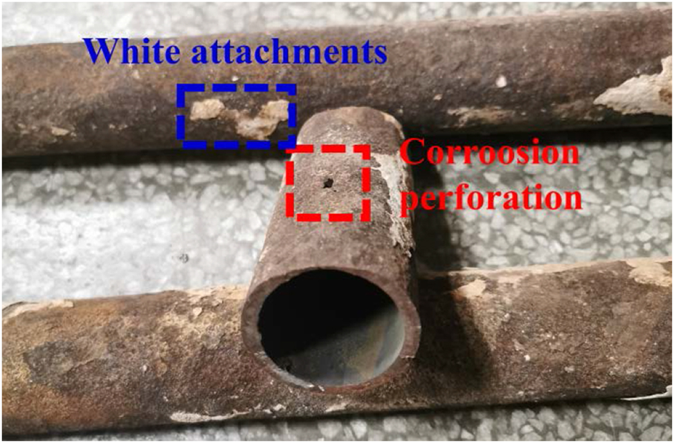
High-temperature superheater outlet serpentine tube for sample preparation.
A high-temperature corrosion test platform was established to reveal the corrosion perforation mechanism of the 12Cr1MoVG tube in the waste incineration boiler superheater, as shown in Figure 2. Incomplete combustion in waste incineration boilers led to the generation of CO and O2, while the decomposition of sulfur-containing substances produced high-temperature H2S gas. A mixed gas of 10 % CO–0.2 % H2S–0.5 % O2–89.3 % N2 was used to simulate the flue gas atmosphere of a waste incineration boiler, in which N2 serving as the protective gas. After thorough mixing in the gas mixer, the gas entered the corrosion test reaction reactor, with the temperature maintained at 500 °C. Subsequently, the exhaust gas passed through CuCl and NaOH solutions sequentially to absorb residual CO and H2S gases. The test samples were prepared into 12 mm × 12 mm × 2 mm coupons using wire cutting technology, which conformed to the specimen standards for high-temperature corrosion testing. These coupons were suspended in an alumina boat by an alumina rod to facilitate full contact and reaction with the mixed gas (Guo et al. 2022b). The coupons were divided into two groups, with one group coated with Na2SO4 solution and the other with NaCl solution on the surface, to simulate the deposition of sulfur- and chlorine-containing fly ash on the surface of waste incineration boiler tubes.
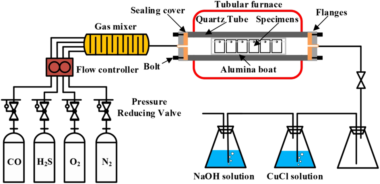
Corrosion test platform for simulating waste incineration.
The element content of the white attachments on the outer wall of the 12Cr1MoVG tube was analyzed using the S4 PIONEER X-ray fluorescence spectrometer (XFR). The elemental analysis range was Be4–U92, and the concentration range was from sub-ppm to 100 %. The phases present in the white attachments and corrosion products on both the 12Cr1MoVG tube and coupon were analyzed using the Empyrean X-ray diffractometer (XRD). The testing parameters were configured with a current of 40 mA and a voltage of 40 kV, and the scanning range was 20°–80°. The morphology of the corrosion products on both the 12Cr1MoVG tube and coupon was examined using the GeminiSEM 500 field emission scanning electron microscope (SEM). The acceleration voltage was set at 15 kV, with a resolution of 0.6 nm. An energy dispersive spectrometer (EDS) was employed to analyze the elemental distribution of the corrosion products (Guo et al. 2022a).
3 Results
3.1 Corrosion test of 12Cr1MoVG coupon
Figure 3 shows the corrosion kinetics curves of 12Cr1MoVG coupons at 500 °C. After exposure for 200 h, severe corrosion weight loss was observed on the 12Cr1MoVG coupons coated with Na2SO4. Compared with NaCl, Na2SO4 more prone to inducing brittle and uneven corrosion products on the 12Cr1MoVG steel, resulting in severe spalling of the corrosion layer. After corrosion by FeCl3 + HCl solution, the pearlite structure in 12Cr1MoVG steel could be clearly observed using an optical microscope, as shown in Figure 4a. Exposed to a mixed gas at 500 °C for 200 h, the corrosion products on the 12Cr1MoVG coupons coated with Na2SO4 and NaCl experienced severe peeling, as shown in Figure 4b. After the corrosion product peeled off, white particles were exposed on the 12Cr1MoVG coupons. The 12Cr1MoVG coupons coated with Na2SO4 and NaCl follow a parabolic-like corrosion kinetic law (Guo et al. 2023a). The 12Cr1MoVG coupons coated with Na2SO4 showed larger error bars, indicating more severe and uneven corrosion product detachment. XRD analysis showed that Fe2O3, Fe3O4, and FeS corrosion products were formed on the 12Cr1MoVG coupons coated with Na2SO4 and NaCl, as shown in Figure 5. The brittle Fe2O3 and FeS might cause large-scale peeling of the oxide film on 12Cr1MoVG coupons.
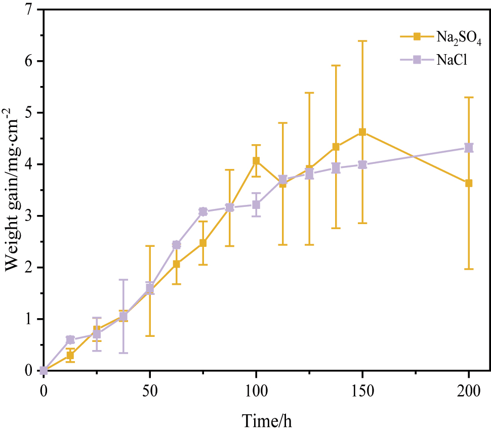
Corrosion kinetics of 12Cr1MoVG coupon at 500 °C.
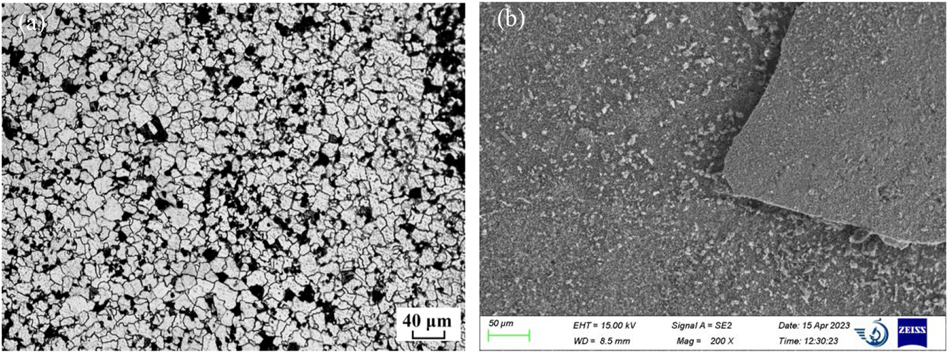
Microstructure of 12Cr1MoVG sample before and after corrosion test: (a) metallographic before corrosion and (b) morphology after corrosion.
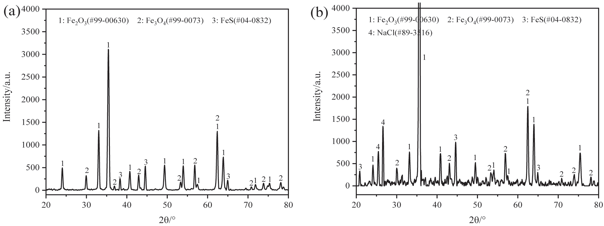
XRD analysis of corrosion production on 12Cr1MoVG coupon at 500 °C for 200 h: (a) Na2SO4 and (b) NaCl.
As shown in Figure 6a, the height of the corrosion layer on the 12Cr1MoVG coupon coated with Na2SO4 was 158 μm. The corrosion layer was mainly composed of uniformly distributed iron oxide and iron sulfide, in which obvious corrosion layer peeling was observed. The inner corrosion layer exhibited a loose multilayer structure, but the outer corrosion layer was relatively dense. The height of the corrosion layer on the 12Cr1MoVG coupon coated with NaCl was 57 μm, as shown in Figure 6b. The corrosion layer peeled off along the iron sulfide. The iron oxide and iron sulfide in the corrosion products underwent obvious stratification (Li et al. 2024). The outer layer of iron oxide appeared relatively dense, whereas the inner layer of iron sulfide exhibited numerous cracks and pores. Ion chloride was located at the surface of the corrosion layer, indicating limited diffusion of Cl ions from NaCl through the corrosion layer to the substrate. FeS resulting from the reaction between Na2SO4 and Fe was situated at the outer layer, while FeS generated from the reaction between H2S and Fe was located at the inner layer. The exfoliation of the corrosion layer on the 12Cr1MoVG coupons coated with Na2SO4 and NaCl were attributed to the brittleness and looseness of iron sulfide, but the formation of iron sulfide did not induce internal oxidation of the 12Cr1MoVG coupons.
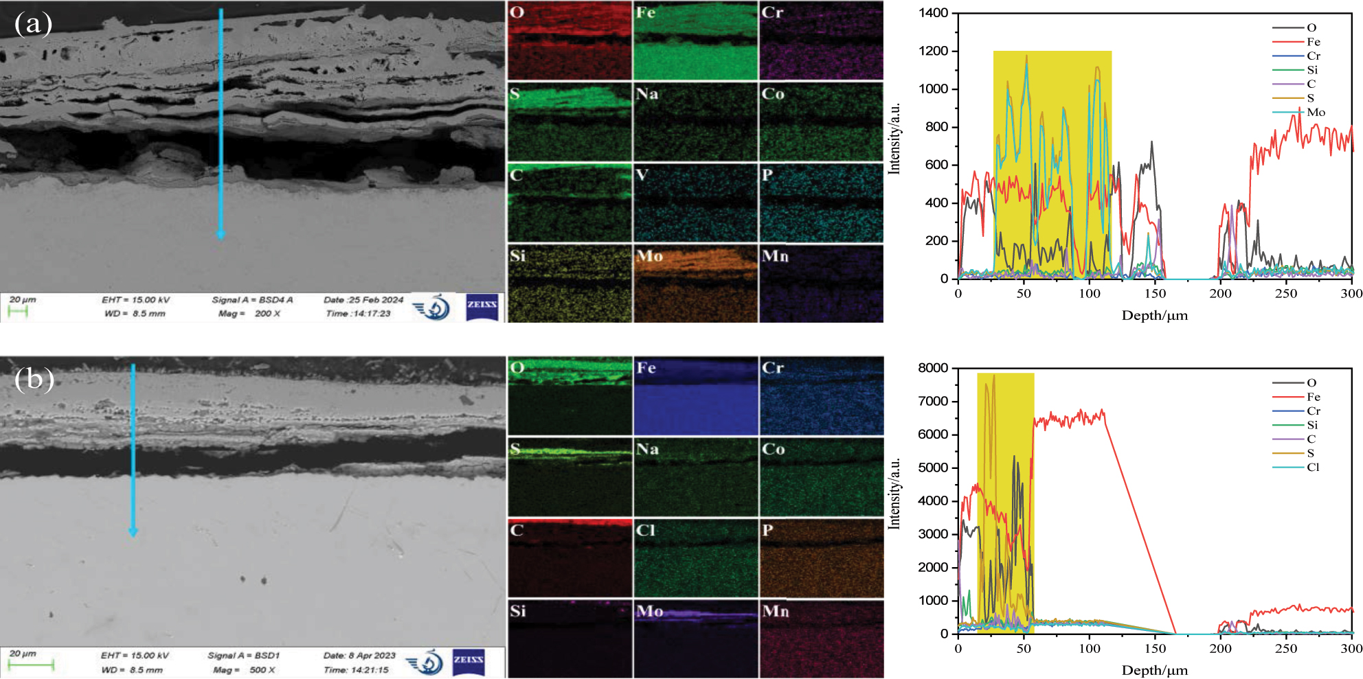
SEM and EDS analysis of the cross section of 12Cr1MoVG coupon at 500 °C for 200 h: (a) Na2SO4 and (b) NaCl.
3.2 12Cr1MoVG tube for actual boiler operation
Figure 7 shows the SEM and EDS analysis of corrosion production on 12Cr1MoVG tube. The elements O, S, K, and Ca in the white attachments were uniformly distributed, while the distribution of Fe was nonuniform, as shown Figure 7a. The EDS point scanning results showed that the Fe, S, and Cl contents in fine particles were 5.93 %, 15.49 %, and 4.01 %, while the Fe, S, and Cl contents in large particles were 25.90 %, 5.63 %, and 0.50 %. This indicated that the fine particles were sulfates and chlorides, while the large particles were iron oxides and iron sulfides peeled off from the outer wall of the 12Cr1MoVG tube. The nonuniform distribution of S and Cl elements could lead to uneven corrosion of 12Cr1MoVG tubes. The intensified localized corrosion of these tubes could result in stress concentration, eventually causing tube leakage. The XRF analysis results showed that the S and Cl contents in the powder were 11.5 % and 1.26 %, respectively, indicating high levels of sulfide and chloride in the white attachments on the outer wall of the tube contain, and the remaining components were mainly iron oxides. The contents of Zn and Pb were 0.47 % and 0.27 %, respectively, which came from the incineration of electronic waste. The formation of slag was attributed to the eutectic mixtures generated by ZnCl2 and PbCl2, which readily formed on relatively cooler surfaces of the high-temperature superheater. These corrosive products disrupted the generation of the oxide film and accelerated the corrosion of 12Cr1MoVG tube.
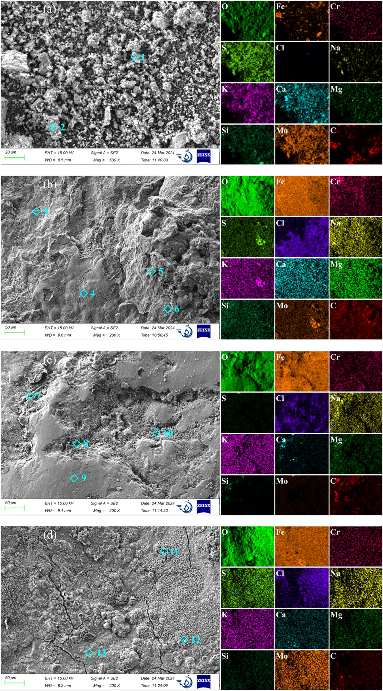
SEM and EDS analysis of corrosion production on 12Cr1MoVG tube: (a) attachment powder, (b) attachment zone, (c) thinning zone, and (d) smoothing zone.
In order to deeply explore the reasons for corrosion perforation of the 12Cr1MoVG tube, the surface morphology of the attachment zone, thinning zone, and smooth zone near the perforation was observed using SEM, as shown in Figure 7b–d. In the attachment zone on the outer wall of the 12Cr1MoVG tube, O and Fe elements were evenly distributed, while S and Cl elements were unevenly distributed. The maximum contents of S and Cl elements were measured through EDS point analysis to be 4.15 % and 3.84 %, respectively, indicating the deposition of sulfate salts and chloride salts from waste fuels in this area. The maximum contents of S and Cl elements in the thinning zone were 0.41 % and 1.97 %, respectively. As shown in Figure 7c, the decrease in S and Cl content indicated that FeS peels off along with the attachments, resulting in the thinning of the 12Cr1MoVG tube. In the smooth zone, the maximum contents of S and Cl elements were 0.71 % and 2.25 %, respectively, so FeS and FeCl2 were in the corrosion products. As shown in Figure 7d, cracks were generated in the corrosion products, leading to the subsequent peeling off of the corrosion layer.
The XRD analysis indicated that the white attachments included Fe2O3 oxide, FeS sulfide, as well as salts such as Na2SO4, KCl, and NaCl, consistent with the corrosion product composition revealed by XRF, as shown in Figure 8a (Meng et al. 2023; Zhang et al. 2020). As shown in Figure 8b, XRD analysis revealed that the corrosion products on the 12Cr1MoVG tube include Fe2O3, Fe3O4, FeS, and FeCl2 (Guo et al. 2023a). Combined with the XRD analysis results of the white attachments, the loose Fe2O3 and FeS on the 12CrMoVG tube peeled off together with the attachments.
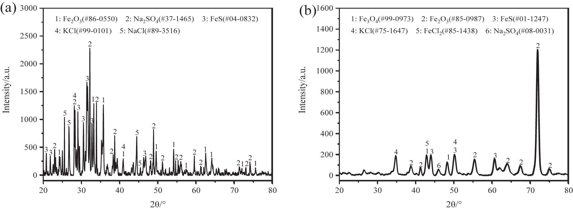
XRD analysis of corrosion production on 12Cr1MoVG tube: (a) attachment powder and (b) 12Cr1MoVG tube.
A nonuniform Fe3O4 layer was generated on the outer wall of the 12Cr1MoVG tube, as shown in Figure 9a. Combined with the XRD analysis, it was evident that the iron oxide layer was composed of Fe2O3 and Fe3O4. Enrichment of S and Cl was observed on the outer layer, and XRD showed that they were FeS and FeCl2. The depth of the internal oxidation was approximately 50 μm, in which many cracks and holes were observed, as shown in Figure 9b. Significant enrichment of Cl was distributed between the matrix and the internal oxide, indicating that Cl ions with strong penetration capability exacerbated the internal oxidation of the 12Cr1MoVG tube (Liu et al. 2024b).
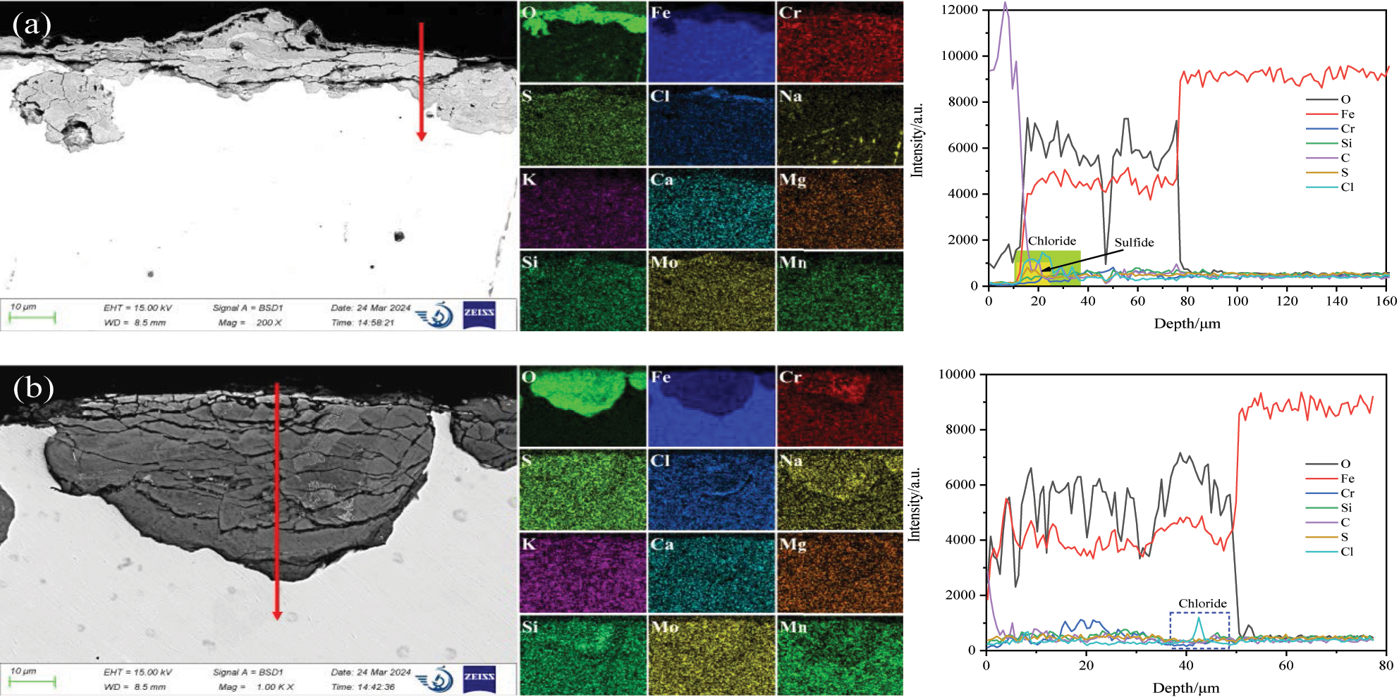
SEM and EDS analysis of the corrosion production on 12Cr1MoVG tube.
4 Discussion
Incineration of waste generated high-temperature gases, low-melting-point liquid molten salts, and high-melting-point solid dust particles (Verbinnen et al. 2018). High-temperature gases included HCl and H2S acidic corrosive gases. To resist the damage caused by these corrosive gases to the material substrate, an iron oxide layer was rapidly formed on 12Cr1MoVG tube. The Fe in the substrate reacted with O to form Fe2O3 and Fe3O4 oxides. Due to the low oxygen content in the corrosive gases, Fe3O4 oxide was predominantly formed. Fe3O4 oxide exhibited higher stability compared to Fe2O3 oxide at 500 °C. Therefore, an Fe3O4 oxide layer formed on the 12Cr1MoVG tube with a small amount of Fe2O3 oxide distributed. At 500 °C, the oxygen partial pressures required to form Fe2O3 and Fe3O4 oxides were 1.45 × 10⁻²⁸ atm and 9.44 × 10⁻³⁰ atm, respectively. Consequently, Fe2O3 was distributed near the gas side, while Fe3O4 was distributed near the substrate side (Guo et al. 2022a).
HCl reacted with O2 to form Cl2, which then reacted with Fe to form FeCl2 and FeCl3. FeCl2 could dissolve in low-melting-point eutectic mixtures, leading to the thinning of 12Cr1MoVG tube (Ma et al. 2020). The volatilization of FeCl3 with a boiling point of 316 °C destroyed the structure of the oxide film and created pathways for the diffusion of acidic corrosive gases. Additionally, Fe could react with H2S to form brittle FeS. Under the influence of thermal stress and flue gas purge, FeS was prone to peeling (Ebara et al. 2021). Although the formation of iron oxide film on 12Cr1MoVG tube could slow down the contact between acidic corrosive gases and the substrate, H2S could convert Fe2O3 into FeS, destroying the protective performance of the oxide film.
The liquid molten salts were mainly composed of low-melting-point PbCl2 and ZnCl2 chlorides. High-melting-point NaCl and KCl could combine with these molten salts to form low-melting-point eutectic mixtures. These liquid media could dissolve oxide films and greatly increased the corrosion rate of metal components at high temperatures (Galetz et al. 2014; Ma et al. 2017). Additionally, the dust was captured by the eutectic mixtures, next slagging appeared on the outside of the 12Cr1MoVG tube after cooling, as shown in Figure 1. The white attachments on the outside of the 12Cr1MoVG tube hindered the heat exchange, causing an increase in tube temperature and accelerating the corrosion of the 12Cr1MoVG tube.
High-melting-point solid particles included NaCl and KCl, as well as Ca and Si ashes. The reaction between NaCl and SO2 produces Na2SO4 (Liu et al. 2024b). As shown in Figure 9a, Na2SO4 reacted with Fe on the outer layer to produce brittle FeS, resulting in the thickening of the corrosion layer on the 12Cr1MoVG tube. FeCl2 was primarily formed from the reaction between Fe and Cl2. Chloride ions could penetrate the corrosion layer and reached the substrate surface, inducing severe internal oxidation of the 12Cr1MoVG tube (Li et al. 2023b). The reaction of NaCl and KCl with Fe produced smaller amounts of FeCl2, which was mainly distributed on the outer side of the corrosion layer. Therefore, the white attachments consisted of PbCl2, ZnCl2, Fe2O3, Fe3O4, FeCl2, FeS, KCl, NaCl, and Na2SO4.
The ReaxFF molecular dynamics (MD) was a powerful tool to simulate the dynamic evolution of atoms and chemical bonds during metal corrosion (Guo et al. 2023b). Although SO2 was not initially present in the gas mixture, some H2S would react with O2 to form SO2. This SO2 acted as an intermediate product and participated in the corrosion process of 12Cr1MoVG tube. Four MD models, Fe–Fe–SO2, Fe–O2, Fe–H2S, and Fe–CO were established. Chemical adsorption of the four gas molecules on the Fe surface was completed at 5 ps, and the reactions between Fe and the four gas molecules reached a stable phase at 1,000 ps, as shown in Figures 10–13. Initially, SO2 diffused toward the Fe surface, where S atoms from the SO2 molecules were chemically adsorbed on the Fe surface, as shown in Figure 10a (Guo et al. 2023c). Subsequently, an intense reaction phase between Fe and SO2 ensued, with S and O atoms rapidly diffusing into the Fe matrix. Ultimately, Fe oxides and Fe sulfides were formed on the Fe surface. Additionally, volatile iron sulfite or iron sulfide diffused from the Fe surface into the gas phase, as shown in Figure 10b. This process was challenging to observe with microscopic characterization equipment. Thermodynamic calculations proved that FeSO4 could be generated spontaneously. The reaction between Fe and O2 was highly intense, resulting in a relatively thick and continuous Fe oxide layer at 1,000 ps, as shown in Figure 11. In contrast, the reactions of Fe with H2S and CO were comparatively slower, with the stable adsorption state not yet fully disrupted at 1,000 ps, as shown in Figures 12 and 13.
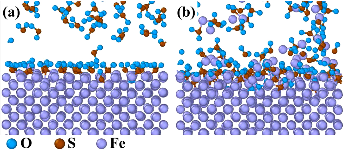
MD simulation results of the reaction between pure Fe and SO2: (a) 5 ps and (b) 1,000 ps.
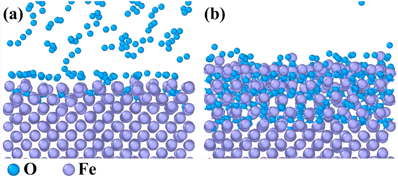
MD simulation results of the reaction between pure Fe and O2: (a) 5 ps and (b) 1,000 ps.
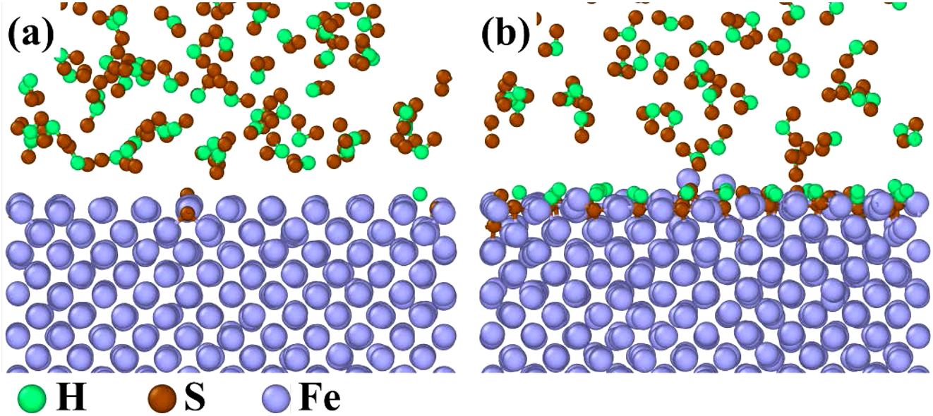
MD simulation results of the reaction between pure Fe and H2S: (a) 5 ps and (b) 1,000 ps.
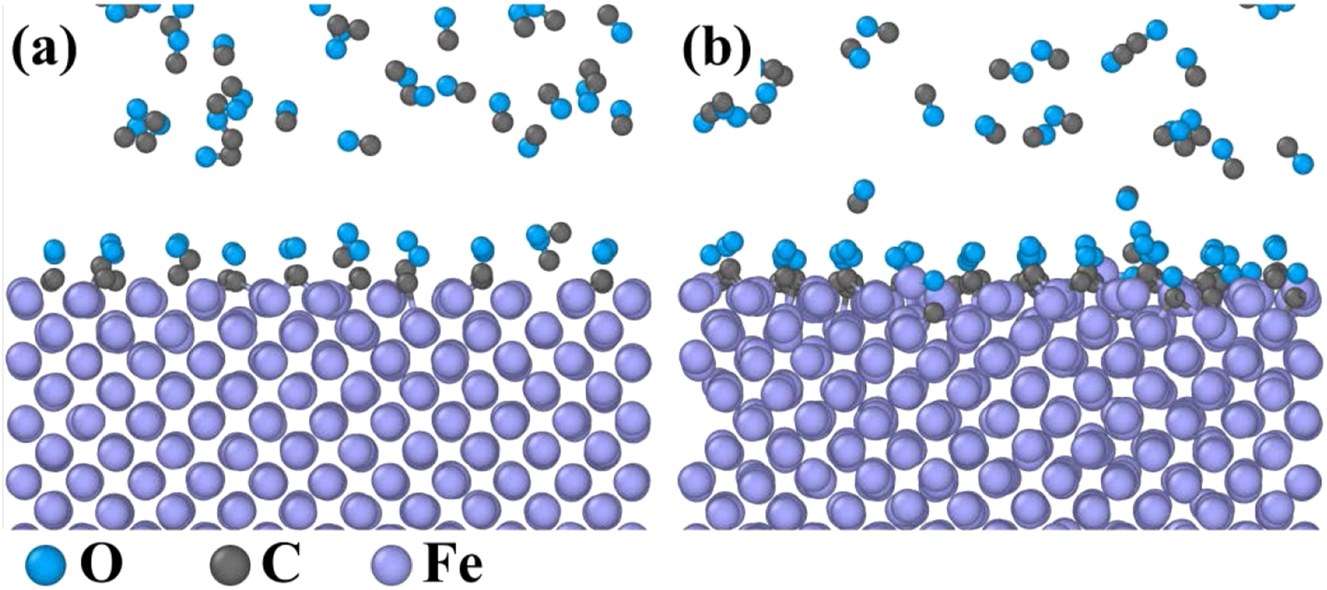
MD simulation results of the reaction between pure Fe and CO: (a) 5 ps and (b) 1,000 ps.
To verify the distribution rules of corrosion products, the thermodynamic phase diagram of Fe in S/O/Cl atmospheres at 500 °C was calculated using FactSage 8.0. Fe3O4 was located near the substrate side, while Fe2O3 was found near the gas side, as shown in Figure 14a (Guo et al. 2023a). When the partial pressure of O increased, Fe3O4 would transform into Fe2O3. However, FeCl2 could not form when the partial pressure of Cl2 was below 10−17 atm. When the partial pressure of Cl2 exceeded 10−17 atm, FeCl2 would form underneath the corrosion layer, as shown in Figure 14b and c. With increasing Cl2 partial pressure, Fe3O4 and FeS were converted to FeCl2. Consequently, the partial pressure of Cl on the 12Cr1MoVG coupon coated with NaCl was small, and it was difficult to generate FeCl2, as shown in Figure 6b. If the partial pressure of Cl2 in the acidic corrosive gases was high, FeCl2 would form underneath the corrosion layer, leading to severe internal oxidation of the 12Cr1MoVG tube, as shown in Figure 9b. Because of the elevated partial pressure of S in the acidic corrosive gases, brittle FeS could form on the 12Cr1MoVG coupon regardless of whether Na2SO4 was applied.
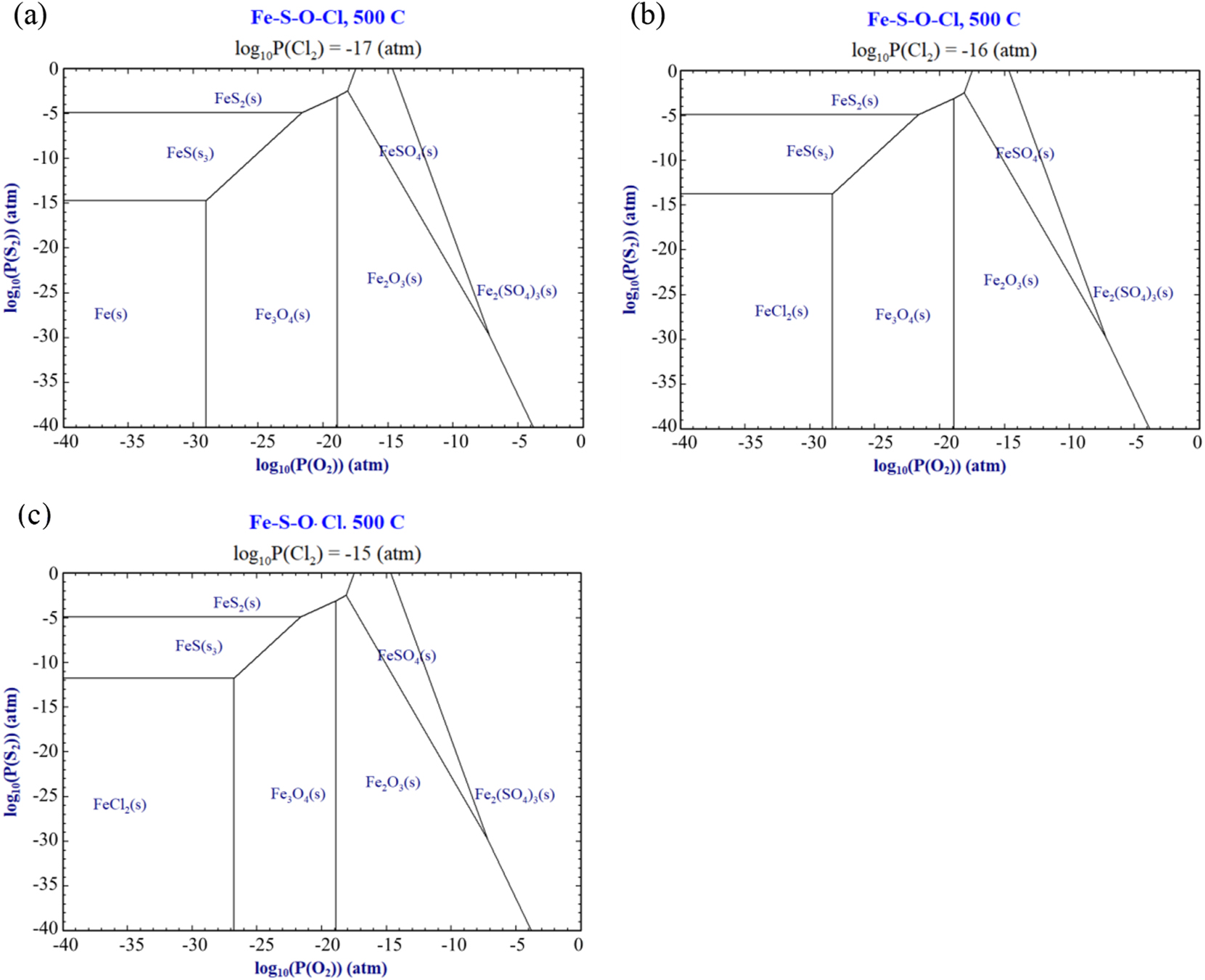
Phase diagram of corrosion products on Fe in S/O/Cl atmospheres.
Figure 15 shows the corrosion failure mechanism of 12Cr1MoVG tube in a waste incineration boiler. The incineration of waste produced high-temperature acidic corrosive gases, low-melting-point eutectic mixtures, and high-melting-point solid dust particles. As a result, 12Cr1MoVG tubes suffered from gas corrosion and the dissolution of molten salts. Additionally, slagging on the tube would also accelerate the corrosion of the 12Cr1MoVG steel. The Fe3O4 oxide layer and a small amount of reddish-brown Fe2O3 could be formed on both the flue gas side and the working fluid side of the 12Cr1MoVG tube in the waste incineration boiler. The Fe2O3 oxides were relatively loose and would peel off together with the attachments on the outside of the 12Cr1MoVG tube. The 12Cr1MoVG tube reacted with H2S to form FeS in the inner oxide layer, while the 12Cr1MoVG tube reacted with Na2SO4 to form FeS in the outer oxide layer (Paz et al. 2021). Due to the brittleness of FeS, it would peel off with the attachments on the outer side of the 12Cr1MoVG tube. The reaction of 12Cr1MoVG steel with Cl2 produced FeCl2, which dissolved in the low-melting-point eutectic mixture. Cl with strong penetrating ability could pass through the corrosion layer and reached the substrate surface (Zhang et al. 2004). Since FeCl2 was dissolved in the low-melting-point eutectic mixture, it provided a channel for O to diffuse into the substrate, resulting in severe internal oxidation of the 12Cr1MoVG tube. Eventually, under the influence of brittle FeS peeling, FeCl2 dissolution, and severe internal oxidation, corrosion perforation appeared in the 12Cr1MoVG tube. Next, the high-pressure working fluid leaked, causing the waste incineration boiler to be forced to shut down. The leakage of high-pressure working fluid caused serious harm to the safety and economy of the unit.
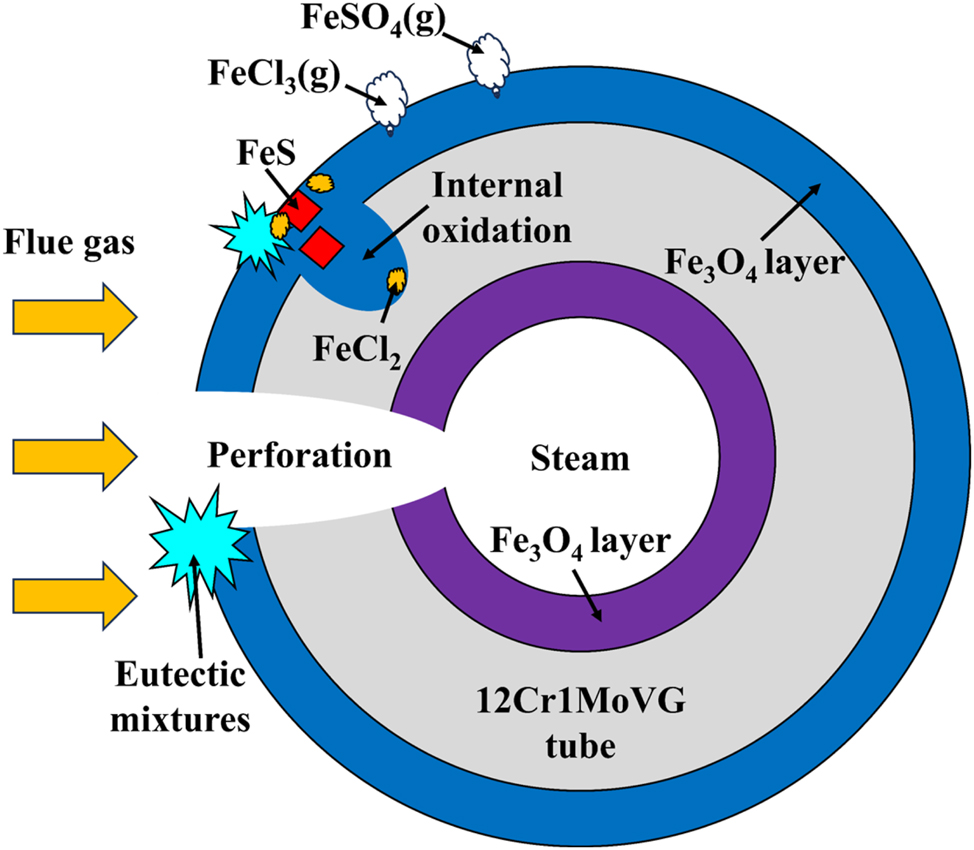
Corrosion failure mechanism of 12Cr1MoVG tube.
5 Conclusions
The 12Cr1MoVG tube of the waste incineration boiler superheater suffered from corrosion perforation under the influence of brittle Fe2O3 and FeS spalling, FeCl2 dissolution, FeCl3 and FeSO4 volatilization, and severe internal oxidation.
The attachments on the outer wall of the 12Cr1MoVG tube consisted of PbCl2, ZnCl2, Fe2O3, Fe3O4, FeCl2, FeS, KCl, NaCl, and Na2SO4, in which the S and Cl contents were 11.5 % and 1.26 %, respectively.
The brittle FeS produced by the reaction of 12Cr1MoVG tube with Na2SO4 and H2S was located in the outer layer and inner layer of the corrosion products, respectively, and it peeled off together with the attachments.
The low-melting-point eutectic mixture composed of PbCl2 and ZnCl2 could dissolve FeCl2, causing severe internal oxidation of 12Cr1Mo1VG tube. The volatilization of FeCl3 and FeSO4 destroyed the structure of the oxide film, so Cl could pass through the corrosion layer and reached the surface of the substrate.
Funding source: The National Natural Science Foundation of China
Award Identifier / Grant number: 52276015
Funding source: The China Postdoctoral Fund
Award Identifier / Grant number: 2020M683474
Acknowledgments
We thank Mr Ren Zijun at Instrument Analysis Center of Xi'an Jiaotong University for his assistance with SEM analysis.
-
Research ethics: The local Institutional Review Board deemed the study exempt from review.
-
Author contributions: The authors have accepted responsibility for the entire content of this manuscript and approved its submission.
-
Use of Large Language Models, AI and Machine Learning Tools: Corrosion failure analysis induced by S and Cl.
-
Conflict of interest: The authors state no conflict of interest.
-
Research funding: The National Natural Science Foundation of China (52276015) and the China Postdoctoral Fund (2020M683474) support this work. The Market Supervision and Management Science and Technology Plan Project of Anhui Provincial (2022MK053) support this work.
-
Data availability: The raw data can be obtained on request from the corresponding author.
References
Brunner, P.H. and Rechberger, H. (2015). Waste to energy-key element for sustainable waste management. Waste Manage. 37: 3–12, https://doi.org/10.1016/j.wasman.2014.02.003.Suche in Google Scholar PubMed
Ebara, R., Tanaka, F., and Kawasaki, M. (2021). Sulfuric acid dew point corrosion in waste heat boiler tube for copper smelting furnace. Eng. Fail. Anal. 33: 29–36, https://doi.org/10.1016/j.engfailanal.2013.04.007.Suche in Google Scholar
Galetz, M.C., Bauer, J.T., Schütze, M., Noguchi, M., Takatoh, C., and Cho, H. (2014). The influence of copper in ash deposits on the corrosion of boiler tube alloys for waste-to-energy plants. Mater. Corros. 65: 778–785, https://doi.org/10.1002/maco.201206787.Suche in Google Scholar
Ge, F., Wang, X., Meng, X., Huang, X., Zhang, Y., Song, Y., Ge, H., and Zhao, Y. (2021). Comparison of corrosion behavior of 2205 and 2507 duplex stainless steel in simulated flue gas condensate of a waste incineration power plant. Corros. Rev. 39: 477–486, https://doi.org/10.1515/corrrev-2021-0011.Suche in Google Scholar
Guo, T., Xu, Y., Liu, S., Liang, Z., and Zhao, Q. (2022a). Characteristics of the corrosion products on three scratched heat-resisting alloys in closed-loop supercritical and high-temperature CO2. Corros. Sci. 198: 110148, https://doi.org/10.1016/j.corsci.2022.110148.Suche in Google Scholar
Guo, T., Wang, M., Liang, Z., Shao, H., and Zhao, Q. (2022b). High-temperature corrosion behavior of T92, TP347HFG and IN625 with surface scratching in carbon dioxide at 600 °C. Oxid. Met. 97: 97–121, https://doi.org/10.1007/s11085-021-10078-z.Suche in Google Scholar
Guo, H., Fan, W., Long, J., and Liu, Y. (2023a). Influence of surface condition on the high-temperature corrosion of 12Cr1MoVG, T91, and TP347H steels in waste-to-energy boilers. Eng. Fail. Anal. 152: 107497, https://doi.org/10.1016/j.engfailanal.2023.107497.Suche in Google Scholar
Guo, T., Cao, X., Shao, H., Zhao, Q., and Liang, Z. (2023b). Effect of Fe on the oxidation, sulfidation and carburization behaviors of alloys in CO2 containing SO2. Corros. Sci. 222: 111438, https://doi.org/10.1016/j.corsci.2023.111438.Suche in Google Scholar
Guo, T., Wu, H., Shao, H., Zhao, Q., and Liang, Z. (2023c). Revealing the role of SO2 in the high-temperature corrosion diffusion of two superalloys in CO2 through molecular dynamics and thermal stability. J. Alloy Compd. 948: 169746, https://doi.org/10.1016/j.jallcom.2023.169746.Suche in Google Scholar
Kawahara, Y. (1997). Development and application of high-temperature corrosion-resistant materials and coatings for advanced waste-to-energy plants. Mater. High. Temp. 14: 261–268, https://doi.org/10.1080/09603409.1997.11689552.Suche in Google Scholar
Kawahara, Y., Orita, N., Takahashi, K., and Nakagawa, Y. (2001). Demonstration test of new corrosion-resistant boiler tube materials in high efficiency waste incineration plant. Tetsu. To. Hagane. 87: 544–551, https://doi.org/10.2355/tetsutohagane1955.87.8_544.Suche in Google Scholar
Lee, S.H., Themelis, N.J., and Castaidi, M.J. (2007). High-temperature corrosion in waste-to-energy boilers. J. Therm. Spray. Tech. 16: 104–110, https://doi.org/10.1007/s11666-006-9005-4.Suche in Google Scholar
Li, Y., Zhao, X., Li, Y., and Li, X. (2015). Waste incineration industry and development policies in China. Waste Manage. 46: 234–241, https://doi.org/10.1016/j.wasman.2015.08.008.Suche in Google Scholar PubMed
Li, H., Liu, H., Bai, M., Zhang, X., Chi, H., Chen, T., Yu, Y., and Yao, H. (2023a). Insight into the corrosion resistance of Mo-added NiCrBSi coating in simulated waste incineration environment. Corros. Sci. 216: 111085, https://doi.org/10.1016/j.corsci.2023.111085.Suche in Google Scholar
Li, J., Liu, Z., Ma, H., Wang, X., Kong, Y., Li, Y., and Shen, Y. (2023b). High-temperature corrosion behavior of C276 alloy, 1.4529 steel and laser-cladding 1.4529 coating under the synergistic action of deposited chloride salt and HCl-containing atmosphere. Corros. Sci. 222: 111413, https://doi.org/10.1016/j.corsci.2023.111413.Suche in Google Scholar
Li, H., Liu, H., Huang, Y., Chen, X., Zhang, X., Li, J., Xu, L., and Yao, H. (2024). Mechanism of coupling corrosion caused by flue gas and deposits in municipal solid waste incinerator: roles of H2O(g), HCl, and SO2. Corros. Sci. 231: 111933, https://doi.org/10.1016/j.corsci.2024.111933.Suche in Google Scholar
Liu, X., Duan, Y., Zheng, L., Long, L., Khalid, Z., Huang, Q., and Jiang, X. (2024a). High-temperature corrosion mechanism analysis of 310S alloy in typical MSWI flue gas environment at 460–580 °C. J. Mater. Cycles Waste. 26: 197–212, https://doi.org/10.1007/s10163-023-01812-7.Suche in Google Scholar
Liu, X., Duan, Y., Zheng, L., Long, L., Khalid, Z., Huang, Q., and Jiang, X. (2024b). Effect of complex municipal solid waste incineration flue gas on the corrosion of various alloys at 550 °C. Fuel 355: 129524, https://doi.org/10.1016/j.fuel.2023.129524.Suche in Google Scholar
Lu, J., Zhang, S., Hai, J., and Lei, M. (2017). Status and perspectives of municipal solid waste incineration in China: a comparison with developed regions. Waste Manage. 69: 170–186, https://doi.org/10.1016/j.wasman.2017.04.014.Suche in Google Scholar PubMed
Ma, W., Wenga, T., Zhang, N., Chen, G., Yan, B., Zhou, Z., and Wu, X. (2017). Full-scale experimental investigation of deposition and corrosion of pre-protector and 3rd superheater in a waste incineration plant. Sci. Rep. 7: 17549, https://doi.org/10.1038/s41598-017-17438-3.Suche in Google Scholar PubMed PubMed Central
Ma, W., Wenga, T., Frandsen, F.J., Yan, B., and Chen, G. (2020). The fate of chlorine during MSW incineration: vaporization, transformation, deposition, corrosion and remedies. Prog. Energ. Combust. 76: 100789, https://doi.org/10.1016/j.pecs.2019.100789.Suche in Google Scholar
Makarichi, L., Jutidamrongphan, W., and Techato, K.A. (2018). The evolution of waste-to-energy incineration: a review. Renew. Sust. Eenerg. Rev. 91: 812–821, https://doi.org/10.1016/j.rser.2018.04.088.Suche in Google Scholar
Meng, X., Lv, G., Zheng, L., Hu, J., and Jiang, X. (2023). Analysis of formation and growth process of ash deposition on the convective heating surface of a 400 t/d MSW incinerator based on different operating days. Energ. Source Part A. 45: 10616–10632, https://doi.org/10.1080/15567036.2023.2248038.Suche in Google Scholar
Montgomery, M., Hansson, A.N., Jensen, S.A., Vilhelmsen, T., and Nielsen, N.H. (2013). In situ corrosion testing of various nickel alloys at Mabjerg waste incineration plant. Mater. Corros. 64: 14–25, https://doi.org/10.1002/maco.201006019.Suche in Google Scholar
Mudgal, D., Ahuja, L., Singh, S., and Prakash, S. (2016). Evaluation of corrosion performance of Superni 600 hung in secondary chamber of medical waste incinerator operating at 1050 °C. Mater. High. Temp. 34: 45–52, https://doi.org/10.1080/09603409.2016.1234663.Suche in Google Scholar
Nabavi, P.A., Bayat, R., Hosseinzadeh, B.H., Afrasyabi, H., and Chau, K.W. (2017). Modeling of energy consumption and environmental life cycle assessment for incineration and landfill systems of municipal solid waste management: a case study in Tehran Metropolis of Iran. J. Clean. Prod. 148: 427–440.10.1016/j.jclepro.2017.01.172Suche in Google Scholar
Nanda, S. and Berruti, F. (2016). A technical review of bioenergy and resource recovery from municipal solid waste. J. Hazard. Mater. 403: 123970, https://doi.org/10.1016/j.jhazmat.2020.123970.Suche in Google Scholar PubMed
Ouda, O.K.M., Raza, S.A., Nizami, A.S., Rehan, M., Al-Waked, R., and Korres, N.E. (2016). Waste to energy potential: a case study of Saudi Arabia. Renew. Sust. Energ. Rev. 61: 328–340, https://doi.org/10.1016/j.rser.2016.04.005.Suche in Google Scholar
Pastén, M.S. and Spiegel, M. (2006). High temperature corrosion of metallic materials in simulated waste incineration environments at 300 °C–600 °C. Mater. Corros. 57: 192–195.10.1002/maco.200503909Suche in Google Scholar
Paz, M.D., Phother-Simon, J., Andersson, S., and Jonsson, T. (2021). High temperature corrosion memory in a waste fired boiler-influence of sulfur. Waste Manage. 130: 30–37, https://doi.org/10.1016/j.wasman.2021.05.005.Suche in Google Scholar PubMed
Pedersen, A.J., Frandsen, F.J., Riber, C., Astrup, T., Thomsen, S.N., Lundtorp, K., and Mortensen, L.F. (2009). A full-scale study on the partitioning of trace elements in municipal solid waste incineration-effects of firing different waste types. Energy Fuels 23: 3475–3489, https://doi.org/10.1021/ef801030p.Suche in Google Scholar
Pérez, F.J., Hierro, M.P., and Nieto, J. (2008). Waste incineration corrosion processes: oxidation mechanisms by electrochemical impedance spectroscopy. Mater. Corros. 59: 566–572, https://doi.org/10.1002/maco.200804139.Suche in Google Scholar
Pettersson, R., Flyg, J., and Viklund, P. (2008). Materials performance in simulated waste combustion environments. Corros. Eng. Sci. Techn. 43: 123–128, https://doi.org/10.1179/174327808x286365.Suche in Google Scholar
Samolada, M.C. and Zabaniotou, A.A. (2014). Comparative assessment of municipal sewage sludge incineration, gasification and pyrolysis for a sustainable sludge-to-energy management in Greece. Waste Manage. 34: 411–420, https://doi.org/10.1016/j.wasman.2013.11.003.Suche in Google Scholar PubMed
Tan, S.T., Ho, W.S., Hashim, H., Lee, C.T., Taib, M.R., and Ho, C.S. (2015). Energy, economic and environmental (3E) analysis of waste-to-energy (WTE) strategies for municipal solid waste (MSW) management in Malaysia. Energ. Convers. Manage. 102: 111–120, https://doi.org/10.1016/j.enconman.2015.02.010.Suche in Google Scholar
Verbinnen, B., De Greef, J., and Van Caneghem, J. (2018). Theory and practice of corrosion related to ashes and deposits in a WtE boiler. Waste Manage. 73: 307–312, https://doi.org/10.1016/j.wasman.2017.11.031.Suche in Google Scholar PubMed
Villarruel, M.A., Reinhart, D., and Sohn, Y. (2022). Incinerator ash characterization-implications for elevated temperature landfills. Waste Manage. 153: 72–80.10.1016/j.wasman.2022.08.017Suche in Google Scholar PubMed
Yan, Z., Wang, L., Li, X., Wei, J., Liu, C., and Da, Y. (2022). Failure mechanism of superheater tubes of waste heat boiler for waste incineration in complex environment. Eng. Fail. Anal. 139: 106457, https://doi.org/10.1016/j.engfailanal.2022.106457.Suche in Google Scholar
Yi, S., Lin, H., Abed, A.M., Shawabkeh, A., Marefati, M., and Deifalla, A. (2023). Sustainability and exergoeconomic assessments of a new MSW-to-energy incineration multi-generation process integrated with the concentrating solar collector, alkaline electrolyzer, and a reverse osmosis unit. Sustain. Cities. Soc. 91: 104412, https://doi.org/10.1016/j.scs.2023.104412.Suche in Google Scholar
Zhang, K., Niu, Y., Zeng, C., and Wu, W. (2004). Corrosion of iron and four commercial steels in a Cl-containing oxidizing atmosphere at 500–600 °C. J. Mater. Sci. Technol. 20: 213–216.Suche in Google Scholar
Zhang, Y., Du, X., Yue, M., Yan, M., and Shi, Y. (2020). Heat transfer and ash deposition performance of heat exchange surface in waste incineration flue gas. Int. J. Heat Mass Tran. 155: 119691, https://doi.org/10.1016/j.ijheatmasstransfer.2020.119691.Suche in Google Scholar
Zhang, X., Liu, H., Chen, T., Li, H., Huang, Z., Yu, Y., and Yao, H. (2023). Mechanism of coupling corrosion caused by flue gas and deposits in municipal solid waste incinerator: resistance of HVOF-NiCr coating. Fuel 342: 127845, https://doi.org/10.1016/j.fuel.2023.127845.Suche in Google Scholar
© 2024 the author(s), published by De Gruyter, Berlin/Boston
This work is licensed under the Creative Commons Attribution 4.0 International License.
Artikel in diesem Heft
- Frontmatter
- Reviews
- Biomacromolecules as green corrosion inhibitors: a review based on mild steel corrosion in acidic media
- Copper corrosion mechanisms, influencing factors, and mitigation strategies for water circuits of heat exchangers: critical review and current advances
- Original Articles
- Influence of corrosion inhibitors on aging mechanism of epoxy resin coatings for copper 62 alloy in simulated marine environment
- High tribo-corrosion resistance of Ni-Cr-5Al2O3 thermal spray coating: a comparison of post processing techniques
- Understanding the role of S and Cl degrading the corrosion resistance of 12Cr1MoVG steel in a waste incineration boiler: on-site and laboratory testing