Structural function analysis of shear walls in sustainable assembled buildings under finite element model
-
Yaxian Cao


Abstract
With the quick progress of industrialization and urbanization, the construction industry has become one of the largest energy-consuming industries. However, the current prefabricated shear wall focuses on the upgrade of seismic function, with less analysis of the energy efficiency of the overall structure. In this study, a sustainable prefabricated building shear wall that takes into account both energy conservation and stress is first proposed, and then the shear wall is modelled by finite element method (FEM) software. Meanwhile, the force functions of the shear wall model, including concrete strength, axial condensability rate, and aspect rate, and finally the seismic function are verified. The experimental outcomes demonstrate that the maximum difference between the FEM analysis outcomes and the test data is only 10.66%, and the overall difference in the outcomes is relatively small. The larger the aspect rate of the proposed sustainable assembled shear wall model, the better the ductility of the member, and the bigger the axial condensability rate and concrete strength, the lower the ductility of the member. In the seismic function analysis, the maximum layer displacement angles of this shear wall are all less than 1/120, which is in line with the national seismic code. This indicates its good seismic function and provides a methodological reference for the upgrade of the structural function of shear walls.
1 Introduction
Assembled construction is one of the achievements of residential industrialization and building industrialization. It can reduce environmental pollution during construction and greatly shorten the construction cycle, and has a broad development prospect in modern structural buildings [1]. This type of building includes modern timber structures, steel structures, and assembled concrete structures, of which prefabricated assembled concrete structures are the most widely used in construction projects and are gradually becoming the focus of research in this field. At present, the research on assembled shear walls focuses on the seismic resistance of the structure as a whole and the analysis of the force function at the connection nodes, to some extent neglecting the upgrade of energy efficiency [2]. With the continuous development of computer science and technology, finite element numerical analysis is widely used for construction engineering. It has great potential for use in mechanical engineering, petrochemical, and energy industries [3]. Therefore, the sustainable prefabricated shear wall structure is first proposed in the study, and the wallboard model is established through Midas finite element analysis (FEA) finite element software. Then, the parametric analysis is carried out, and the influence of each parameter on the mechanical performance of the model is summarized. Finally, the seismic performance is evaluated to provide theoretical and technical support for the design and performance analysis of the shear wall structure.
2 Related works
The analysis of the structural function of assembled shear walls is one of the main focuses of current research in construction engineering. With the continuous progress of modern technology, related professionals have got many achievements in this area and obtained many milestones. In order to study the seismic performance of composite shear walls, Su et al. [4] designed a new type of columnar stiffened concrete-filled steel tubular frame-inclined bar composite shear wall to develop high-efficiency stress-resistant components of high-rise buildings. The results show that its bearing capacity, damage, stiffness, energy consumption and deformation are significantly improved, and the calculated results of the finite element model are in good agreement with the experimental results. Dowden et al. [5] addressed the potential test problem of using bolted connections between the boundary members of steel sheet shear walls and punching padding panels in. Based on an analysis of the advantages of perforated infill sheets, i.e. their ability to be refined to minimize the forces for sheet connectors and ambient frontier component, combined with bolted connections for overall format of steel sheet shear walls, this method provides better seismic and hysteretic function compared to steel sheet shear walls with conventional solid infill sheets using welded connections. Guo and Wang [6] addressed the issue of shear-bearing capacity shear walls of Axial load precast-reinforced concrete, which is difficult to meet, and developed a new prefabricated shear wall located on the ground floor of a tower block in a violent earthquake zone based on the introduction of high ductility concealed columns and X-shaped steel sheet supports, which demonstrated widely distributed cracks and upgraded load-carrying capacity in quasi-static loading tests. Jya et al. [7] conducted shear wall repair on the structural performance of two single span and two story steel plates using non welded inclined stiffeners, and conducted quasi-static loading to simulate damage caused by earthquakes. The results showed that it effectively suppressed the residual out of plane deformation of the filler plate, and further proved that using inclined multi rib stiffeners is the most effective method to improve bearing capacity and suppress out of plane deformation of the filler plate. Labibzadeh et al. [8] designed a new type of shear wall composed of three corrugated steel plates filled with concrete to analyze the influence of opening shape and aspect ratio on the shear bearing capacity of a three-layer laminated steel plate concrete composite shear wall. The results showed that the bearing capacity of this new type of shear wall was 16% and 12% higher than that of a regular composite wall.
Khan and Yan [9] used the finite element software ABAQUS to analyse the nonlinear structural performance of the new type of joints under quasi-static and static cyclic loads, and carried out parametric analysis on the gap between adjacent modules and the length of the column tenon. The results showed that the gap between the upper and lower parts of the joints led to the failure of the floor beam. Wang and Wang [10] established the shear wall element software through ABAQUS FEM based on the mechanical properties of prefabricated steel plates, and carried out the construction of shear walls through nonlinear finite element analysis method. The results verify the effectiveness of this method. Jba et al. [11] developed a lateral force-based steel sheet shear wall framing system based on lateral forces, which was developed by shear spring and Buckling spring to simulate the behaviour of steel sheets shear walls. The outcomes demonstrated that it optimized the seismic function and obtained almost the same function parameters as the refined FEM. Mahmoud and Salman [12] evaluated the earthquake reaction of architecture with reinforced concrete shear walls of different storeys by investigating the displacement, shear force, bending moment, and inter-storey displacement as function indicators and demonstrated that it reduced the induced seismic response and cost. Msa et al. [13] proposed a combination of interior wall structure and composite system to address the low efficiency of existing shear wall systems in low rise buildings, and utilized advanced modeling programs for system design. The results showed that this design demonstrated high application efficiency in low rise buildings. Zhang et al. [14] designed a new type of prefabricated energy dissipation shear wall structure system, which connects adjacent wall panels with mild steel dampers at the vertical joints, and analysed and compared the vulnerability curve and seismic response under earthquake sequence and single main earthquake. The outcomes proved the feasibility and reliability of the shear wall.
In summary, most researchers have optimized the anti-seismic function of shear walls in their system and structure, and have demonstrated the effectiveness of the proposed methods in simulation experiments. However, the degree of application for finite elements is not sufficient and there are still problems such as low efficiency. The study therefore aims to analyse the function of sustainable assembled building wall structures by establishing an FEM under which they could be a reference for structural design.
3 Sustainable assembled building wall structures under FEM
3.1 FEM of sustainably assembled wall panels
The Midas FEA finite element simulation and analysis software is a non-linear detailed analysis finite element software specially designed for the civil engineering profession [15]. The pre-processing step is to build the FEM and the solution calculation is to carry out numerical calculations on the completed model, while the post-processing part is to output the calculation outcomes. The Midas FEA solution calculation defines the solution process through linear coupled equations and includes two solution methods: direct and iterative [16]. The iterative method is generally used for structural models with a large number of solid units and requires a long computational time, while the direct method can be used for a wide range of models, but requires a larger amount of computer memory. At the same time, the post-processing capabilities of Midas FEA are very powerful, allowing the output of detailed diagrams of the outcomes of various calculations and the ability to find the required units and specific node stresses in the software [17]. Therefore, the study uses this software to model the assembled wall panels. According to the specification, the thickness of the short leg shear wall shall not be less than 200 mm, and the ratio of the height of the wall section to the thickness is 5–8. The section structure of the shear wall model of the sustainable prefabricated building studied and designed is the middle insulation layer and the structural layers on both sides. The shear wall panel wall is 2,000 mm wide, the wall thickness is 200 mm, and the edge member length is 150 mm. The specific structure and reinforcement form of the sustainable prefabricated shear wall is demonstrated in Figure 1.

Concrete structure and reinforcement form of sustainable prefabricated shear wall.
The reinforcement units of the sustainable assembled shear wall model were created using reinforcing beam units within the beam unit of the program itself, while solid units were used in the concrete section [18]. For the force analysis of the reinforced concrete structure, the concrete solid cell has a built-in reinforcement cell, as the respective stresses of the concrete and the reinforcement are the focus of the analysis, so the bond slip between the two is ignored [19]. Midas FEA has a variety of meshing methods, with mapped meshing and automatic meshing being the two main ones. Among them, mapped meshing has a clear force transmission path and a uniform mesh form, and the shear wall model proposed in the study is relatively regular in shape, so this method is chosen for meshing. The smaller the mesh size, the more accurate the outcomes of the FEA calculations and the more accurate the force analysis will be, and the corresponding time and memory required for the calculations will be greater, so a suitable mesh size for the model must be chosen [20]. The mesh size of the reinforcing steel cells proposed in the study are all 50 mm, while for the concrete cells the mesh size is determined by their geometrical function. The grid widths of the sustainable assembled shear wall sections proposed in the study are all 50 mm, with 65 mm on both sides and 70 mm in the middle of the grid length. For the boundary conditions of the model, fixed constraints are added to the bottom of the wall slab model, constraining its degrees of freedom to six directions. The difference between the experimental outcomes obtained from the construction of reciprocally loaded or monotonically loaded shear walls is small, and the reciprocal loading will lead to changes in the material ontology model, which affects the simulation accuracy of the finite element analysis, so the horizontal monotonic loading and vertical fixed loading regimes are used for processing.
3.2 Concrete material ontological relationships
Concrete is an engineering composite material in which aggregates are cemented together by the action of cementitious materials. The composite materials of concrete are diverse, which leads to uneven materials and complex Constitutive equation [21]. In finite element analysis, the selection and setting of the concrete material instantonal relationship determine the level of detail and accuracy of the analysis, and the selection of the appropriate material instantonal relationship is crucial to the accuracy of the outcomes of the whole procedure. The Midas FEA material library has a wide range of concrete crack models, including expansion crack models, total strain crack models, linear elastic crack models, and discrete crack models [22]. The total strain cracking model is a discrete cracking model based on the elastic behaviour of the material cracking as defined by elastic damage and simulates concrete in a non-linear state of behaviour through isotropic hardening in condensability and elastic cracking in tension. The model can be divided into a rotating model, where the crack always follows the direction of the principal strain, and a fixed model, where the crack direction does not change [23]. The fixed model can provide a specific description of the physical function of the crack, but the definition of structural strength and stiffness is too large. The rotating model does not require the physical function of the crack to be preserved, is simpler to calculate in structural analysis, and is highly convergent, so it is used for non-linear calculations of reinforced concrete structures [24]. The concrete material is characterized by each isotropy before the crack occurs and each anisotropy afterwards, so the concrete material is defined in Midas FEA by orthogonal anisotropy and then the shear and normal stresses of the crack are calculated, the characteristics of which are demonstrated in Figure 2.

Orthogonal crack model.
In Midas FEA, if lateral restraint occurs when concrete is compressed, then the various homogeneous stresses are amplified, as is the stiffness of the structure [25]. The factors influencing the stress–strain in concrete under condensability are the extreme strain and the value of the extreme stress. The damage function determines the magnitude of these two factors and the damage function is at the same time a function of the transverse restraint stress in the structure. In the event of cracks in the structure along the vertical direction of pressure, both the extreme strain and extreme stress values decrease and the expression for the model’s stressed region is demonstrated in the following equation:
In Eq. (1),
In Eq. (2),
In Eq. (3),
In Eq. (4),
In Eq. (5),
In Eq. (6),

Geometric dimension and reinforcement drawing of member section.
4 Analysis of performance outcomes of assembled shear wall under finite element model
First, to validate the accuracy of the model and the adopted principal structure relationship, three sets of material tests were conducted on the reinforcing steel and concrete materials used, respectively. The concrete was C40 and the measured values of the cubic compressive strength in the material mechanical function were 55.2, 49.96, and 52.1 N/mm2, with an average value of 52.42 N/mm2, and the modulus of elasticity of 3.25 × 10⁴ N/mm2; the mechanical indexes of reinforcement are demonstrated in Table 1.
Mechanical index of reinforcement
| Rebar specification | Elastic modulus (× 105 N/mm2) | Average value | Ultimate strength (N/mm2) | Average value | Yield strength (N/mm2) | Average value |
|---|---|---|---|---|---|---|
| D6.5 | 1.78 | 1.86 | 651.67 | 645.58 | 499.28 | 512.14 |
| 2.07 | 643.51 | 494.68 | ||||
| 1.72 | 641.56 | 542.17 | ||||
| D12 | 1.65 | 1.64 | 570.30 | 561.45 | 423.60 | 426.20 |
| 1.66 | 561.05 | 429.70 | ||||
| 1.61 | 533.01 | 422.20 |
Finite element simulations were carried out and compared with experimental data to verify the model and the intrinsic structure relationship under the defined mechanical specifications of concrete function and the mechanical specifications of steel function demonstrated in Table 1, the outcomes of which are demonstrated in Figure 4.
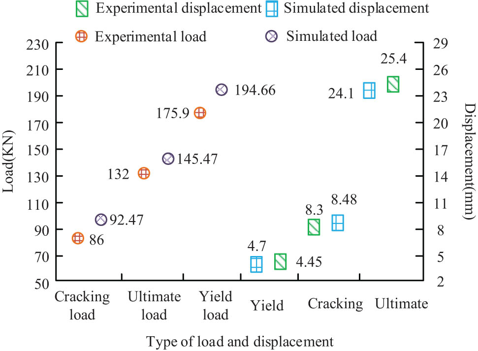
Comparison outcomes of finite element calculation and test data.
In Figure 4, the experimental data are 1.25% smaller than the outcomes under the FEM for the wall slab cracking load. For cracking displacement, the experimental data are 5.32% larger than the outcomes from the FE because the concrete diffuse cracking simulates the non-linear behaviour of concrete through condensability isotropic hardening elastic–plastic and tension elastic cracking, causing the analysis to be more rigid. For yield loads and yield displacements, the difference is 10.38 and 2.17%, respectively. In the comparison of ultimate load and ultimate displacement, the FE data differed by 10.66 and 5.12%, respectively. Therefore, the outcomes of the FE only partially deviated from the test data, and the overall damage trend was basically the same, indicating that the method of defining the material intrinsic model and the FEM used were accurate. The shear wall slab force function was then analysed using three shear wall models with different aspect rate, named SW1 (1.5), SW2 (2.0), and SW3 (2.5), all with axial condensability rate of 0.5, vertical and transverse reinforcement rate of 0.393%, all built to a thickness of 200 mm, a width of 2,000 mm, and heights of 3,000, 4,000, and 5,000 mm, respectively. The outcomes of the non-linear analysis in the finite element software for the three shear wall models with different aspect rates are demonstrated in Figure 5.

Nonlinear analysis outcomes of three shear wall models with different rates of height to width in finite element software.
In Figure 5, the force state of the shear wall model at different periods is greatly influenced by the aspect rate. When the top displacements are the same, the horizontal bearing capacity of the member gradually decreases as the aspect rate increases. The top horizontal displacement increases with increasing height rate when the top loads are equal, thus indicating that the greater the aspect rate, the better the ductility of the shear wall element. At the same time, the slope of the load displacement curve during the increasing phase increases as the height rate of the shear wall decreases. Once the ultimate load is exceeded, the absolute value of the slope of the load displacement curve in the decreasing phase increases and the member demonstrates brittle damage. The effect of different axial pressure rates on the structural function of the proposed shear wall models was then analysed in finite element software. Four groups of shear wall models with axial pressure rates of 0.1, 0.3, 0.5, and 0.7, corresponding to the names SW4, SW5, SW2, and SW6, were designed, all with member height of 4,000 mm, member width of 2,000 mm, thickness of 200 mm, horizontal and vertical reinforcement ratios are both 0.393. The non-linear finite element analysis is implemented for the four shear wall models with various axial condensability rates, and the load–deflection outcomes are demonstrated in Figure 6.

Load–displacement outcomes of four shear wall models with different axial condensability rates.
In Figure 6, the overall variation of load–deflection curve obtained from the shear wall model with various axial pressure rates is small at the beginning of loading, and as the axial pressure rate raises, the gradient of load–deflection curve in the rising phase is greater, while the axial pressure rate of the member is positively related to the peak load. When the load–deflection curve is in the decreasing phase, the decreasing trend of the model becomes steeper with the addition of axial pressure rate. The reason for this is that the relative compressive height of the section raises as the member’s axial pressure rate raises, and the higher the axial pressure rate, the higher the ultimate load-carrying capacity and the lower the ductility. The outcomes of the displacement and load comparisons for shear walls with various axial condensability rates are demonstrated in Figure 7.
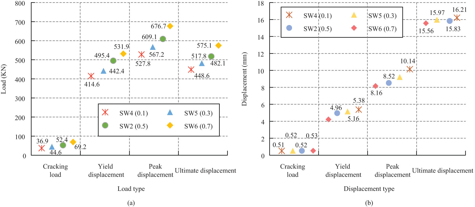
Comparison outcomes of various displacements and loads of shear walls under different axial condensability rates. (a) Comparison of various loads of shear walls with different axial compression ratios and (b) comparison of various displacements of shear walls with different axial compression ratios.
In Figure 7, the cracking load of the members increased slightly with the increase of the axial pressure rate, indicating that the cracking of the shear wall could be retarded by increasing the axial pressure rate; the yield load of SW4 was 27.77 kN lower than that of SW5, the yield load of SW6 was increased by 52.27 kN compared with SW2, and SW2 was 35.21 kN higher than that of SW5, indicating that the yield load of the shear wall increased continuously with the increase of the axial pressure rate. And the increase is also greater, especially when the axial condensability rate exceeds 0.5, the peak load and yield load appear to increase significantly. At the same time, the cracking displacement of SW4 is the smallest and that of SW6 is the largest, with a difference of only 0.2 mm between the two, indicating that the cracking displacement of the member is less affected by the axial pressure rate. As the axial pressure rate increases, the ultimate displacement, peak displacement, and yield displacement of the model all decrease. When the axial pressure rate of the model increases, the displacement angle becomes smaller, indicating that its ductility function is worse. Therefore, at a certain other parameter of the shear wall element, the horizontal bearing capacity increases with increasing axial pressure rate and the ductility function becomes worse. The effect of different concrete strengths on the function of the proposed shear wall elements is then investigated. C30 (SW2-1), C40 (SW7-1), C50 (SW8-1) and C30 (SW2-2), C40 (SW7-2), and C50 (SW8-2) are used to define the constitutive relationship of model concrete, with an axial pressure rate of 0.5 and a model aspect rate of 2.0, respectively, and the outcoming load–displacement curves for different concrete strengths are demonstrated in Figure 8.

Load–displacement curve under different concrete strength. (a) Load displacement curve of SW2-1, SW7-1, and SW8-1 and (b) load displacement curve of SW2-2, SW7-2, and SW8-2.
In Figure 8, the load–displacement curves of SW2-1 and SW2-2, SW7-1 and SW7-2, and SW8-1 and SW8-2 differ greatly, thus meaning that the force state of the shear wall is greatly influenced by the strength of concrete. Meanwhile, as the concrete strength continues to raise, the initial stiffness of the construction gradually increases and there is a significant increase in ultimate and peak loads. Finally, the seismic function of the proposed sustainable assembled building shear walls was analysed for seismic waves of E1 Centro Site and Mexico City Station 1, with seismic directions X and Y. The outcomes of the comparison of the average maximum inter-storey displacement angle per storey for the 24-storey shear wall residential model under the two seismic waveforms are demonstrated in Figure 9.
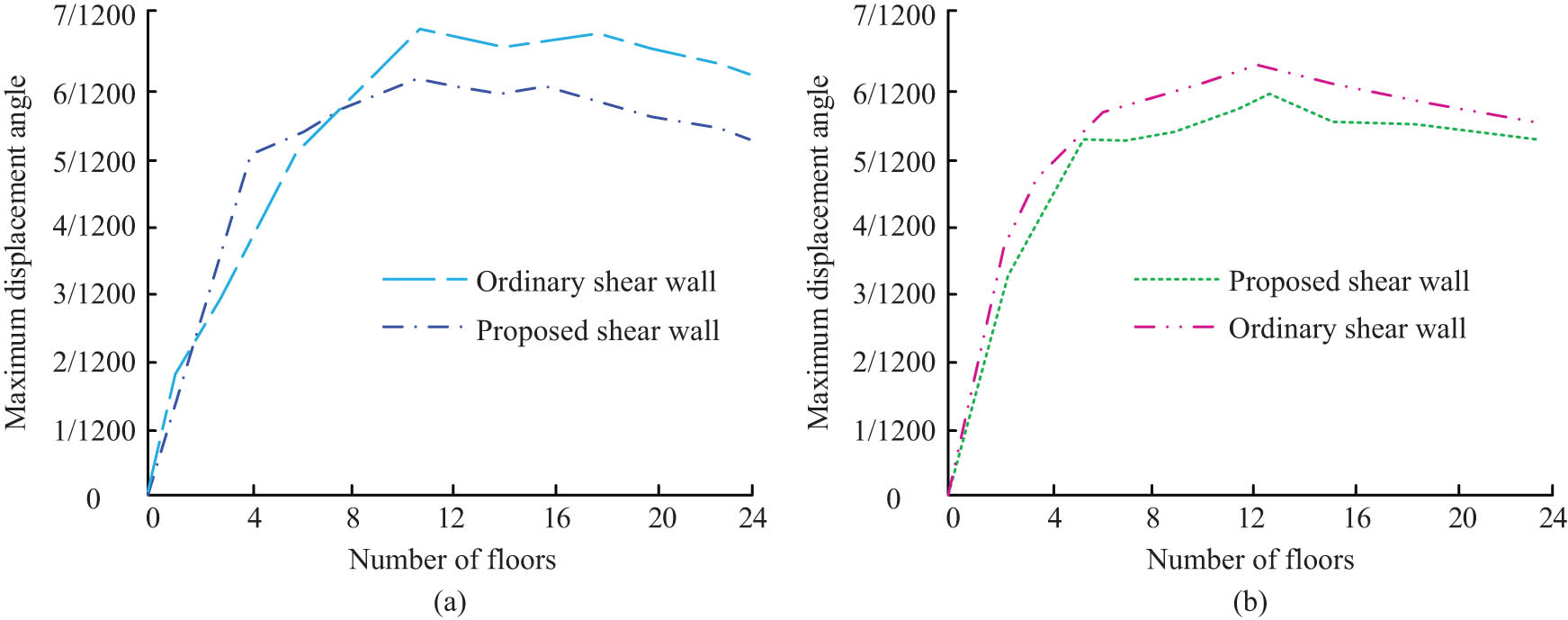
Comparison of the maximum inter story displacement angle between the proposed shear wall and the ordinary shear wall. (a) X direction and (b) Y direction.
Figure 9 (a) and (b) demonstrates the comparative outcomes of the inter-storey displacement angles of the conventional shear wall and the new shear wall in the X-direction and Y-direction separately. In Figure 8, the maximum inter-storey displacement angles of both shear walls occur near the twelfth storey, both in the X-direction and in the Y-direction, and the displacement angles of the proposed shear wall at all storeys are slightly smaller than those of the ordinary shear wall. At the same time, the maximum storey displacement angles of the proposed shear walls satisfy the national seismic code, i.e., the maximum storey displacement angles are all less than 1/120, indicating that the shear walls upgrade the seismic function to some extent while satisfying the national seismic code.
5 Conclusions
The development of assembled shear walls is of great importance for the construction of modern structural buildings. The research’s foundation is assembling concrete structures and the development of sustainable assembled shear walls. It consists of an insulation layer and a structural layer, with concrete and lightweight insulation as the main components, respectively. An FEM of the wall panel and the concrete material ontological relationship was then developed and finite element analysis of its force function and seismic capacity was carried out. The outcomes demonstrate that with the increase of axial compression ratio, the cracking load of members increases slightly. The yield load of SW4 is 27.77 kN lower than that of SW5. The yield load of SW6 is 52.27 kN higher than that of SW2. The yield load of SW2 is 35.21 kN higher than that of SW5. Meanwhile, the crack displacement of SW4 is the smallest, and that of SW6 is the largest. The difference between the two is only 0.2 mm. Compared with the test data, the minimum difference between the results obtained by the FEM is 1.25%, and the maximum difference is 10.66%, which is consistent overall. It indicates that the reliability of the method is high. In the non-linear analysis of the four parameters of aspect rate, concrete strength, and axial condensability rate, it was concluded that concrete strength and axial condensability rate have an inverse trend with shear wall ductility function and aspect rate has a positive trend with shear wall ductility function. In the analysis of dynamic time, the mean maximum inter-storey displacement angle of the model is smaller than the code limit of 1/120 for all storeys and has a good seismic function. However, in the analysis of the force function, there is a lack of consideration of parameters in the form of horizontal reinforcement rate and cavity size, so further investigation is required in this area.
-
Funding information: The author states no funding involved.
-
Conflict of interest: Author states no conflict of interest.
References
[1] Kosari E, Poursha M, Abedi K. Seismic evaluation of tall unstiffened steel sheet shear wall (SPSW) systems with emphasis on reversal phenomenon in the higher mode pushover curve. Int J Civ Eng Trans a Civ Eng. 2019;17(5):523–40.10.1007/s40999-018-0286-zSearch in Google Scholar
[2] Patel N, Jamle S. Use of shear wall belt at optimum height to increase lateral load handling capacity in multistory building: A review. Int J Res Eng Appl Manag. 2019;4(10):596–603.10.22161/ijaers.6.4.36Search in Google Scholar
[3] Gholhaki M, Karimi M, Pachideh G. Investigation of subpanel size effect on behavior factor of stiffened steel sheet shear wall. J Struct Constr Eng. 2019;5(4):73–87.Search in Google Scholar
[4] Su H, Zhu L, Wang Y. Experimental study and finite-element analysis of shear wall with CFST, column-form reinforcement, and diagonal bars. Steel Comp Struct An Int J. 2021;4:41–3.Search in Google Scholar
[5] Dowden DM, Bruneau M. Shake table testing of perforated steel sheet shear wall having light gauge bolted infill panels. J Constr Steel Res. 2022;13:188–91.10.1016/j.jcsr.2021.107030Search in Google Scholar
[6] Guo S, Wang M. Seismic behavior of an innovative equivalent monolithic precast shear wall under low and high axial load rates. Structures. 2022;39(2):444–69.10.1016/j.istruc.2022.03.048Search in Google Scholar
[7] Yu J, He L, Li B, Li L, Tian L, Men J. Structural behaviour of post-earthquake steel sheet shear wall repaired by non-welded oblique stiffeners. Structures. 2022;39(6):70–85.10.1016/j.istruc.2022.03.029Search in Google Scholar
[8] Labibzadeh M, Bagheri M, Khademalrasoul A, Hossain KMA. An investigation of the effects of aspect rate and opening on CSPSW and TSCSW. Int J Struct Integr. 2022;13(3):411–47.10.1108/IJSI-01-2022-0004Search in Google Scholar
[9] Khan K, Yan JB. Finite element analysis on seismic behaviour of novel joint in prefabricated modular steel building. Int J Steel Struct. 2020;20(3):752–65.10.1007/s13296-020-00320-wSearch in Google Scholar
[10] Wang Y, Wang ZC. Finite element analysis of the mechanical properties of prefabricated composite shear-wall with fishplate connection. Acad J Manuf Eng. 2020;18(4):87–99.Search in Google Scholar
[11] Bai J, Zhang J, Jin S, Wang YH. A simplified computational model for seismic function evaluation of steel sheet shear wall-frame structural systems. Structures. 2021;33(17):1677–89.10.1016/j.istruc.2021.05.049Search in Google Scholar
[12] Mahmoud S, Salman A. Impact of shear wall design on function and cost of RC buildings in moderate seismic regions. Earthq Struct. 2021;21(5):489–503.Search in Google Scholar
[13] Salameh M, Shayanfar M, Barkhordari MA. Estimation and development of innovative hybrid coupled shear wall system using nonlinear dynamic and fragility analysis. Structures. 2020;26(3):703–23.10.1016/j.istruc.2020.04.031Search in Google Scholar
[14] Zhang H, Li C, Wang ZF, Zhang CY. Seismic function assessments of precast energy dissipation shear wall structures under earthquake sequence excitations. Earthq Struct. 2020;18(2):147–62.Search in Google Scholar
[15] Bai J, Zhang J, Du K, Jin S. A simplified seismic design method for low-rise dual frame-steel sheet shear wall structures. Steel Comp Struct An Int J. 2020;37(4):34–48.Search in Google Scholar
[16] Jiang H, Huang Y, He L, Huang T, Zhang S. Seismic function of RC frame-shear wall structures with vertical setback. Structures. 2021;33:4203–17.10.1016/j.istruc.2021.07.018Search in Google Scholar
[17] Barkhordari MS, Es-haghi MS. Straightforward prediction for responses of the concrete shear wall buildings subject to ground motions using machine learning algorithms. Int J Eng. 2021;34(7):1586–601.10.5829/ije.2021.34.07a.04Search in Google Scholar
[18] Chong X, Sha H, Xie L, Li A, Jiang Q, He Y et al. Experimental and numerical studies on the seismic function of precast concrete shear wall structures with an energy dissipation cladding panel. J Earthq Eng. 2022;26(6):3264–79.10.1080/13632469.2020.1796843Search in Google Scholar
[19] El-Sokkary H, Elsharawy M. Impact of revised seismic hazard values in NBCC 2015 on RC shear wall buildings. J Arc Eng. 2022;3:28–31.10.1061/(ASCE)AE.1943-5568.0000547Search in Google Scholar
[20] Ma W, Xu K, Cheng B, Zhang Y, Chen R, Chen D. Experimental study on the seismic behavior of a new single-faced superposed shear wall with the concealed column. Structures. 2021;33:4446–60.10.1016/j.istruc.2021.07.033Search in Google Scholar
[21] Yang B, Zhang B, Wu J, Liu B, Wang Z. A BIM-based quantity calculation framework for frame-shear wall structure. Struct Eng Int. 2019;29(2):282–91.10.1080/10168664.2018.1550352Search in Google Scholar
[22] Carrero T, Montaño J, Berwart S, Santa María H, Guindos P. Seismic behavior of innovative hybrid CLT-steel shear wall for mid-rise buildings. Bull Earthq Eng. 2021;19(14):5917–51.10.1007/s10518-021-01204-ySearch in Google Scholar
[23] Bypour M, Kioumarsi B, Kioumarsi M. Investigation of failure mechanism of thin steel sheet shear wall in RC frame. Key Eng Mater. 2019;803:314–21.10.4028/www.scientific.net/KEM.803.314Search in Google Scholar
[24] Mahmoud S. In-plane shear-wall configuraten effects on the seismic function of symmetrical multistory reinforced-concrete buildings. Int J Civ Eng. 2021;19(10):1195–208.10.1007/s40999-021-00634-8Search in Google Scholar
[25] Fares AM. The effect of shear wall positions on the seismic response of frame-wall structures. Int J Civ Environ Eng. 2019;13(3):190–4.Search in Google Scholar
[26] Najm HM, Ibrahim AM, Sabri MMS, Hassan A, Morkhade S, Mashaan NS et al. Evaluation and numerical investigations of the cyclic behavior of smart composite steel–concrete shear wall: comprehensive study of finite element model. Materials. 2022;15(13):4496–9.10.3390/ma15134496Search in Google Scholar PubMed PubMed Central
[27] Tan JK, Su MN, Wang YH, Wang K, Cao YQ, Li P. Experimental study on cyclic shear function of steel sheet shear wall with different buckling restraints. Structures. 2022;35:469–82.10.1016/j.istruc.2021.11.021Search in Google Scholar
© 2023 the author(s), published by De Gruyter
This work is licensed under the Creative Commons Attribution 4.0 International License.
Articles in the same Issue
- Research Articles
- Investigation of differential shrinkage stresses in a revolution shell structure due to the evolving parameters of concrete
- Multiphysics analysis for fluid–structure interaction of blood biological flow inside three-dimensional artery
- MD-based study on the deformation process of engineered Ni–Al core–shell nanowires: Toward an understanding underlying deformation mechanisms
- Experimental measurement and numerical predictions of thickness variation and transverse stresses in a concrete ring
- Studying the effect of embedded length strength of concrete and diameter of anchor on shear performance between old and new concrete
- Evaluation of static responses for layered composite arches
- Nonlocal state-space strain gradient wave propagation of magneto thermo piezoelectric functionally graded nanobeam
- Numerical study of the FRP-concrete bond behavior under thermal variations
- Parametric study of retrofitted reinforced concrete columns with steel cages and predicting load distribution and compressive stress in columns using machine learning algorithms
- Application of soft computing in estimating primary crack spacing of reinforced concrete structures
- Identification of crack location in metallic biomaterial cantilever beam subjected to moving load base on central difference approximation
- Numerical investigations of two vibrating cylinders in uniform flow using overset mesh
- Performance analysis on the structure of the bracket mounting for hybrid converter kit: Finite-element approach
- A new finite-element procedure for vibration analysis of FGP sandwich plates resting on Kerr foundation
- Strength analysis of marine biaxial warp-knitted glass fabrics as composite laminations for ship material
- Analysis of a thick cylindrical FGM pressure vessel with variable parameters using thermoelasticity
- Structural function analysis of shear walls in sustainable assembled buildings under finite element model
- In-plane nonlinear postbuckling and buckling analysis of Lee’s frame using absolute nodal coordinate formulation
- Optimization of structural parameters and numerical simulation of stress field of composite crucible based on the indirect coupling method
- Numerical study on crushing damage and energy absorption of multi-cell glass fibre-reinforced composite panel: Application to the crash absorber design of tsunami lifeboat
- Stripped and layered fabrication of minimal surface tectonics using parametric algorithms
- A methodological approach for detecting multiple faults in wind turbine blades based on vibration signals and machine learning
- Influence of the selection of different construction materials on the stress–strain state of the track
- A coupled hygro-elastic 3D model for steady-state analysis of functionally graded plates and shells
- Comparative study of shell element formulations as NLFE parameters to forecast structural crashworthiness
- A size-dependent 3D solution of functionally graded shallow nanoshells
- Special Issue: The 2nd Thematic Symposium - Integrity of Mechanical Structure and Material - Part I
- Correlation between lamina directions and the mechanical characteristics of laminated bamboo composite for ship structure
- Reliability-based assessment of ship hull girder ultimate strength
- Finite element method on topology optimization applied to laminate composite of fuselage structure
- Dynamic response of high-speed craft bottom panels subjected to slamming loadings
- Effect of pitting corrosion position to the strength of ship bottom plate in grounding incident
- Antiballistic material, testing, and procedures of curved-layered objects: A systematic review and current milestone
- Thin-walled cylindrical shells in engineering designs and critical infrastructures: A systematic review based on the loading response
- Laminar Rayleigh–Benard convection in a closed square field with meshless radial basis function method
- Determination of cryogenic temperature loads for finite-element model of LNG bunkering ship under LNG release accident
- Roundness and slenderness effects on the dynamic characteristics of spar-type floating offshore wind turbine