Experimental and numerical study on the axial compression behavior of circular concrete columns confined by BFRP spirals and ties
-
Muhammad Sufian
 ,
Mohamed F.M. Fahmy
,
Mohamed F.M. Fahmy

Abstract
This study investigates the compression behavior of circular concrete columns confined with basalt fiber-reinforced polymer (BFRP) stirrups, comparing their performance with traditional steel-reinforced columns. The objective of the study is to assess the impact of the BFRP transverse reinforcements and concrete mix design (CMD) codes on the compressive strength (CS), energy accumulation (GAcc), fracture energy (GF), and ductility of RC cylinders. A total of 81 reinforced concrete (RC) cylinders were prepared using three distinct CMD codes and tested under axial compression. The specimens were confined with 6 mm and 8 mm BFRP and steel spirals/ties at varying rib spacings (45 mm, 60 mm, and 90 mm). The experimental results revealed that closer BFRP spiral/tie spacings (45 mm) significantly enhanced the CS by 7–15 % and GAcc by up to 59 % of the columns due to improved confinement effect, compared to those with larger spacings (60 mm and 90 mm). BFRP ties demonstrated superior performance in terms of CS, GAcc, and GF compared to BFRP spirals, particularly at moderate and larger spacings. Finite element model (FEM) simulations validated the experimental results with less than 8 % deviation and demonstrate a high degree of correlation between predicted and observed failure behaviors. The study suggests that BFRP spirals/ties reinforcements with optimal spacing can effectively replace steel in structural applications, offering comparable performance in strength, ductility, and energy absorption. These findings encourage the use of BFRP-based reinforcements in durable, lightweight, and eco-friendly concrete constructions.
1 Introduction
Reinforced concrete (RC) structures are a vital part of contemporary construction. For this reason, structural safety relies heavily on the durability and quality of reinforcements, as well as concrete’s ability to withstand degradation. Numerous research projects aim to enhance RC structural components’ quality and performance, addressing the corrosion vulnerability of steel reinforcements as a significant issue causing deterioration and reduced lifespan. This issue has encouraged researchers to find substitute materials and techniques that can enhance the mechanical performance of RC structures. Abundant studies have investigated the possible uses of various FRPs as reinforcement to improve concrete mechanical performance in harsh conditions. A study suggested that reinforcing with GFRP spirals and bars can be viable alternatives in column design. The steel-reinforced and glass fiber-reinforced polymer (GFRP) columns exhibited comparable behavior, although the use of compacted GFRP spirals improved ductility [1]. Similarly, an attempt was made to replace steel spirals with GFRP spirals to reduce corrosion of steel bars in columns, as GFRP spirals have demonstrated durability in resisting chloride-induced corrosion while maintaining identical load-carrying capacity [2]. The ductility and deformation capacity of hybrid RC columns were improved by GFRP in certain studies; however, the same studies revealed variations in structural performance depending on factors like reinforcement type and quantity, cross-section, and spacing of bars and spirals [3], 4]. These studies highlighted the potential of GFRP as a replacement for steel in structural applications.
Previously, researchers investigated the application of composite systems that optimize the advantages of steel with FRP. A study validated the efficacy of FRP tube columns having FRP-steel composite bars, making them suitable for deployment in marine and coastal structures exposed to severe environments [5]. The compressive performance of columns reinforced with carbon fiber-reinforced polymer (CFRP) bars and spirals was investigated. Steel and CFRP reinforced columns showed similar behavior until peak loads and CFRP bars remained effective in resisting load after concrete crushing [6]. Another study reported that CFRP-reinforced beams offered higher load-carrying capability and performed similarly to steel-reinforced beams, concerning the reinforcement type and the shear reinforcement ratio [7]. The ductility of hybrid cylinders was significantly improved by employing compacted CFRP stirrups, whereas the initial stiffness was slightly affected [8]. A study suggested that combining steel and FRP can enhance the strength and deformation capacity of columns with the number of external FRP layers and close stirrup spacing [9]. The better confinement offered by FRP spirals and longitudinal bars resulted in higher load capacity and deformation capabilities. These results were validated by additional research, which also emphasized the significance of spiral pitch and the FRP reinforcement ratio in optimizing the performance of concrete columns [10], [11], [12], [13]. The use of various FRPs and composite systems for concrete reinforcement is a rapidly developing method. For instance, a study highlighted the importance of hybrid reinforcing methods in enhancing post-peak performance, a topic further explored with BFRP reinforcements. The use of crumb rubber and recycled steel fibers significantly enhanced energy absorption and slab toughness [14]. The significance of structural dimensions and material strength was highlighted by a recent study that examined the load bearing capacity and ductility of RC stub columns, using a hybrid reinforcing method [15]. Previous studies have utilized CFRP reinforcement and hybrid systems in various configurations as a substitute for traditional steel reinforcement to enhance structural performance and mitigate steel corrosion, a major factor contributing to structural failure.
Researchers are persistently investigating the possible uses of new fiber reinforced polymers like BFRP as reinforcement to improve concrete’s mechanical performance and durability. BFRP reinforcements are novel and environmentally sustainable alternatives to conventional reinforcement materials, including CFRP and GFRP. Exploring the mechanical behavior and confinement efficiency of BFRP reinforcements is essential for achieving their full potential. A novel coral reef sand concrete column strengthened with BFRP bars and spirals exhibited ductile behavior with closely spaced stirrups, indicating enhancements in post-peak performance. It was suggested that BFRP spirals and bars in columns can have the potential to enhance maritime durability and sustainability [16]. Similarly, the compressive performance of BFRP seawater sea-sand columns was investigated. It was found that decreasing tie spacing led to an increase in columns’ CS, attributed to the confinement effect. Moreover, the increased confinement effect and thicker bar size postponed the BFRP bars buckling and increased the ultimate strain in bars [17]. Another study introduced a computational model to predict the behavior of BFRP longitudinal reinforcement and stirrups in tubular columns. The results showed that stirrup spacing and BFRP bar thickness optimize the structural performance of columns [18]. Furthermore, a study found that the compressive and tensile modulus of BFRP bars is identical, and decreasing the spiral spacing can efficiently limit the deformation of the longitudinal BFRP bars, consequently enhancing the strength of structural components [19].
Several investigations about the impact of BFRP reinforcement on the compression behavior of columns have revealed that confinement efficiency, ductility, and load-carrying capacity are influenced by factors such as column size, reinforcement ratio, and cross-sectional configuration [20], [21], [22], [23]. A study revealed that BFRP ties effectively improve column structural integrity while retaining load-bearing capacity [24]. Another study reported a notable size effect on the strength, corresponding strain, and rate of deterioration of the concrete core. Moreover, the increase in transverse reinforcement ratio also improved load-carrying capability and ductility [25]. The shear performance of BFRP-reinforced beams was found to be more affected by the shear span-to-depth ratio than by stirrup spacing [26]. A hybrid reinforcement system (BFRP-steel) enhanced ductility and strength [27]. The hybrid columns’ load-bearing capacity, residual deformation, and energy dissipation were all significantly impacted by the longitudinal reinforcement’s post-yield stiffness [28]. The confinement efficiency and ductility of BFRP RC columns were enhanced with the reduction in the BFRP tie spacing. In addition, the BFRP RC columns showed similar bar strength contributions, and confinement efficiency as steel-reinforced columns [29]. It was revealed that the static stiffness, energy absorption, and shear ductility of BFRP RC beams improved with an increase in the stirrup ratio [30]. Furthermore, research has demonstrated that BFRP reinforcement can offer better resistance and durability by examining how BFRP-reinforced columns behave under harsh circumstances, such as high-energy impacts or seismic occurrences [31], 32].
In addition to the literature, BFRP is being studied as an alternative reinforcing material in concrete constructions to improve structural performance under different loading circumstances. GFRP and BFRP columns offered equal load-carrying capacities, although being less than steel-reinforced columns [33]. The application of BFRP geopolymer sea-sand concrete (GSSC) components in marine environments was explored. It was found that BFRP-GSSC columns and beams had greater ultimate capacities than their steel-reinforced equivalents and the addition of expansion agents and high reinforcement ratios enhanced the structural performance further [34]. Similar to this, low-modulus BFRP spirals effectively delayed buckling and enhanced the post-yield compressive behavior of structural concrete, as demonstrated by the compressive behavior of steel-FRP composite bars [35]. Another research revealed that BFRP can offer a feasible substitute for steel in key structural applications such as bridge piers and piles. The BFRP-reinforced columns offered equivalent strength to steel, with improved post-peak performance [36]. The impact resistance of BFRP stirrups and bars coupled with synthetic fibers reinforced geopolymer concrete (GPC) beams was investigated. BFRP-GPC beams had higher impact resistance, peak stresses, absorbed energy, and deflection capacity. Thus, BFRP reinforcement enhances impact resistance and structural integrity, especially when paired with fibers [37].
The literature study highlighted the use of FRPs like GFRP, CFRP, and BFRP as steel alternatives in RC structures. These investigations demonstrated that FRP reinforcements can improve durability by lowering the risk of corrosion and enhancing ductility, especially in harsh conditions. However, many scientific and technical issues remain unresolved. The longitudinal and transverse BFRP reinforcement in concrete columns have not been extensively investigated. There is little known about their interaction with concrete, load-bearing capacity, post-peak GF, and ductility under compression. Further research is needed to understand the full potential of BFRP reinforcements. This gap matters because the confinement that spirals or ties offer is essential in improving the capacity of concrete columns to support loads and deformation, especially during post-peak load behavior. Moreover, it is crucial to understand the relationship between bar diameter, spiral spacing, and the confinement effects under various loading conditions for optimizing the design of BFRP-reinforced columns for structural applications, particularly in regions prone to seismic or impact loads. To close the research gap, FRPs, particularly BFRP longitudinal and transverse reinforcements, must be examined for their mechanical synergy, confinement effectiveness under various loading conditions, and long-term durability in concrete columns for resilient and sustainable structural applications. Addressing these gaps will enhance BFRP-RC designs, especially for high-load and harsh weather constructions.
In addition to reinforcement materials, CMD codes play a major role in shaping concrete properties, which can affect the behavior of structural concrete. CMD is essential to produce durable, structurally sound concrete, and satisfy project requirements with the desired strength, workability, cost-effectiveness, and durability. This accuracy in mixing ensures structural integrity and promotes the sustainability and durability of the built environment. Over the past several decades, researchers have been evaluating CMD codes to enhance concrete mechanical characteristics and reduce cost and waste. The limitations of the American Concrete Institute (ACI) code were examined, and other methodologies were suggested, taking into account the inter-particle voids and surface area of aggregates. The suggested approaches demonstrated enhanced performance relative to the ACI method [38]. Researchers investigated the differences across different CMD approaches, specifically focusing on ACI, British standard (BS), and Indian standard (IS) codes. These studies demonstrated the flexibility of various CMD techniques, but they also revealed important drawbacks, including inconsistent attainment of target strengths, problems with workability, and inefficiencies in cost. The size and content of CA emerged as a critical factor in concrete strength development, yielding conflicting conclusions about whether an increase in CA content enhances or diminishes concrete strength [39], [40], [41], [42], [43], [44]. Another research looked at how various characteristics, such as maximum particle size, sand ratios, water-cement ratios (w/c), and aggregate gradations, affected the performance of compression cast concrete and normal concrete [45]. As the field evolved, concrete production’s environmental effect escalated. A comparison analysis examined CMD quality, cost-effectiveness, and exposure circumstances. According to the analysis, several CMDs have not adequately addressed environmental issues [46], 47]. Another research highlighted the substantial impact of cement on the carbon footprint associated with concrete manufacturing. The results emphasized the need to enhance CMD for both mechanical efficiency and sustainability, under contemporary building methods focused on minimizing environmental damage [48]. It is essential to know how CMD codes influence concrete behaviors under different conditions. Despite the demonstrated effectiveness of specific CMDs, doubts persist over their ability to fully optimize resource use, mitigate environmental impact, and provide the necessary mechanical performance under various loading conditions. The hybrid integration of various reinforcing materials and CMD codes presents a complicated situation that requires a thorough understanding of the interactions among these factors.
The use of FRPs to reinforce concrete columns has advanced significantly, although there are still certain gaps in the current research. There has been little comparative analysis of spiral versus tie arrangements in previous research, which has mostly focused on longitudinal or transverse reinforcement utilizing GFRP or CFRP bars. Moreover, while the efficiency of confinement and ductility has been investigated, limited research offers a systematic comparison of various CMD codes that affect workability, core strength, and failure modes, which are crucial for guaranteeing practical applicability. There is still a lack of significant attention given to the effect of BFRP bar diameter and transverse reinforcement spacing on GAcc and post-peak GF behaviors. A comprehensive experimental investigation is essential to compare the confinement efficacy of BFRP and steel stirrups in RC columns, considering the diameter and spacing of transverse reinforcement as well as changes in concrete depending on CMD code. The results of this study would be invaluable in improving design standards and expanding the practical use of BFRP reinforcement in structural engineering.
Therefore, the primary objective of this study is to experimentally and numerically examine the axial compression behavior of RC columns confined with BFRP and steel spirals/ties of various diameters and spacings. Moreover, concrete mixtures were produced in accordance with ACI, BS, and JGJ guidelines to examine their role in the workability, strength, and failure modes of concrete. Consequently, the study provides a comprehensive assessment of CS, failure modes, ductility, GAcc, and post peak GF, validated by FEM analysis. The research adds important knowledge to practical application of BFRP transverse confinement in structural elements subjected to severe conditions.
2 Experimental program
An experimental program was developed to examine the effect of transverse confinement schemes and CMD codes on the axial compression behavior of RC columns. To represent realistic detailed limitations in RC column construction, bar sizes 6 and 8 (mm) and spacings 45, 60, and 90 (mm) were used. Three different CMD codes (ACI, BS, and JGJ) were selected to compare and evaluate their influence on the compression behavior of reinforced concrete. RC cylinders were tested under displacement control mode to record both peak strength and post-peak deformation characteristics, critical for assessing energy dissipation and ductility. These design options optimize BFRP confinement solutions under different structural and material circumstances.
2.1 Specimen design
A total of 90 specimens were prepared which included 9 cubes of size 150 × 150 × 150 (mm), and 81 RC cylinders, measuring 150 mm in diameter and 300 mm in height. The RC cylinders were divided into five reinforcement groups, i.e., spirals made of 6 mm BFRP bars, ties made of 6 mm BFRP bars, spirals made of 8 mm BFRP bars, spirals made of 6 mm BFRP bars along with four steel longitudinal bars of 6 mm diameter, and steel ties with steel longitudinal rods of 3 mm diameter. The stirrups were arranged in three spacings, i.e., 45, 60, and 90 (mm). All the RC cylinders had two extra steel stirrups of 6 mm diameter at the top and bottom sections. Steel rods of 3 mm diameter were utilized for the specimens that didn’t have the steel longitudinal bars, to support and keep the proper spacing between the stirrups. Figure 1(a) depicts the specifics of BFRP spirals/ties in the transverse direction and steel bars/rods in the longitudinal direction respectively. Figure 1(b) illustrates the cross-sectional details of the reinforcement. Longitudinal steel bars were arranged in specimens with an average interval of 90°. The spirals/ties were fixed to longitudinal steel bars/rods at specified spacings with steel wires. The overview of reinforcement setup is shown in Figure 1(c). The variables were the spiral spacing (s), transverse bars diameter, and type.

Design details of the column specimens.
Steel bars/steel rods with a constant diameter of 6 and 3 (mm) were used for longitudinal reinforcement while BFRP/steel stirrups of diameters 6 and 8 (mm) bars were used for transverse reinforcement. Due to the commercial availability and compatibility with the common transverse reinforcement employed in practice, the BFRP bar diameters of 6 and 8 (mm) were chosen. These diameters are frequently employed in spirals and ties to confine circular RC columns, particularly those that are intended for moderate loading. The chosen range offers realistic reinforcing choices while preserving constructability and spacing compatibility in a 150 mm diameter column. The test matrix is presented in Table 1. Groups RC-1 and RC-2 specimens were prepared following three distinct CMD codes, having 45, 60, and 90 (mm) BFRP stirrup spacings. Each code contained a set of three RC cylinders for specific stirrup spacing to ensure the consistency of the test results. Groups RC-3, RC-4, and RC-5 samples were fabricated by following the ACI CMD code for specific stirrup spacings, and these samples had different reinforcement configurations as mentioned in Table 1. To avoid the end extrusion damage during axial loading, a unidirectional BFRP sheet was used for the external confinement of RC cylinders at the top and bottom 50 mm sections, as shown in Figure 1(d). An overlap of 120 mm in length was specified at the end of the BFRP external layer.
Experimental key matrix: Reinforcement arrangements.
| Group | CMD code | Specimen type & size | Transverse reinforcement | Bar diameter (mm) | S (mm) | Longitudinal reinforcement |
|---|---|---|---|---|---|---|
| RC1 | ACI | Circular cylinder (150 mm × 300 mm) | BFRP spirals | ∅ 6 | 45 | Steel rod (∅3 mm) |
| 60 | ||||||
| 90 | ||||||
| BS | BFRP spirals | 45 | ||||
| 60 | ||||||
| 90 | ||||||
| JGJ | BFRP spirals | 45 | ||||
| 60 | ||||||
| 90 | ||||||
| RC2 | ACI | Circular cylinder (150 mm × 300 mm) | BFRP ties | ∅ 6 | 45 | Steel rod (∅3 mm) |
| 60 | ||||||
| 90 | ||||||
| BS | BFRP ties | 45 | ||||
| 60 | ||||||
| 90 | ||||||
| JGJ | BFRP ties | 45 | ||||
| 60 | ||||||
| 90 | ||||||
| RC3 | ACI | Circular cylinder (150 mm × 300 mm) | BFRP spirals | ∅ 6 | 45 | Steel bar (∅6 mm) |
| 60 | ||||||
| 90 | ||||||
| RC4 | ACI | BFRP spirals | ∅ 8 | 45 | Steel rod (∅3 mm) | |
| 60 | ||||||
| 90 | ||||||
| RC5 | ACI | Steel ties | ∅ 6 | 45 | Steel rod (∅3 mm) | |
| 60 | ||||||
| 90 |
-
RC – Reinforced concrete, ACI – American Concrete Institute code, BS – British standard code, JGJ – Chinese standard code, S: stirrup spacings.
2.2 Material properties
In this experimental program, ordinary Portland cement of grade strength 42.5 MPa with a specific gravity of 3.15 was used as a binder. The aggregates utilized were river sand and crushed basalt CA with a maximum size of 19 mm. Tap water was used for the concrete batching. BFRP bars with 6 and 8 (mm) diameters were used to create stirrups. HRB400 steel bars of 6 mm diameter were utilized for the steel longitudinal and transverse (ties) reinforcements. A unidirectional BFRP sheet of a density of 380 g/m3 was used for the external confinement of cylinders at the top and bottom sections. The Sanyou epoxy resin adhesive was used to confine the BFRP sheet on the concrete cylinders. The epoxy resin and the hardener were mixed with a ratio 1:2 to make a proper mix composition for the BFRP external confinement. The material properties are listed in Table 2.
Materials properties.
| Materials | Size mm | Specific gravity | Tensile strength MPa | Elastic modulus GPa |
|---|---|---|---|---|
| Fine aggregate | Medium | 2.6 | – | – |
| Coarse aggregate | 19 | 2.7 | – | – |
| BFRP bar | 6 | – | 1,350 | 53 |
| BFRP bar | 8 | – | 1,250 | 54 |
| HRB400 steel bar | 6 | – | 600 | 200 |
| BFRP sheet | 0.3 | – | 1,600 | 84 |
2.3 Concrete casting procedure
Concrete samples were prepared under standard conditions, according to three CMD codes, i.e., ACI [49], BS [50], 51], and Chinese code (JGJ) [52]. The various CMD codes were chosen because of their different concrete proportioning approaches and worldwide applicability. These codes exhibit variations in critical parameters, including aggregate content, w/c ratio, and slump control for any specific strength concrete. Their consideration gives a fair evaluation of the effects of regionally varied CMD guidelines on the mechanical properties of RC concrete columns. A 28-day design CS of 35 MPa was anticipated for the concrete. Table 3 shows the calculated quantities of concrete ingredients. Before concrete batching, the necessary tests were conducted to know the aggregates’ nature by determining the specific gravity and fineness modulus according to the American Society of Testing and Materials (ASTM) C128 [53] and ASTM C127 [54]. A revolving concrete mixer was used to prepare the concrete mixtures. Before mixing, the mixing pan was cleaned to ensure the complete utilization of all mixing water for hydrating the cementitious material. Subsequently, all dry components were added to the pan and water mixed thoroughly until uniform consistency was achieved. Workability tests were conducted according to the ASTM C143 [55] before pouring the concrete into the molds. All the molds, were placed on a vibrator for the proper compaction of concrete. After 24 h, the specimens were demolded and put in water tanks to cure for 28 days. The specimens were prepared and cured by following the guidelines of ASTM C192 [56].
Concrete mix proportions (kg/m3).
| CMD code | Cement | Fine aggregate | Coarse aggregate | Water | W/C ratio |
|---|---|---|---|---|---|
| ACI | 436.2 | 679.8 | 1,024 | 205 | 0.47 |
| BS | 500 | 603.7 | 1,121 | 225 | 0.45 |
| JGJ | 380.3 | 619.1 | 1,151.5 | 205 | 0.54 |
2.4 Test setup
For all the plain concrete cubes and RC specimens testing, a servo-hydraulic machine of capacity 2000 kN was used. All the cylindrical specimens were tested under the displacement control mode at a fixed loading rate of 0.3 mm/min. The cube specimens were tested under compression mode at the standard loading rate of 0.5 MPa/s. Four strain gauges, i.e., two vertical and two horizontals, were installed at the outer surface of the RC cylinders at the mid-height section, and for the inner reinforcements, two strain gauges were installed on the BFRP stirrups. All the strain gauges were connected to the data acquisition system during the testing to record the strain data. The axial CS properties of the specimens were determined as per the ASTM C39 [57]. To ensure the uniform distribution of load, the specimens’ surfaces were made smooth. The testing arrangement is given in Figure 2.

Experimental arrangements.
3 Experimental results and discussions
In this section, the experimental findings are presented and analyzed. The analysis centers on how CMD code, bar diameter, spacing, and reinforcement type affect the failure mechanisms, load-displacement behavior, CS, energy dissipation and ductility of the specimens. The relevance and usefulness of the experimental results are emphasized by interpreting observed patterns in light of the current research. The FEM analysis further validated the experimental findings of the study.
3.1 Concrete mix design codes comparison
Many countries have standardized CMD codes because of the noteworthy development of concrete technology in the construction field. The CMD codes of grade strength 35 MPa, i.e., ACI, BS, and JGJ were studied in terms of methodology, ingredient proportioning, and test results. The ACI, BS, and JGJ codes are based on the empirical relations developed through the experimental process, concerning the material properties and construction specifications. The concrete mixtures were calculated according to equations (1)–(3) specified by CMD codes. The standard deviation (σ) for the ACI code is 8.33, but the BS and JGJ codes have the same σ of 5.0. In this particular case, the BS code had the largest cement content, followed by the JGJ and ACI codes. Compared to the JGJ and BS codes, the ACI code has the highest fine aggregate content. In terms of CA, the ACI code has the lowest content and the JGJ code has the highest. The JGJ code recommended the highest W/C ratio compared to the ACI and BS codes. Due to the difference in concrete ingredients, the designed concrete exhibited variations in workability and compressive properties.
The workability tests were carried out in compliance with the ASTM standard. The slump values for ACI, BS, and JGJ concrete mixtures adhered to the ranges outlined by the respective codes. The results of the slump test are presented in Table 4. The BS concrete mixture showed 12.5 % and 27.5 % higher workability than ACI and JGJ concrete mixtures, respectively. The concrete mixtures are symbolized as follows: the first letter refers to the CMD code, followed by the type of concrete, and then followed by the CA type and size. For instance, ACI-PC-B19 indicates the ACI CMD code plain concrete made with basalt CA of size 19 mm.
Results of slump tests.
| CMD code | Batch ID | Achieved slump (mm) | Specified slump range (mm) |
|---|---|---|---|
| ACI | ACI-PC-B19 | 70 | 25–100 |
| BS | BS-PC-B19 | 80 | 60–180 |
| JGJ | JGJ-PC-B19 | 58 | 55–70 |
3.2 Failure modes
3.2.1 Failure modes of plain concrete
During compression testing of the PC cubes, the failure patterns were observed. In the initial stage of the loading, no visible cracks appeared on the specimen’s surface but as the load increased, micro-cracks appeared and increased in length, width, and number. The failure occurred in the vertical pattern, from top to bottom, at both edges. The matrix, along with CA, chipped off from the sides. The crack paths mainly propagated through the matrix, and it was observed that basalt CA was not mainly fractured upon the failure of the cubes. The failure modes of cube specimens, prepared by ACI, BS, and JGJ codes, are presented in Figure 3. The Scanning Electron Microscopic (SEM) study was carried out to examine the micro-structural behaviors of tested specimens, which identified the interfacial transition zone (ITZ) as the main location for developing microcracks under compressive loading which likely caused fractures to gradually spread and eventually result in the specimens’ failure. Specimens manufactured using the BS and JGJ codes exhibited more extensive microcracking branching and greater densities than the ACI specimen, with the majority of the cracks forming radially around the basalt CA. It raises the possibility that the various CMD codes have caused variations in the microstructural characteristics. See Figure 4.
Failure modes of cube specimens.

Overview of micro-structural failure: SEM analysis.
3.2.2 Failure modes of reinforced concrete
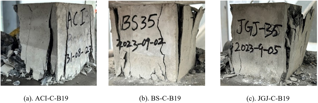
The failure pattern of RC cylinders was examined. The vertical macro cracks were observed in the RC cylinders, which extended from top to bottom with lateral expansion, and the concrete cover was separated from the main core of the concrete. The BFRP strips were ruptured at the bottom sections of some specimens. After the ultimate failure, the internal reinforcement was checked, and it was found that the BFRP transverse reinforcement (spiral/ties) ruptured in the mid-height region. The vertical supporting steel rods were found buckled significantly in the mid-height region where the BFRP stirrup was ruptured. The degree of buckling in the longitudinal steel rods varied based on the spacing of spirals/ties. RC cylinders with close spirals/tie spacing, i.e., 45 mm exhibited less buckling compared to those with larger spacings, i.e., 60 mm and 90 mm (Figure 5a–g). The failure patterns of RC cylinders, reinforced with 6 mm BFRP spirals and 6 mm longitudinal steel bars, included basalt CA crushing, vertical macrocracks, and chipping of concrete. The steel bar buckled as a result of the BFRP spirals breaking at mid-height. Closer BFRP spiral spacing (45 mm) resulted in less buckling, which indicates a greater confinement effect. Concrete failure and steel bar buckling were more severe in the cylinders with a larger spacing of 90 mm (Figure 5h). The RC cylinders strengthened with 6 mm steel ties and 3 mm longitudinal steel rods, exhibited substantial vertical macro cracks and concrete cover spalling. The degree of concrete degradation was more evident in specimens with broader steel tie spacings, i.e., 60 mm and 90 mm. The spacing of the steel ties influenced crack propagation, with increased spacing resulting in more significant cracking. The longitudinal steel rods demonstrated significant buckling, with larger tie spacing (Figure 5i). The internal reinforcement sectional views are illustrated in Figure 6.

Failure modes of RC cylinders.
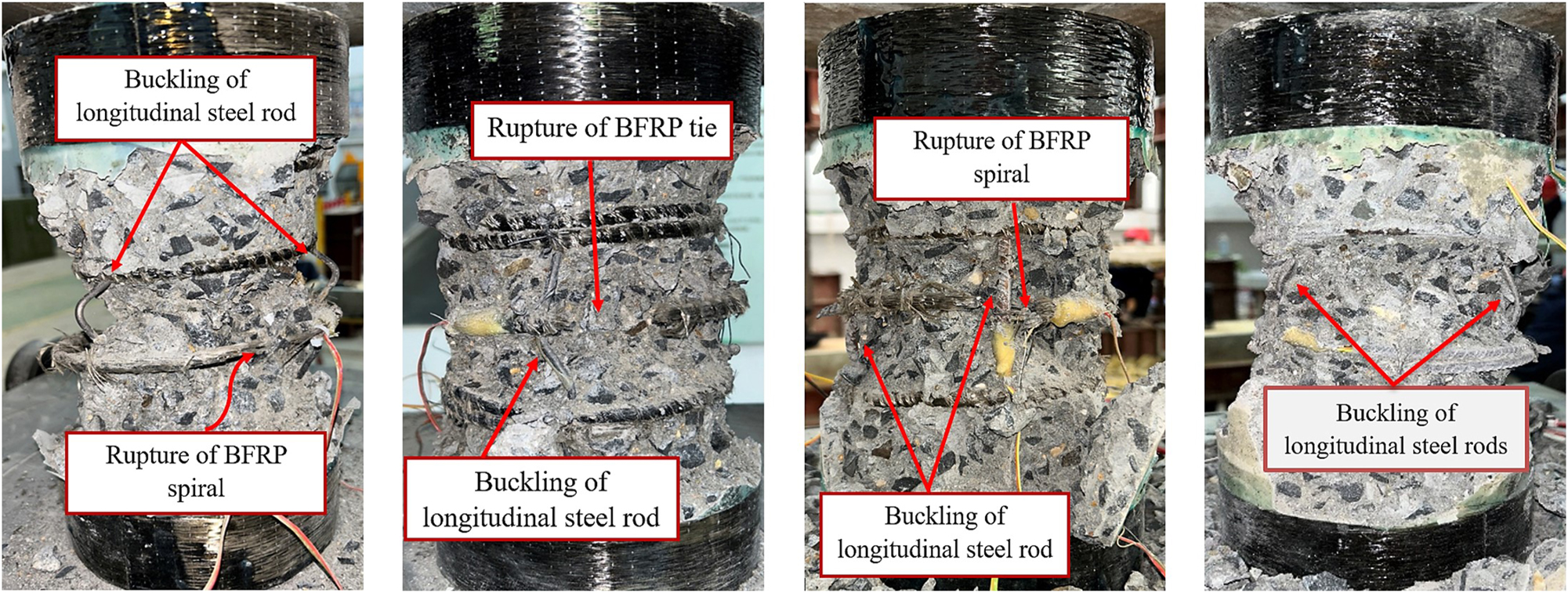
Internal view of the reinforcement sections after ultimate failure.
The RC cylinders failed, generating a loud cracking noise. The concrete cover spalling was marked by separating large pieces of concrete from sides. Once the surface spalled, substantial cracking in the concrete core caused the lateral expansion, starting the passive confining pressure of the BFRP transverse reinforcements. At this moment, the confining restraint provided by the BFRP transverse reinforcement was activated, and the cylinder became able to carry the compressive loading further. As a result, the concrete was crushed, and the BFRP spirals/ties ruptured with the buckling of longitudinal steel bars/steel rods. The observations at the maximum load stage indicate that the BFRP spirals/ties activated to confine the concrete core after concrete spalling started from the specimen’s sides and macro cracks developed. In the end, the cylinders repeatedly exhibited the development of buckling of the steel bars/steel rods, yielding of the BFRP spirals/ties, fracture of BFRP spirals/ties, and crushing of concrete. The major vertical cracks were spread between the ends of the BFRP-RC cylinders.
The tested RC cylinders’ visual examination showed that the transverse reinforcement spacing and arrangement had a substantial impact on the degree and pattern of cracking, concrete spalling, and crushing. Specimens with 90 mm BFRP stirrup spacing had extensive vertical cracks and localized spalling in the mid-height area, signifying inadequate confinement. Conversely, specimens with 45 mm spacing demonstrated a distribution of fine cracks accompanied by controlled spalling, indicating efficient lateral confinement pressure and energy accumulation. The observed failure was qualitatively compatible with the estimated GF and ductility index, despite the fact that exact crack widths and spalled concrete volume were not quantified. In general, specimens that displayed significant spalling and extensive longitudinal cracks demonstrated reduced GF and GAcc. In contrast, dense transversely spaced specimens retained core integrity and showed superior post-peak behavior. The function of BFRP transverse confinement in controlling crack development and postponing brittle failure is further supported by these failure characteristics.
3.3 Compressive strength
3.3.1 Plain concrete
The cube specimens were tested to confirm the designed characteristic CS of concrete. The test results obtained for cubes are given in Table 5. These CS results are the average of three results from three specimens. Compared with the designed trial characteristic strength (ƒ cu) of 43.3 MPa, cube specimens of ACI, BS, and JGJ achieved 4.8 %, 8.8 %, and 2.3 % higher average 28-day CS (ƒ cum) respectively, proving that the concrete mixtures were designed correctly and the CS results were in perfect agreement.
Compressive strength results of PC cubes.
| CMD code | Specimens (mm) | Specimen ID | ƒ cum, 28d (MPa) |
|---|---|---|---|
| ACI | Cube 150 × 150 × 150 |
PC-ACI-C | 45.5 |
| BS | PC-BS-C | 47.5 | |
| JGJ | PC-JGJ-C | 44.3 |
-
PC = plain concrete, ACI/BS/JAJ = CMD codes, C = cube.
3.3.2 Reinforced concrete
This section contains a detailed discussion and comparative analysis of the compression tests performed on the RC cylinders. The CS results of groups RC-1 to RC-5 cylinders are presented in Table 6. The specimen IDs are symbolized as follows: the first letter refers to the CMD code, followed by the B(S)/B(T)/S(T) indicating stirrups types, then followed by the number which refers to the diameter of the stirrups and rib spacing. For instance, ACI-B(S)6–45 indicates the ACI CMD code, reinforced with BFRP spirals of 6 mm at a spacing of 45 mm.
Experimental results of RC cylinders: RC group 1-5.
| Group | Specimen ID | Transverse reinforcement | Longitudinal reinforcement | CS MPa | GAcc kN.mm2 | GF kN.mm | Ductility |
|---|---|---|---|---|---|---|---|
| RC-1 | ACI-B(S)6-45 | BFRP spirals ∅6@ 45 mm |
Steel rods ∅3 mm |
38.8 | 2,356.9 | 1,405.5 | 1.24 |
| ACI-B(S)6-60 | BFRP spirals ∅6@ 60 mm |
34.9 | 1,870.5 | 1,186.5 | 1.31 | ||
| ACI-B(S)6-90 | BFRP spirals ∅6@ 90 mm |
33.9 | 1,962.2 | 1,199.2 | 1.11 | ||
| BS-B(S)6-45 | BFRP spirals ∅6@ 45 mm |
Steel rods ∅3 mm |
39.6 | 2,245.3 | 1,405.5 | 1.19 | |
| BS-B(S)6-60 | BFRP spirals ∅6@ 60 mm |
37.2 | 1,911.9 | 1,187.2 | 1.21 | ||
| BS-B(S)6-90 | BFRP spirals ∅6@ 90 mm |
36.9 | 1,906.1 | 1,133.7 | 1.10 | ||
| JGJ-B(S)6-45 | BFRP spirals ∅6@ 45 mm |
Steel rods ∅3 mm |
34.4 | 2,606.1 | 1,877.1 | 1.29 | |
| JGJ-B(S)6-60 | BFRP spirals ∅6@ 60 mm |
32.7 | 2,078.8 | 1,339.5 | 1.29 | ||
| JGJ-B(S)6-90 | BFRP spirals ∅6@ 90 mm |
31.4 | 2,412.7 | 1,607.9 | 1.26 | ||
| ACI-B(T)6-45 | BFRP ties ∅6@ 45 mm |
Steel rods ∅3 mm |
40.5 | 2,434.5 | 1,504.8 | 1.20 | |
| ACI-B(T)6-60 | BFRP ties ∅6@ 60 mm |
38.6 | 2,623.3 | 1,702.5 | 1.22 | ||
| ACI-B(T)6-90 | BFRP ties ∅6@ 90 mm |
37.3 | 2,295.9 | 1,358.8 | 1.17 | ||
| BS-B(T)6-45 | BFRP ties ∅6@ 45 mm |
Steel rods ∅3 mm |
41.3 | 2,192.5 | 1,132.4 | 1.19 | |
| BS-B(T)6-60 | BFRP ties ∅6@ 60 mm |
40.4 | 2,533.5 | 1,692.2 | 1.16 | ||
| BS-B(T)6-90 | BFRP ties ∅6@ 90 mm |
36.7 | 2,243.4 | 1,298.5 | 1.14 | ||
| JGJ-B(T)6-45 | BFRP ties ∅6@ 45 mm |
Steel rods ∅3 mm | 34.7 | 2,331.2 | 1,415.6 | 1.25 | |
| JGJ-B(T)6-60 | BFRP ties ∅6@ 60 mm |
33.2 | 2,735.5 | 1,962.8 | 1.35 | ||
| JGJ-B(T)6-90 | BFRP ties ∅6@ 90 mm |
31.6 | 1,640.5 | 969.5 | 1.22 | ||
| RC-3 | ACI-B(S)6-45-SB6 | BFRP spirals ∅6@ 45 mm |
Steel bars ∅6 mm |
39.2 | 2,380.8 | 1,458.5 | 1.20 |
| ACI-B(S)6-60-SB6 | BFRP spirals ∅6@ 60 mm |
35.5 | 2,282.4 | 1,497.6 | 1.31 | ||
| ACI-B(S)6-90-SB6 | BFRP spirals ∅6@ 90 mm |
35.5 | 1,662.8 | 728.6 | 1.09 | ||
| RC-4 | ACI-B(S)8-45 | BFRP spirals ∅8@ 45 mm |
Steel rods ∅3 mm |
38.8 | 4,414.8 | 1,392.5 | 1.19 |
| ACI-B(S)8-60 | BFRP spirals ∅8@ 60 mm |
34.3 | 2,221.7 | 1,552.5 | 1.37 | ||
| ACI-B(S)8-90 | BFRP spirals ∅8@ 90 mm |
34.2 | 1,816.5 | 1,120.8 | 1.15 | ||
| RC-5 | ACI-S(T)6-45 | Steel ties ∅6@ 45 mm |
Steel rods ∅3 mm |
42.6 | 3,336.8 | 1,860.3 | 1.30 |
| ACI-S(T)6-60 | Steel ties ∅6@ 60 mm |
38.2 | 3,043.6 | 1,926.3 | 1.36 | ||
| ACI-S(T)6-90 | Steel ties ∅6@ 90 mm |
36.3 | 2,288.5 | 1,268.7 | 1.19 |
In group RC-1 specimens, the ACI-B(S)6–45 attained the highest CS of 38.8 MPa, surpassing ACI-B(S)6–60 (34.9 MPa) and ACI-B(S)6–90 (33.9 MPa) by 10.1 % and 12.6 % respectively. Likewise, BS-B(S)6–45 had the highest CS, 6.1 % and 6.8 % higher than BS-B(S)6–60 and BS-B(S)6–90, respectively. The JGJ-B(S)6–45 exhibited 5 % and 9 % higher CS than the counterparts with 60 and 90 (mm) spacing. In group RC-2 specimens, the ACI-B(T)6–45 achieved the maximum CS, i.e., 4.7 % and 8 % higher than those with 60 and 90 (mm) tie spacings, respectively. Results for BS-B(T)6–45 were 2.2 % and 12.1 % higher than those with 60 and 90 (mm) tie spacing. The CS of JGJ-B(T)6–45 specimen was 5 % and 9 % higher than those with 60 and 90 (mm) spacings, respectively. In group RC-3 specimens prepared with transverse reinforcement of 6 mm BFRP spirals and longitudinal reinforcement of 6 mm steel bars, the ACI-B(S)6-45-SB6 achieved 9.4 % higher CS than the counterparts with 60 and 90 (mm) spiral spacings. In group RC-4, the ACI-B(S)8–45 achieved the highest CS, i.e., 11.6 % higher than ACI-B(S)8–60 and ACI-B(S)8–90, respectively. In group RC-5 specimens, ACI-S(T)6–45 exhibited 10.3 % and 14.8 % higher CS than specimens with 60 and 90 (mm) tie spacings, respectively. From the results, it is cleared that the RC cylinders with closer transverse BFRP/steel stirrup (45 mm) exhibited higher CS than those specimens with larger spacings, i.e., 60 and 90 (mm). This higher CS is due to the higher confining pressure and support to the central concrete core provided by the denser spirals/ties.
In comparison to the RC cylinders with BFRP spirals, the RC cylinders with BFRP ties showed greater CS. The group RC-2 ACI cylinders with BFRP ties having spacings of 45, 60, and 90 (mm) offered 4.2 %, 9.6 %, and 9.1 % higher CS than their counterparts of group RC-1 with BFRP spirals of the same spacings, respectively. Similarly, the BS RC cylinders with BFRP ties of 45 and 60 (mm) spacings had 4.1 % and 8 % greater CS than those with the same BFRP spiral spacings, while those with 90 mm spacings had nearly identical CS. The JGJ RC cylinders utilizing BFRP ties and BFRP spirals demonstrated comparable CS across the specified rib spacings. This comparison shows that the BFRP ties have a margin over the BFRP spirals with various spacings in terms of CS. The CS of group RC-1 ACI cylinders reinforced transversely with 6 mm BFRP spirals and 3 mm steel rods as longitudinal support was compared to the group RC-3 ACI cylinders reinforced longitudinally with 6 mm steel rebars. The RC cylinders of groups RC-3 and RC-1 had almost the same CS at 45 and 60 (mm) rib spacings, however, cylinders of group RC-3 had 4.5 % higher CS at 90 mm spiral spacings. In the case of group RC-1 (6 mm BFRP spirals) and group RC-4 (8 mm BFRP spirals), no substantial fluctuation was seen in the CS, showing that the diameter of the BFRP spiral bar did not influence in terms of CS. At 45 mm rib spacing, the group RC-5 cylinders (6 mm steel ties) had 5 % greater CS than group RC-2 cylinders with BFRP ties, but at 60 and 90 (mm) rib spacings, both had almost the same CS. In terms of CS, specimens with steel and BFRP ties exhibited no significant differences, demonstrating the efficacy of BFRP transverse reinforcement. The BFRP bars can be an outstanding substitute for steel bars as transverse reinforcement in terms of achieving comparable CS with low cost and more resistance to harsh exposures.
3.3.3 Comparison to contemporary work
To assess the reliability and technical validity of the current study, the strength results were compared with relevant studies that investigated the axial compressive behavior of concrete columns reinforced with BFRP stirrups. The studies were chosen for comparison due to their utilization of comparable transverse reinforcement configurations, materials, and stirrup spacings.
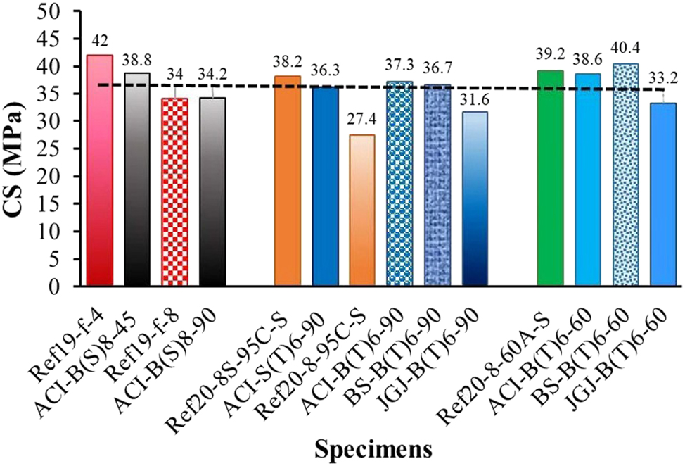
A study [19] investigated concrete columns reinforced with BFRP bars and transversely confined using BFRP spirals of varying diameters and spacings. Specimens f-4 and f-8 were chosen in a nearly matched arrangement, using concrete of comparable strength and longitudinal epoxy resin rods with 8 mm BFRP spirals spaced at 46 and 92 (mm), respectively. The specimens f-4 and f-8 obtained CS of 42 MPa and 34 MPa, demonstrating the reduction of strength with the increased BFRP spiral spacing. In the current study, the specimens ACI-B(S)8–45 and ACI-B(S)8–90 of group RC-4 achieved 38.8 MPa and 34.2 MPa CS. These specimens were reinforced with 8 mm BFRP spirals at 45 and 90 (mm) spacings, respectively. The observed strength trends are notably consistent, as both studies validate that closer BFRP spiral spacing considerably improves strength. The observed strength reduction in the current ACI-B(S)8–45 specimen can be linked to variations in the type of longitudinal rods and the CMD code utilized.
In another investigation [20], square columns measuring 250 × 250 (mm) and 800 mm in height were reinforced with steel longitudinally, and with BFRP/steel ties of 8 and 12 (mm) diameter spaced at 60, 95, and 140 (mm) intervals. A CS of 38.2 MPa was attained by the reference specimen 8S–95C–S reinforced with 8 mm steel ties spaced 95 mm apart. However, despite the lower tie diameter, the group RC-5 specimen ACI-S(T)6–90 reinforced with 6 mm steel ties at 90 mm spacing achieved 36.3 MPa in the current investigation. The similar strength indicates that the diameter difference was compensated by more consistent confinement provided by the circular section geometry in this study as opposed to the square section used in the reference study.
In a specific case, reference specimens 8-95C–S, which were reinforced using steel longitudinal bars and 8 mm BFRP ties at 95 mm spacing, achieved 27.4 MPa. Conversely, the specimens of RC-2 group of current study (ACI-B(T)6–90, BS-B(T)6–90, and JGJ-B(T)6–90), using 6 mm BFRP ties at 90 mm spacing, attained 37.3 MPa, 36.7 MPa, and 31.6 MPa, respectively. This research demonstrates that the notably superior CS (13 %–26 %) underscore the benefits of circular cross-sections and potentially more efficient tie details, especially with smaller diameter BFRP ties. The findings emphasize the possible limitations of square-section columns when reinforced with different BFRP ties, as stress concentrations at the corners lead to less effective confinement. The reference specimen 8-60 A-S achieved 39.2 MPa by using 8 mm BFRP ties spaced at 60 mm. The corresponding specimens (ACI-B(T)6–60, BS-B(T)6–60, and JGJ-B(T)6–60) in the current study achieved 38.6 MPa, 40.4 MPa, and 33.2 MPa, respectively. These findings further illustrate that CMD code has a meaningful influence on confined strength, with BS code performing better in this configuration. Additionally, it supports the usefulness of closely spaced BFRP connections, even at lower diameters. The graphical presentation is illustrated in Figure 7.
Comparison to contemprary studies.
3.4 Load-displacement behavior
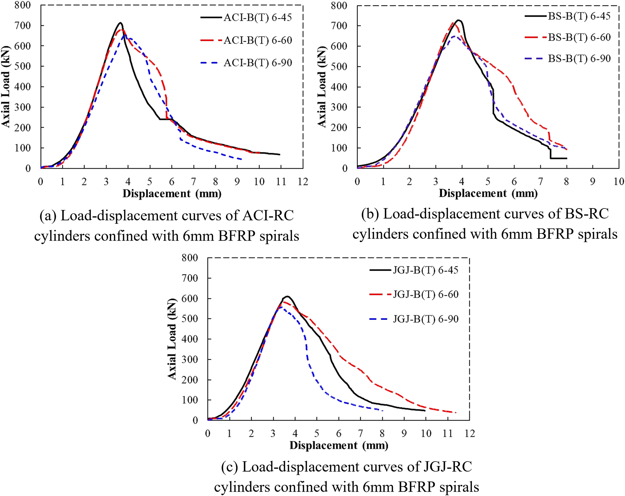
The compression behaviors of RC cylinders are graphically illustrated in terms of load-displacement curves. Figure 8 represents the overall compression behaviors of group RC-1 (ACI, BS, and JGJ) specimens. The load-displacement curves begin with a linear pattern, which illustrates the concrete’s and the BFRP reinforcement’s elastic nature. This linearity indicates that the concrete and reinforcement are functioning together without considerable cracking. In Figure 8A, the ACI RC cylinders showed linear behavior in ascending regions until their respective Pmax but displayed variation in post-peak behavior. The BS-B(S)6–45 and BS-B(S)6–60 curves exhibited linear behavior in the elastic region up to their Pmax, as shown in Figure 8B, whereas the BS-B(S)6–90 curve displayed greater plasticity and increased gradually. The stiffness is reduced as microcracks develop into macrocracks in the non-linear section of BS-B(S)6–90. In Figure 8J, the curves JGJ-B(S)6–60 and JGJ-B(S)6–90 start to deviate from their initial linearity as the load approaches the peak as compared to the JGJ-B(S)6–45 curve. It indicates the development of micro-cracks in the elastic region. After the Pmax, the curves showed ductile behavior and failed gradually. Figure 9 presents the compressive behaviors of group RC-2 specimens. In Figure 9A, curves ACI-B(T)6–45 and ACI-B(T)6–60 showed identical pre-peak behaviors up to the Pmax, with a noticeable variation in the post-peak region. The curve ACI-B(T)6–90 showed deviation in the transition and post-peak regions. The curves BS-B(T)6–45 and BS-B(T)6–90 ascended identically to the maximum load point but showed noticeable variation in the post-peak region while BS-B(T)6–60 showed deviation in the elastic region (Figure 9B). In Figure 9J, all the curves of JGJ-RC cylinders followed almost the same ascending pattern till their respective Pmax but displayed a noticeable variation in post-peak region. In Figure 10, the load-displacement curves of group RC-3 specimens are displayed. In the elastic region, all the curves upsurged identically while the curve ACI-B(S)6-90-SB6 showed a slight variation in the transition zone and a noticeable drop in the post-peak region. This decline indicates the cracks enlargement, resulting in less load-bearing capability. The ACI-B(S)6-45-SB6 and ACI-B(S)6-60-SB6 showed more resistance against the loading. In Figure 11, the specimens of group RC-4 displayed the same compressive behavior and mounted identically in the elastic and transition regions but showed different post-peak behaviors. At the Pmax stage, internal damage in the concrete reached a critical level, though the BFRP confinement delayed full collapse by containing the lateral expansion (ACI-B(S)8–45). Figure 12 displays the load-displacement curves of group RC-5 specimens. All the curves ascended almost in the same manner with slight deviation but showed different post-peak behaviors.
Group RC-1: Load-displacement behavior of RC cylinders confined with 6 mm BFRP spirals at various spacings.

Group RC-2: Load-displacement behavior of RC cylinders confined with 6 mm BFRP ties at various spacings.
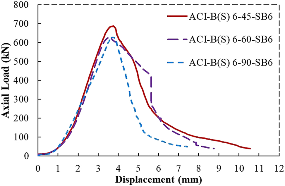
Group RC-3: Load-displacement behavior of ACI-RC cylinders confined with 6 mm BFRP spirals & 6 mm steel bars.
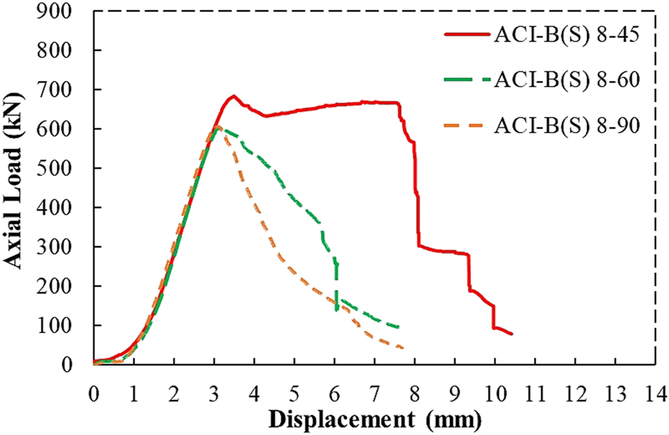
Group RC-4: Load-displacement behavior of ACI-RC cylinders confined with 8 mm BFRP spirals at various spacings.
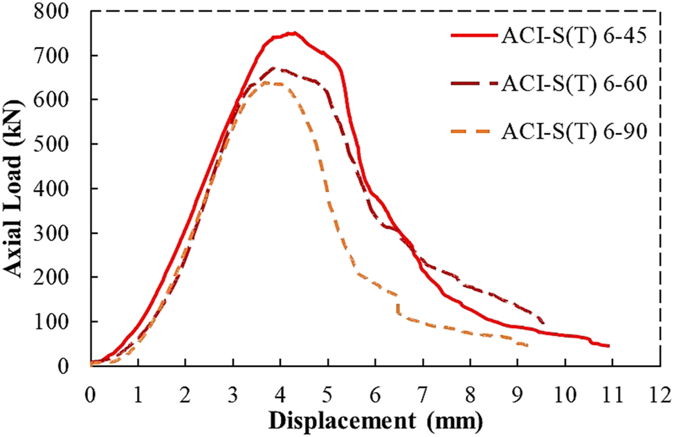
Group RC-5: Load-displacement behavior of ACI-RC cylinders confined with 6 mm steel ties at various spacings.
The post-peak behaviors of RC cylinders demonstrate that BFRP reinforcements continue to support some load despite extensive concrete damage. This behavior shows that the RC cylinders retained some residual capacity due to the transverse confining effect of BFRP. The analysis of failure modes and the assessment of load-displacement behavior indicate that differences predominantly occur in the post-peak region, attributable to variations in the rib spacings of BFRP spirals/ties, the diameter of BFRP spirals, the type of transverse reinforcement, and the substitution of longitudinal steel rods with steel rebars. The CMD codes exhibited minimal influence on the failure modes of the RC cylinders due to the dominant behavior of reinforcements.
3.5 Energy accumulation
The total energy accumulation during the testing, from the first loading point to the ultimate failure point, is termed the accumulated energy (GAcc). Table 6 presents the results of the GAcc of RC cylinders (groups RC 1–5). In the group RC-1, ACI-B(S)6–45 achieved 20.6 % and 16.7 % higher GAcc than those with larger spacings, i.e., 60 and 90 (mm), respectively. In the case of BS RC cylinders, BS-B(S)6–45 gained about 15 % higher GAcc than BS-B(S)6–60 and BS-B(S)6–90, respectively. The JGJ RC cylinders (JGJ-B(S)6–45) exhibited 20.2 % and 7.4 % higher GAcc than the JGJ-B(S)6–60 and JGJ-B(S)6–90. In this case, the RC cylinders with condensed BFRP spiral spacings (45 mm) exhibited higher GAcc than those with larger BFRP rib spacings. The reason could be the higher confining pressure provided to the concrete core by the concentrated BFRP spirals, resulting in higher CS and GAcc. In the case of group RC-2 specimens, the ACI-B(T)6–60 offered 7.2 % and 12.5 % higher GAcc than ACI-B(T)6–45 and ACI-B(T)6–90. Similarly, the BS-B(T)6–60 offered 13.5 % and 11.5 % higher GAcc than BS-B(T)6–45 and BS-B(T)6–90, respectively. The same trend was found in the JGJ RC specimens, i.e., JGJ-B(T)6–60 achieved 14.8 % and 40 % higher GAcc than JGJ-B(T)6–45 and JGJ-B(T)6–90, respectively. The group RC-2 specimens of moderate BFRP tie spacings (60 mm) offered the highest GAcc than those having tie spacings of 45 and 90 (mm). The group RC-3 specimens ACI-B(S)6-45-SB6 achieved 4.1 % and 30.2 % higher GAcc than those with larger spiral spacings, i.e., ACI-B(S)6-60-SB6, and ACI-B(S)6-90-SB6, respectively. In the case of group RC-4, the specimens ACI-B(S)8–45 achieved 49.7 % and 58.9 % higher GAcc than the ACI-B(S)8–60 and ACI-B(S)8–90, respectively. In the case of group RC-5, the specimen ACI-S(T)6–45 exhibited 8.8 %, and 31.4 % higher GAcc than those with the larger ties spacings, i.e., ACI-S(T)6–60 and ACI-S(T)6–90, respectively. In groups RC-3, RC-4, and RC-5, the close rib spacings (45 mm) was more effective in terms of GAcc. The GAcc graphical presentation of groups RC 1–5 is illustrated in Figures 13, 14, and 15.
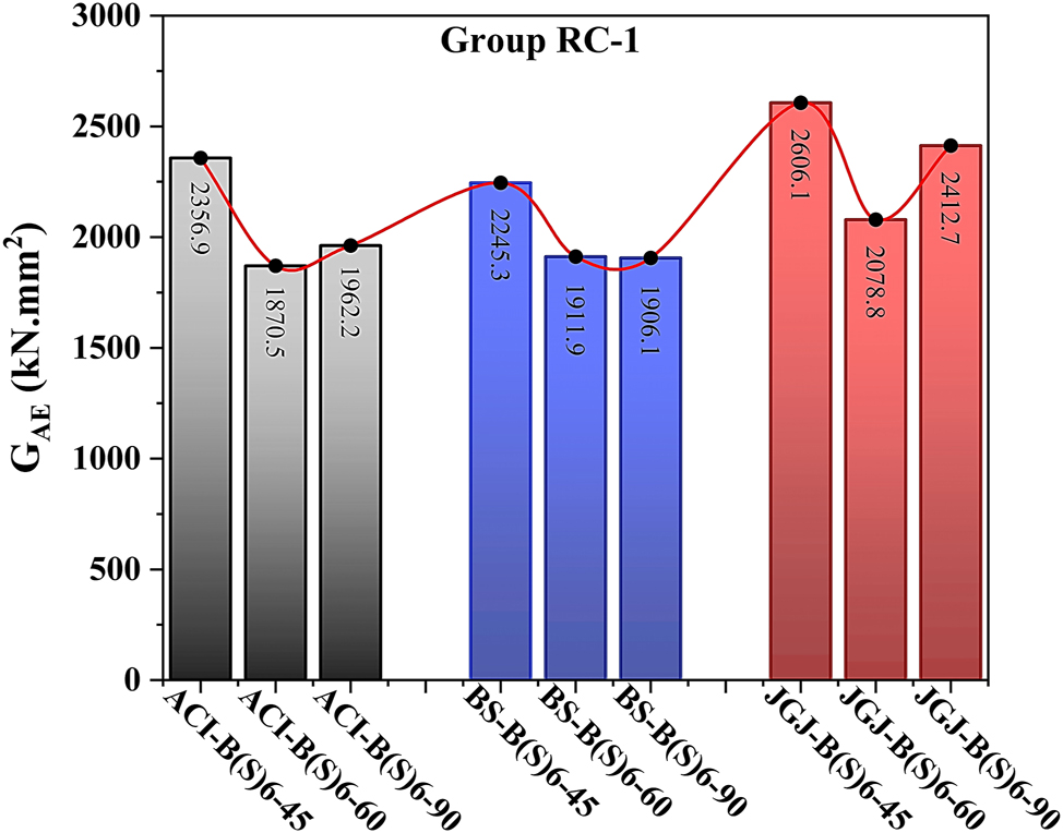
Accumulated energy of RC cylinders: BFRP spirals of 6 mm at various spacings (group RC-1).
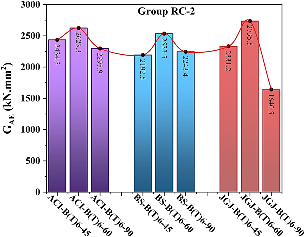
Accumulated energy of RC cylinders: BFRP ties of 6 mm at various spacings (group RC-2).
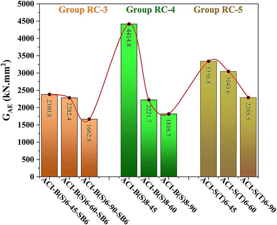
Accumulated energy results of RC cylinders: Group RC-3, group RC-4 and group RC-5.
The comparison of GAcc between group RC-1 and group RC-2 was made. In this case, ACI-B(S)6–45 specimens achieved 11.5 % higher GAcc than ACI-B(T)6–45 while ACI-B(T)6–60 and ACI-B(T)6–90 offered 28.7 % and 14.5 % higher GAcc than ACI-B(S)6–60 and ACI-B(S)6–90. It was found that RC specimens reinforced with BFRP spiral having small spacings of 45 mm are more effective than the RC specimens reinforced with BFRP ties having same spacings. In contrast, in the case of larger spacings, i.e., 60 and 90 (mm), the RC specimens with BFRP ties performed well and resisted longer against the applied load, hence gaining a higher GAcc. The BS-B(S)6–45 and BS-B(T)6–45 having 45 mm BFRP spirals and ties spacing offered almost the same GAcc with a 2.4 % variation while BS-B(T)6–60 and BS-B(T)6–90 exhibited 24.5 % and 10.2 % higher GAcc than specimens having BFRP spirals, i.e., BS-B(S)6–60 and BS-B(S)6–90, respectively. The results of the GAcc of JGJ RC specimens showed that JGJ-B(S)6–45 and JGJ-B(S)6–90 achieved 10.5 % and 32 % higher GAcc than JGJ-B(T)6–45 and JGJ-B(T)6–90, respectively. However, in the case of 60 mm spacings, the JGJ-B(T)6–60 gained 24 % higher GAcc than JGJ-B(S)6–60. In comparison of group RC-1 and group RC-3, the ACI-B(S)6–45 and ACI-B(S)6-45-SB6 offered almost the same GAcc. In the case of 60 mm spiral spacings, ACI-B(S)6-60-SB6 gained 18 % higher GAcc than ACI-B(S)6–60 while in the case of 90 mm spiral spacings, ACI-B(S)6–90 achieved 15.2 % higher GAcc than ACI-B(S)6-90-SB6. The GAcc of group RC-1 and group RC-4, the ACI-B(S)8–45 and ACI-B(S)8–60 achieved 42.8 % and 15.8 % higher GAcc than ACI-B(S)6–45 and ACI-B(S)6–60. However, in the case of 90 mm spacings, the ACI-B(S)6–90 offered 7.5 % higher GAcc than ACI-B(S)8–90. The GAcc of group RC-2 and group RC-5 was compared and it was found that ACI-S(T)6–45, ACI-S(T)6–60 exhibited 27 % and 13.8 % higher GAcc than ACI-B(T)6–45, ACI-B(T)6–60, while ACI-S(T)6–90 and ACI-B(T)6–90, offered nearly the same GAcc, respectively.
The GAcc results indicate a significant influence of reinforcing type, rebar diameter, stirrup spacing, and CMD codes on the energy absorption capabilities of RC cylinders. RC groups using larger BFRP bar size (group RC-4) or steel ties (group RC-5) continuously showed greater GAcc. In BFRP-reinforced configurations, BFRP ties (group RC-2) showed superior performance compared to BFRP spirals (group RC-1) at larger spacings, suggesting that BFRP ties are more efficient for specimens requiring enhanced crack control at larger stirrup spacing. The results indicate that designs with steel ties and larger diameter BFRP bars with closer stirrup spacing are most effective for applications requiring significant energy absorption under compressive loads. Conversely, BFRP ties may provide a feasible alternative for comparable advantages, particularly in configurations with low confinement demands. This knowledge can direct the choice of reinforcement configurations and types to maximize the durability and compressive resilience of RC structures in a range of structural applications.
3.6 Post-peak fracture energy
The fracture energy (GF) quantifies the energy dissipation during the fracture growth in concrete components and the failure procedure after the Pmax. The GF was calculated from the point Pmax to the ultimate failure point under the load-displacement curve. It’s an essential metric for comprehending concrete’s post-peak behavior, especially in loaded structural components. This crucial fracture mechanics parameter should be explored comprehensively and employed in the structural design process to guarantee that structures can resist anticipated loading conditions without failing catastrophically. This section analyzes the post-peak behavior results of RC cylinders with various reinforcement arrangements in terms of GF. The GF results of groups RC-1 - RC-5 are given in Table 6.
The group RC-1 specimens experienced improved confinement and resistance to crack propagation following the Pmax due to the increased GF with closer BFRP spiral spacing. In this case, ACI-B(S)6–45 offered 15.5 % and 14.7 % higher GF than ACI-B(S)6–60 and ACI-B(S)6–90, respectively. The specimens BS-B(S)6–45 gained 15.8 % and 19.3 % higher GF than BS-B(S)6–60 and BS-B(S)6–90, respectively. Similarly, the specimens JGJ-B(S)6–45 exhibited 28.6 % and 14.3 % higher GF than JGJ-B(S)6–60 and JGJ-B(S)6–90, respectively. The GF results of group RC-2 demonstrated that BFRP ties offer increased GF at intermediate tie spacing (60 mm) in contrast to the closer tie spacing of 45 mm, which achieved lower GF and GAcc due to the unexpected post-peak failure despite achieving the highest CS. The RC cylinders with 45 mm BFRP tie spacing demonstrated decreased GF compared to the 60 mm arrangement, contrary to usual confinement patterns. In this case, the dense ties reduced post-peak toughness by causing localized stiffness zones that either caused premature microcracking or stress concentrations that limited the development of distributed microcracks. It was found that the ACI-B(T)6–60 achieved 11.6 % and 20.2 % higher GF than ACI-B(T)6–45 and ACI-B(T)6–90, respectively. The same trend was found in BS RC specimens, i.e., BS-B(T)6–60 offered 33 % and 22.3 % higher GF than BS-B(T)6–45 and BS-B(T)6–90, respectively. The specimens JGJ-B(T)6–60 exhibited 27.9 % and 50.6 % higher GF than JGJ-B(T)6–45 and JGJ-B(T)6–90, respectively.
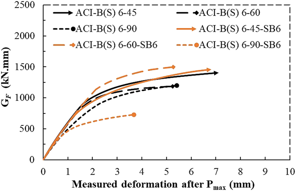
In the group RC-3 specimens, maximum GF was attained with moderate (60 mm) and close (45 mm) BFRP spiral spacings while GF decreased significantly at larger spacings (90 mm). Based on the results, it appeared that closer BFRP confinement is needed to maintain optimal fracture resistance, as the BFRP spiral efficacy decreases with wider distances. In this case, the specimens ACI-B(S)6-45-SB6 and ACI-B(S)6-60-SB6 achieved almost the same GF but ACI-B(S)6-90-SB6 showed about 50 % decline in the post-peak GF. The GF results of group RC-4 demonstrated that larger diameter BFRP bars enhance stiffness; however, the findings imply that wider BFRP spiral spacing can decline the GF, indicating the necessity for a balance between BFRP bar size and spacing to achieve effective confinement. In this configuration, the ACI-B(S)8–60 showed the highest GF, i.e., 10.3 % and 27.8 % higher than ACI-B(S)8–45 and ACI-B(S)8–90, respectively. In the group RC-5, the use of steel ties offered superior confinement, enhancing GF by effectively limiting lateral expansion, hence enabling the concrete to withstand greater fracture stresses. In this case, the ACI-S(T)6–45 and ACI-S(T)6–60 offered nearly the same GF with a variation of 3.4 % but ACI-S(T)6–90 showed 34.1 % decreased GF than ACI-S(T)6–60. The graphical results of GF of group RC-1 to group RC-5 are illustrated in Figures 16, 17, 18, 19, 20, and 21.
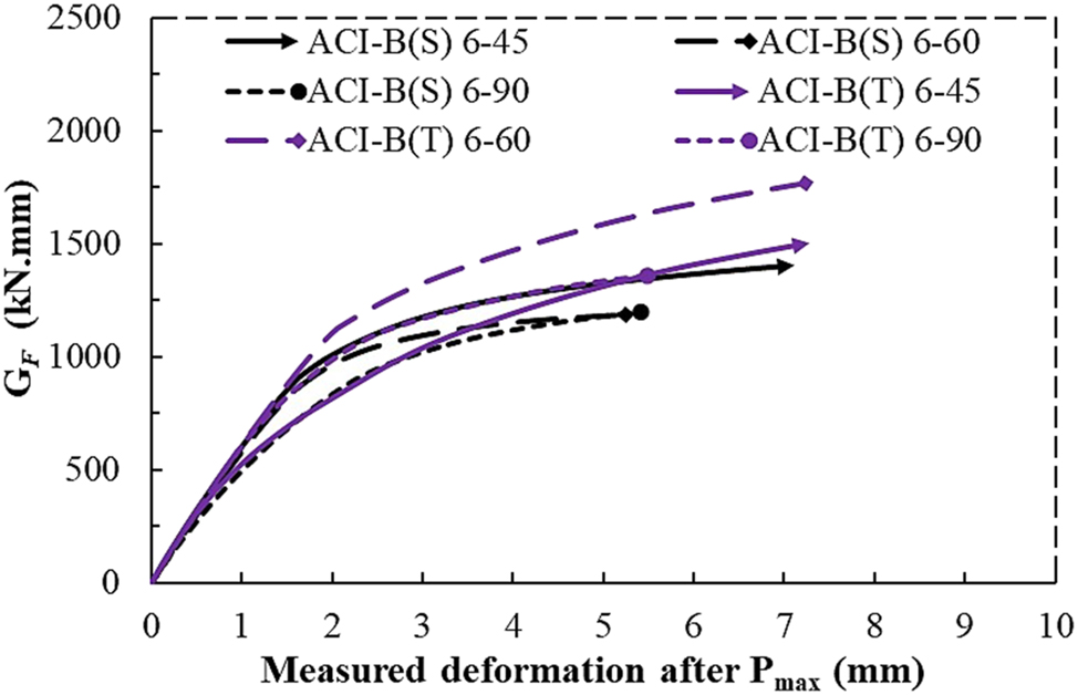
GF results of ACI-RC: 6 mm BFRP spirals/ties.

GF results of BS-RC: 6 mm BFRP spirals/ties.

GF results of JGJ-RC: 6 mm BFRP spirals/ties.
GF results of ACI-RC: 6 mm BFRP spirals with steel longitudinal rods/bars.

GF results of ACI-RC: 6 & 8 mm BFRP spirals.

GF results of ACI-RC: 6 mm BFRP/steel ties.
The results of GF of group RC-1 with 6 mm BFRP spirals and group RC-2 with 6 mm BFRP ties were compared. The results indicated that specimens of RC-2 generally yielded higher GF than specimens of RC-1, particularly the specimens with the 60 mm ties spacing. The ACI-B(T)6–45, ACI-B(T)6–60, and ACI-B(T)6–90 achieved 6.6 %, 30.3 %, and 11.7 % higher GF than ACI-B(S)6–45, ACI-B(S)6–60, and ACI-B(S)6–90, respectively. In the case of BS RC specimens, the BS-B(S)6–45 exhibited 19.4 % higher GF than BS-B(T)6–45 wihile BS-B(T)6–60 and BS-B(T)6–90 offered 30.1 %, 12.7 % higher post-peak GF than BS-B(S)6–60 and BS-B(S)6–90, respectively. In the case of JGJ RC specimens, the JGJ-B(S)6–45 and JGJ-B(S)6–90 dissipated 24.6 %, 39.7 % higher GF than JGJ-B(T)6–45 and JGJ-B(T)6–90 respectively while the specimens JGJ-B(T)6–60 acieved 31.8 % higher GF than JGJ-B(S)6–60. The specimens of group RC-3 achieved higher GF in closer and intermediate BFRP spiral spacings (45 mm & 60 mm) but dropped sharply at wider spacing (90 mm). The GF results showed that ACI-B(S)6-45-SB6 and ACI-B(S)6-60-SB6 exhibited 3.7 % and 20.8 % higher GF than ACI-B(S)6–45, ACI-B(S)6–60, respectively but in the case of larger spiral spacing, i.e., ACI-B(S)6–90 offered 39.2 % higher GF than ACI-B(S)6-90-SB6. The larger bar diameter in RC-3 enhanced GF under more confined conditions, but it became less effective at wider spacings where the loss of confinement allowed more crack propagation. The GF results of groups RC-1 and RC-4 showed that ACI-B(S)6–45 and ACI-B(S)8–45 achieved nearly the same GF. The ACI-B(S)8–60 offered 23.6 % higher GF than ACI-B(S)6–60 while ACI-B(S)6–90 offered 6.5 % higher GF than ACI-B(S)8–90. The group RC-4 specimens with 8 mm BFRP bars, demonstrated relatively consistent GF but did not outperform RC-1 specimens by a large margin except in intermediate configurations. The larger BFRP bar diameter in RC-4 added stiffness, but without closer confinement, it did not significantly increase GF beyond RC-1’s performance, except at optimal spacings. Group RC-5 specimens generally achieved higher GF than group RC-2, especially in the case of 45 and 60 (mm) tie spacing configurations. The GF results showed that ACI-S(T)6–45 and ACI-S(T)6–60 achieved 19.1 % and 11.6 % higher GF than ACI-B(T)6–45 and ACI-B(T)6–60, but in the case of 90 mm tie spacings, the specimens ACI-B(T)-6-90 offered 6.6 % higher GF than ACI-S(T)6–90. Steel ties in RC-5 outperformed BFRP ties in RC-2 in the case of close and medium tie spacings, by providing more rigid confinement, preventing lateral expansion and enhancing energy absorption during post-peak fractures.
The GF results underscore the critical influence of reinforcement type, BFRP bar diameter, and configuration of transverse reinforcements on the fracture resistance of RC cylinders. Among the evaluated programs, group RC-2 and RC-5 stand out for their superior GF results. Group RC-4 also demonstrated enhanced GF, especially in configurations with intermediate stirrup spacing, where the balance of bar stiffness and confinement was optimal. The utilization of BFRP stirrups can be a good substitute of steel stirrups in the RC columns, as the specimens transversally reinforced with BFRP bars exhibited comparable compressive performance across the different CMD codes. In essence, for applications requiring high GF and resistance to cracking under compressive loading, configurations with steel ties (RC-5) or larger diameter BFRP bars with optimal spacing (RC-2 and RC-4) are recommended and should be explored further on large scale. These setups not only improve fracture resistance but also contribute to the durability and resilience of concrete structures, particularly in demanding structural environments where cracking and failure resistance are paramount.
3.7 Ductility characteristics
From the load-displacement curves, the ductility index of RC cylinders was calculated using the formula
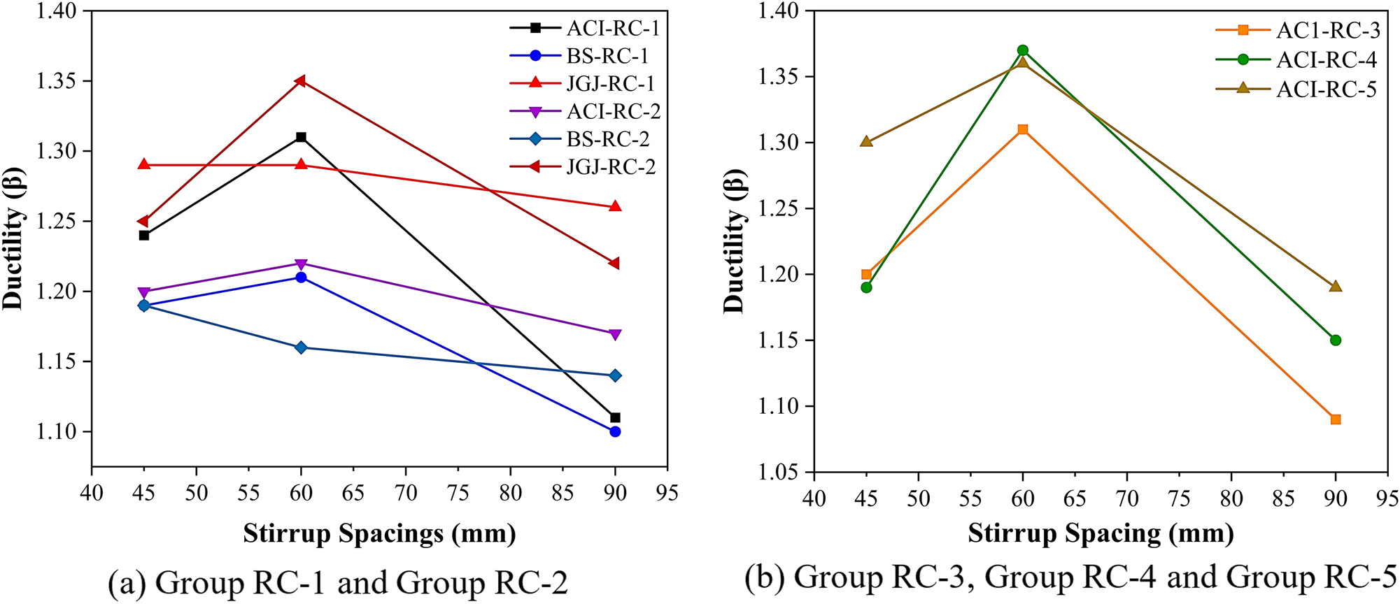
Ductility index of RC cylinders (group RC-1 – group RC-5).
4 Finite element modeling
To complement the experimental program and further interpret the observed behaviors, a numerical investigation was conducted using the finite element method (FEM) in ABAQUS/Standard. The RC cylinders of group RC-1 and group RC-3 that used ACI CMD were selected for the FE study. This modeling aimed to simulate the axial compression behavior of circular RC columns confined with BFRP spirals, and to validate the experimental results. The FEM framework replicated the key parameters of the tested specimens, including geometric configurations, reinforcement details, material properties, and loading conditions.
4.1 Model geometry and configuration
The finite element models were developed to match the tested specimen dimensions and reinforcement configurations described in Section 2. Each RC column model had a diameter of 150 mm and a height of 300 mm. The transverse reinforcement was modeled as continuous BFRP spirals, in accordance with the experimental arrangements. Longitudinal reinforcement was modeled as steel rods (∅3 mm) or steel bars (∅6 mm) depending on the group type. The model incorporated an explicit representation of the concrete core, longitudinal reinforcement, transverse reinforcement, and the thin BFRP sheet wraps at the exterior top and bottom 50 mm sections of the columns. To ensure correct interaction between components, the longitudinal and transverse reinforcements were embedded within the concrete elements. The 3D models for the cylindrical specimens and internal reinforcements arrangement of groups RC-1 and RC-3 are illustrated in Figure 23 (a & b).
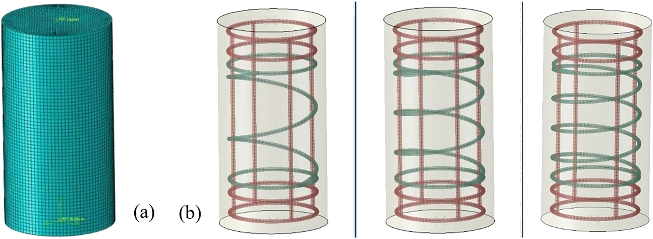
Details of the FE model: (a) concrete solid part and (b) reinforcement truss elements.
4.2 Material models
Concrete behavior was simulated using the Concrete Damaged Plasticity (CDP) model in ABAQUS, which accounts for nonlinear compressive and tensile behavior, stiffness degradation due to damage, and different failure mechanisms under varying stress states. The key CDP parameters, derived from experimental cube compression tests (Table 5) and literature values for similar concrete grades, were as follows: dilation angle (ψ) of 30°, eccentricity (ε) of 0.1, fb0/fc0 ratio of 1.16, K (ratio of second stress invariant) of 0.667, and a viscosity parameter of 0.0001 [58], 59]. The compressive stress–strain curve was defined from the experimental results of ACI CMD, with post-peak softening calibrated to match the observed ductility and GF values.
Longitudinal steel bars were modeled as elastic–plastic materials with isotropic hardening, using experimentally measured yield strengths (Table 2) and an elastic modulus of 200 GPa. Poisson’s ratio was set to 0.3. BFRP spirals and sheets were modeled as linearly elastic up to rupture, consistent with their brittle tensile failure observed experimentally. Elastic modulus and tensile strength were taken from Table 2. The rupture strain was computed as tensile strength divided by elastic modulus. No compression stiffness contribution was included for BFRP bars in the CDP model.
4.3 Meshing strategy
The concrete domain was discretized using C3D8R (8-node linear brick, reduced integration) solid elements to improve computational efficiency while maintaining accuracy. Reinforcement bars were modeled with T3D2 (2-node linear truss) elements. Mesh sensitivity analysis indicated that an element size of approximately 15 mm for the concrete and 10 mm for the reinforcement provided stable results without excessive computational demand.
4.4 Interaction and bonding assumptions
A perfect bond between reinforcement and surrounding concrete was assumed using the embedded region constraint in ABAQUS. The BFRP sheet wraps were modeled as surface layers tied to the concrete in the wrapped regions, assuming full composite action with the underlying core [60], 61].
4.5 Boundary conditions and loading setup
The base of each model was fixed in all translational and rotational degrees of freedom to replicate the rigid platen in the test setup. The load was applied to the top face of the specimen as a displacement-controlled vertical movement, matching the experimental displacement control method. To ensure uniform load transfer, a rigid analytical surface was coupled to the top face of the concrete model.
4.6 Model validation
The FEM models were validated against the experimental results by comparing the predicted CS values and the observed damage modes. Table 7 presents the comparison between experimental and FEM-predicted CS values. Across all specimens, the difference between the simulated and experimental CS values was within 7 %, demonstrating strong agreement and confirming that the modeling approach accurately captured the axial capacity of BFRP-confined RC columns. The highest deviation occurred for the specimen ACI-B(S)6–45 with a difference of 6.87 %, while the smallest deviation (2.23 %) was observed for ACI-B(S)6-45-SB6.
Experimental and FEM model CS results.
| Group | Specimens ID | Experimental CS (P)
(kN) |
CS FEM (P
n
)
(kN) |
(P
n
-P)/P
(%) |
|---|---|---|---|---|
| RC-1 | ACI-B(S)6-45 | 685.3 | 638.2 | 6.87 |
| ACI-B(S)6-60 | 616.1 | 636.9 | 3.38 | |
| ACI-B(S)6-90 | 598.8 | 624.2 | 4.24 | |
| RC-3 | ACI-B(S)6-45-SB6 | 691.9 | 676.5 | 2.23 |
| ACI-B(S)6-60-SB6 | 627.4 | 666.5 | 6.23 | |
| ACI-B(S)6-90-SB6 | 627 | 654.9 | 4.45 |
In terms of damage patterns, the FEM simulations reproduced the key failure characteristics observed experimentally. In both RC-1 and RC-3 models, vertical cracking initiated near the mid-height region, followed by progressive widening of cracks and localized concrete crushing. The simulations also captured the spalling of the concrete cover and the concentration of damage in the central region of the column, corresponding to the experimentally observed rupture locations of BFRP spirals and the buckling zones of longitudinal steel bars. For specimens with closer spiral spacing (45 mm), the numerical damage contours indicated a more uniform distribution of cracking and delayed crushing, while specimens with larger spacing (90 mm) exhibited concentrated damage zones, consistent with reduced confinement efficiency seen in the tests (Figure 24).
The close agreement in CS values and the accurate replication of the failure modes confirm the reliability of the developed FEM framework in predicting the compressive behavior and damage progression of BFRP-confined RC columns. This validated model provides a sound basis for conducting further parametric studies and design optimizations (Figure 24).

Failure modes of FE model of: (a) group RC-1 cylinders and (b) group RC-3 cylinders.
5 Conclusions
The axial compressive behaviors of RC circular cylinders prepared using ACI, BS, and JGJ CMD codes were experimentally and analytically examined. The cylinders were reinforced longitudinally with steel rods/steel bars, transversely with BFRP spirals/ties of 6 and 8 (mm) diameters at various spacings. The study investigated the effects of transverse reinforcement spacing, configuration, and CMD variation on failure modes, confinement efficiency, CS, energy accumulation, and ductility. Based on the findings of this study, the following conclusions are made.
Micro-cracks initiated in ITZ as the compressive loading approached Pmax. Following Pmax, the transfer of load caused a substantial rise in axial stress on the longitudinal reinforcement, resulting in the rupture of the BFRP stirrups, buckling of the longitudinal reinforcement, and concrete cover spalling. The RC cylinders with larger stirrup spacings displyed brittle and severe failure, due to inadequate transverse confinement to prevent the lateral dilation of the concrete core.
The arrangement of transverse reinforcement spacings significantly affected the CS of the RC specimens. The specimens of groups RC-1, RC-2, RC-3, RC-4, and RC-5 having condensed BFRP/steel stirrup spacing (45 mm), offered 6.8 %–12.6 %, 8 %–11 %, 9.4 %, 11.8 %, and 14.8 % higher CS than the specimens with larger spacing (60 mm and 90 mm) across the various CMD codes. The strength improvement is attributed to the enhanced confining pressure of concentrated transverse stirrups, which successfully stabilizes the central concrete core under axial stress.
The stirrup type and spacing play a crucial role in determining the ductility of RC cylinders. After the Pmax, the specimens of groups RC-1 to RC-5 with medium stirrup (BFRP/steel) spacings (60 mm) showed superior ductility performance compared to the specimens with concentrated and larger stirrup spacings (45 mm and 90 mm). The enhanced ductility of specimens having medium stirrup spacing of groups RC-1, RC-2, RC-3, RC-4, and RC-5 measured 2.3 %–15.3 %, 4 %–9.6 %, 16.8 %, 16 %, and 12.5 % respectively. This emphasizes the balance between adequate confinement and controlled deformation capacity at intermediate spacing.
The larger diameter of transverse reinforcement (BFRP spirals), type (steel ties), and spacings significantly influence the energy accumulation (GAcc) of RC specimens. The specimens of group RC-4 (8 mm BFRP spiral) exhibited 46 % higher GAcc compared to the groups RC-1 and RC-3 specimens (6 mm BFRP spiral), while group RC-5 (6 mm steel tie) achieved 27 % higher GAcc than RC-2 specimens (6 mm BFRP tie) with the condensed stirrups (45 mm). Furthermore, the RC specimens across all groups with condensed stirrups exhibited superior GAcc compared to those with wider stirrup spacings; nevertheless, in the case of group RC-2 (BFRP tie), the specimens with medium stirrup spacings offered the highest GAcc.
The closer and medium BFRP stirrup spacings (45 mm and 60 mm) enhance the fracture energy of RC specimens during failure, resulting in improved post-peak load-deformation behavior. The specimens of JGJ CMD in groups RC-1 and RC-2 exhibited slightly higher GF than group RC-5 specimens with steel ties. The JGJ RC specimens in groups RC-1 and RC-2, with 45 mm and 60 mm spacings, demonstrated superior GF performance compared to the specimens of the ACI and BS codes. This underscores the effectiveness of BFRP transverse reinforcement, the characteristics of the material, and the detailing practices outlined by various CMD codes.
The research recommends 6 and 8 (mm) transverse BFRP reinforcements with condensed and moderate spacings, i.e., 45 and 60 (mm) as the ideal reinforcement configuration. The optimum strength-to-ductility ratio is offered by this arrangement, which has major benefits for applications like seismic retrofitting that demand high load-bearing capability and deformation resistance. The results provide useful guidance for structural engineers seeking to pick BFRP reinforcement schemes that are both effective and validated by experimental testing and FEM modeling.
The FEM analysis accurately predicted the compressive strength and failure modes of the tested BFRP-confined RC columns, with prediction errors within 7 %. The validated model reliably captured the effects of reinforcement spacing and configuration on confinement efficiency, as evidenced by the close agreement between numerical and experimental damage patterns. This validated FEM framework provides a reliable tool for future parametric analyses and design optimization without the sole reliance on extensive experimental testing.
Acknowledgment
The authors gratefully acknowledge the financial support provided by National Key Research and Development Program of China (2024YFE0198400), the Fundamental Research Funds for the Central Universities (No. 2242024k30039, 2242024k30050), National Natural Science Foundation of China (52208233) and the Taishan Industrial Experts Program.
-
Funding information: The financial support was provided by National Key Research and Development Program of China (2024YFE0198400), the Fundamental Research Funds for the Central Universities (No. 2242024k30039, 2242024k30050), National Natural Science Foundation of China (52208233) and the Taishan Industrial Experts Program.
-
Author contribution: Sufian. M: writing, original draft, visualization, investigation, methodology; Rahman. M: writing, original draft, visualization, formal analysis, data curation; Xin Wang: supervision, writing, review & editing, funding acquisition, validation; Mohamed. F.M. Fahmy: conceptualization, supervision, writing, review and editing, methodology, investigation; Wu Zhishen: supervision, funding acquisition, validation; Amr. M.A. Moussa: software, writing, review and editing, visualization. All authors have accepted responsibility for the entire content of this manuscript and approved its submission.
-
Conflict of interest: The authors state no conflict of interest.
-
Data availability statement: The datasets generated and/ or analyzed during the current study are available from the corresponding author on reasonable request.
References
1. Afifi, MZ, Mohamed, HM, Benmokrane, B. Axial capacity of circular concrete columns reinforced with GFRP bars and spirals. J Compos Construct 2014;18:04013017. https://doi.org/10.1061/(ASCE)CC.1943-5614.0000438.Suche in Google Scholar
2. Pantelides, CP, Gibbons, ME, Reaveley, LD. Axial load behavior of concrete columns confined with GFRP spirals. J Compos Construct 2013;17:305–13. https://doi.org/10.1061/(ASCE)CC.1943-5614.0000357.Suche in Google Scholar
3. Raza, A, Ali, B, Usman Aslam, HM. Axial performance of hybrid fiber reinforced concrete columns having GFRP longitudinal bars and spirals. J Build Eng 2021;35:102017. https://doi.org/10.1016/j.jobe.2020.102017.Suche in Google Scholar
4. Prachasaree, W, Piriyakootorn, S, Sangsrijun, A, Limkatanyu, S. Behavior and performance of GFRP reinforced concrete columns with various types of stirrups. Int J Polym Sci 2015;2015:1–9. https://doi.org/10.1155/2015/237231.Suche in Google Scholar
5. Guo, YC, Xiao, SH, Zeng, JJ, Su, JY, Li, TZ, Xie, ZH. Behavior of concrete-filled FRP tube columns internally reinforced with FRP-steel composite bars under axial compression. Constr Build Mater 2022;315:125714. https://doi.org/10.1016/j.conbuildmat.2021.125714.Suche in Google Scholar
6. Afifi, MZ, Mohamed, HM, Benmokrane, B. Strength and axial behavior of circular concrete columns reinforced with CFRP bars and spirals. J Compos Construct 2014;18:04013035. https://doi.org/10.1061/(ASCE)CC.1943-5614.0000430.Suche in Google Scholar
7. Mohamed, HM, Ali, AH, Benmokrane, B. Behavior of circular concrete members reinforced with carbon-FRP bars and spirals under shear. J Compos Construct 2017;21:04016090. https://doi.org/10.1061/(ASCE)CC.1943-5614.0000746.Suche in Google Scholar
8. Ding, Y, Zhou, Z, Tian, H, Peng, Z. Compressive behavior of concrete-filled ultra-high performance concrete tube with FRP stirrups. Structures 2022;46:611–24. https://doi.org/10.1016/j.istruc.2022.10.081.Suche in Google Scholar
9. Wei, Y, Zhang, X, Wu, G, Zhou, Y. Behaviour of concrete confined by both steel spirals and fiber-reinforced polymer under axial load. Compos Struct 2018;192:577–91. https://doi.org/10.1016/j.compstruct.2018.03.041.Suche in Google Scholar
10. Zeng, JJ, Ye, YY, Liu, WT, Zhuge, Y, Liu, Y, Yue, QR. Behavior of FRP spiral-confined concrete and contribution of FRP longitudinal bars in FRP-RC columns under axial compression. Eng Struct 2023;281:115747. https://doi.org/10.1016/j.engstruct.2023.115747.Suche in Google Scholar
11. Elchalakani, M, Dong, M, Karrech, A, Mohamed Ali, MS, Huo, JS. Circular concrete columns and beams reinforced with GFRP bars and spirals under axial, eccentric, and flexural loading. J Compos Construct 2020;24:04020008. https://doi.org/10.1061/(ASCE)CC.1943-5614.0001008.Suche in Google Scholar
12. Tobbi, H, Farghaly, AS, Benmokrane, B. Concrete columns reinforced longitudinally and transversally with glass fiber-reinforced polymer bars. ACI Struct J 2012;109. https://doi.org/10.14359/51683874.Suche in Google Scholar
13. Tobbi, H, Farghaly, AS, Benmokrane, B. Behavior of concentrically loaded fiber-reinforced polymer reinforced concrete columns with varying reinforcement types and ratios. ACI Struct J 2014;111. https://doi.org/10.14359/51686528.Suche in Google Scholar
14. Tahwia, AM, Noshi, A, Abdellatief, M, Matthana, MH. Experimental investigation of rubberized concrete slab-on-grade containing tire-recycled steel fibers. Innov Infrastruct Solut. 2024;9:46. https://doi.org/10.1007/s41062-023-01354-9.Suche in Google Scholar
15. Handousa, AM, Abdellatief, M, Salem, FA, Mahmoud, N, Ghannam, M. Experimental and analytical study on axial behaviour of square corrugated concrete filled single and double skin tube stub columns. Sci Rep 2025;15:2167. https://doi.org/10.1038/s41598-025-85585-z.Suche in Google Scholar PubMed PubMed Central
16. Chen, Y, Li, F, Liu, X, Lv, Z, She, Y. Axial behavior of circular seawater sea-sand coral concrete columns reinforced with BFRP bars and spirals. Constr Build Mater 2022;348:128638. https://doi.org/10.1016/j.conbuildmat.2022.128638.Suche in Google Scholar
17. Xiong, Z, Lin, L, Qiao, S, Li, L, Li, Y, He, S, et al.. Axial performance of seawater sea-sand concrete columns reinforced with basalt fibre-reinforced polymer bars under concentric compressive load. J Build Eng 2022;47:103828. https://doi.org/10.1016/j.jobe.2021.103828.Suche in Google Scholar
18. Dong, Z, Sun, Y, Zhu, H, Wu, G, Yan, Z, Lu, F. Behavior and modeling of seawater sea-sand coral aggregate concrete-filled BFRP tubular columns under eccentric compression. Compos Struct 2022;288:115392. https://doi.org/10.1016/j.compstruct.2022.115392.Suche in Google Scholar
19. Tang, Y, Sun, Z, Wei, Y, Zou, X. Compressive behavior and design method of BFRP bars constrained with a BFRP spiral with different spacings in concrete members. Eng Struct 2022;268:114757. https://doi.org/10.1016/j.engstruct.2022.114757.Suche in Google Scholar
20. Moussa, AMA, Ibrahim, AMA, Elsayed, A, Wu, Z, Monier, A. Axial compression behavior of square RC columns confined by rectangular BFRP and hybrid ties. Infrastructures (Basel) 2025;10:206. https://doi.org/10.3390/infrastructures10080206.Suche in Google Scholar
21. Abed, F, Ghazal Aswad, N, Obeidat, K. Effect of BFRP ties on the axial performance of RC columns reinforced with BFRP and GFRP rebars. Compos Struct 2024;340:118184. https://doi.org/10.1016/j.compstruct.2024.118184.Suche in Google Scholar
22. Moussa, AMA, Abdellatif, MR, Abdallah, MSE, Farghal, OA. Experimental study on the effect of aspect ratio on CFRP‐confinement efficiency in rectangular RC columns. Struct Concrete 2025;10:206. https://doi.org/10.1002/suco.70228.Suche in Google Scholar
23. Li, P, Jin, L, Liang, J, Fan, L, Du, X. Size effect on the compressive behavior of BFRP RC circular columns: experiments and a size-dependent stress-strain model. Compos Struct 2023;321:117276. https://doi.org/10.1016/j.compstruct.2023.117276.Suche in Google Scholar
24. Zhang, P, Chen, B, Liu, Y, Tu, Y, Gao, D, Zhao, J, et al.. Experimental study on the axial compression behavior of columns confined by BFRP ties. Compos Struct 2021;258:113302. https://doi.org/10.1016/j.compstruct.2020.113302.Suche in Google Scholar
25. Li, P, Jin, L, Zhang, J, Du, X. Size effect tests on axial compressive behavior of BFRP-reinforced concrete columns. Eng Struct 2023;281:115785. https://doi.org/10.1016/j.engstruct.2023.115785.Suche in Google Scholar
26. Fan, X, Zhou, Z, Tu, W, Zhang, M. Shear behaviour of inorganic polymer concrete beams reinforced with basalt FRP bars and stirrups. Compos Struct 2021;255:112901. https://doi.org/10.1016/j.compstruct.2020.112901.Suche in Google Scholar
27. Hadi, MNS, Ahmad, J, Yu, T. Investigation of BFRP bar reinforced geopolymer concrete filled BFRP tube columns. Proc Inst Civil Eng Struct Build 2022;175:628–43. https://doi.org/10.1680/jstbu.19.00227.Suche in Google Scholar
28. Ibrahim, AI, Wu, G, Sun, ZY. Experimental study of cyclic behavior of concrete bridge columns reinforced by steel basalt-fiber composite bars and hybrid stirrups. J Compos Construct 2017;21:04016091. https://doi.org/10.1061/(ASCE)CC.1943-5614.0000742.Suche in Google Scholar
29. ElMessalami, N, Abed, F, El Refai, A. Response of concrete columns reinforced with longitudinal and transverse BFRP bars under concentric and eccentric loading. Compos Struct 2021;255:113057. https://doi.org/10.1016/j.compstruct.2020.113057.Suche in Google Scholar
30. Li, J, Zhang, R, Jin, L, Lan, D, Zheng, M, Du, X. Effect of stirrup ratio on impact response of BFRP-reinforced concrete beams under different energy levels. Int J Impact Eng 2023;173:104472. https://doi.org/10.1016/j.ijimpeng.2022.104472.Suche in Google Scholar
31. Elsayed, A, Wu, Z. Cyclic performance of square RC bridge columns confined with combined steel and BFRP ties. J Compos Construct 2021;25:04021044. https://doi.org/10.1061/(ASCE)CC.1943-5614.0001157.Suche in Google Scholar
32. Huang, Z, Khan, MZN, Chen, W, Hao, H, Wu, Y, Pham, TM, et al.. Experimental and numerical study of the performance of geopolymer concrete columns reinforced with BFRP bars subjected to lateral impact loading. Constr Build Mater 2022;357:129362. https://doi.org/10.1016/j.conbuildmat.2022.129362.Suche in Google Scholar
33. Elmesalami, N, Abed, F, El, RA. Concrete column reinforced with GFRP and BFRP bars under concentric and eccentric loads: experimental testing and analytical investigation. J Compos Construct 2021;25:04021003. https://doi.org/10.1061/(ASCE)CC.1943-5614.0001115.Suche in Google Scholar
34. Yang, Y, Fang, S, Feng, W, Wan, S, Li, L, Tang, Y. Flexural and compressive performance of BFRP-reinforced geopolymer sea-sand concrete beams and columns: experimental and analytical investigation. Compos Struct 2023;318:117089. https://doi.org/10.1016/j.compstruct.2023.117089.Suche in Google Scholar
35. Tang, Y, Sun, Z, Wu, G, Wei, Y. Compressive behavior of steel-FRP composite bars confined with low elastic modulus FRP spirals in concrete columns. J Compos Construct 2022;26:04022058. https://doi.org/10.1061/(ASCE)CC.1943-5614.0001252.Suche in Google Scholar
36. Salah-Eldin, A, Mohamed, HM, Benmokrane, B. Axial–flexural performance of high-strength-concrete bridge compression members reinforced with basalt-FRP bars and ties: experimental and theoretical investigation. J Bridge Eng 2019;24:04019069. https://doi.org/10.1061/(ASCE)BE.1943-5592.0001448.Suche in Google Scholar
37. Tran, TT, Pham, TM, Huang, Z, Chen, W, Hao, H, Elchalakani, M. Impact response of fibre reinforced geopolymer concrete beams with BFRP bars and stirrups. Eng Struct 2021;231:111785. https://doi.org/10.1016/j.engstruct.2020.111785.Suche in Google Scholar
38. Wadud, Z, Ahmad, S. ACI method of concrete mix design: a parametric study. Proceedings; Eng Mater Sci 2001. https://api.semanticscholar.org/CorpusID:31614448.Suche in Google Scholar
39. Jassim, BM, Al-jubory, NH, Zakaria, KA. The effect of different influencing parameters on the design of concrete mixes. Al-Rafidain Eng J 2008;16:123–31. https://doi.org/10.33899/rengj.2008.44665.Suche in Google Scholar
40. Rahman, MT. A review of concrete mix designs. Int J Sci Res Eng Manag 2023;07. https://doi.org/10.55041/IJSREM24800.Suche in Google Scholar
41. Chandrakar, JK, Mishra, SP. Comparison of IS, BS and ACI methods of concrete mix design and proposing function equations-based design. Int J Civil Struct Environ Infrastruct Eng Res Dev 2012;2:20–56.Suche in Google Scholar
42. Aginam, CH, Umenwaliri, SN, Nwakire, C. Influence of mix design methods on the compressive strength of concrete. ARPN J Eng Appl Sci 2013;8:438–44.Suche in Google Scholar
43. Nwofor, TC, Sule, S, Eme, DB. A comparative study of the methods of concrete mix design using crushed and uncrushed coarse aggregates. Int J Sci Eng Res 2015;6:1182–94.Suche in Google Scholar
44. Chhachhia, A. Concrete mix design by IS, ACI and BS methods: a comparative analysis. J Build Mater Sci. 2021;2:30–3. https://doi.org/10.30564/jbms.v2i1.2636.Suche in Google Scholar
45. Wang, X, Munir, MJ, Wu, YF. Effect of mix design parameters on the behavior of compression cast concrete. J Build Eng 2023;76:107399. https://doi.org/10.1016/j.jobe.2023.107399.Suche in Google Scholar
46. Ahmed, M, Islam, S, Nazar, S, Khan, RA. A comparative study of popular concrete mix design methods from qualitative and cost-effective point of view for extreme environment. Arab J Sci Eng 2016;41:1403–12. https://doi.org/10.1007/s13369-015-1946-9.Suche in Google Scholar
47. Demissew, A. Comparative analysis of selected concrete mix design methods based on cost-effectiveness. Adv Civ Eng 2022;2022:4240774. https://doi.org/10.1155/2022/4240774.Suche in Google Scholar
48. Mostafaei, H, Badarloo, B, Chamasemani, NF, Rostampour, MA, Lehner, P. Investigating the effects of concrete mix design on the environmental impacts of reinforced concrete structures. Buildings 2023;13:1313. https://doi.org/10.3390/buildings13051313.Suche in Google Scholar
49. American Concrete Institute. ACI: 211.1-91. Standard practice for selecting proportions for normal, heavyweight, and mass concrete (Reapproved 2009). Farmington Hills, MI, USA: ACI Committee, 211.Suche in Google Scholar
50. British Standards Institution. BS EN 206-1:2001, Part-1- Concrete- Specifications, performance, production and conformity. BSI. 389 Chiswick High Road London.Suche in Google Scholar
51. British DOE (Department of Environment) Method. Design of normal concrete mixes. BSI. 389 Chiswick High Road London.Suche in Google Scholar
52. JGJ 55-2011. Announcement of the. Ministry of Housing and Urban-Rural Development (MOHURD) on issuing professional standard ‘Specification for Mix Proportion Design of Ordinary Concrete’; 2011.Suche in Google Scholar
53. ASTM International. Test method for relative density (specific gravity) and absorption of fine aggregate. West Conshohocken, PA: ASTM International; 2001.Suche in Google Scholar
54. ASTM International. Test method for relative density (specific gravity) and absorption of coarse aggregate. West Conshohocken, PA: ASTM International; 2015.Suche in Google Scholar
55. ASTM International. Test method for Slump of Hydraulic Cement Concrete (C143). West Conshohocken, PA: CRC Press; 2009:99–101 pp.10.1201/9781420091175-c21Suche in Google Scholar
56. ASTM International. Practice for making and curing concrete test specimens in the laboratory. West Conshohocken, PA: ASTM International; 2016.Suche in Google Scholar
57. ASTM International. Test method for compressive strength of cylindrical concrete specimens; 2015. https://doi.org/10.1520/C0039_C0039M-15.Suche in Google Scholar
58. Moussa, AMA, Fahmy, MFM, Wang, X, Wu, Z. Multilevel seismic resistance system of precast RC bridge columns. Struct Concr 2025:suco.70279. https://doi.org/10.1002/suco.70279.Suche in Google Scholar
59. Moussa, AMA, Fahmy, MFM, Wang, X, Wu, Z. Application of precast reinforced concrete fuse units as energy dissipation units in various self-centering precast bridge pier systems. J Struct Eng 2025;28:1256–80. https://doi.org/10.1177/13694332241300674.Suche in Google Scholar
60. Moussa, AMA, Wang, X, Fahmy, MFM, Wu, Z, Ali, Y. Optimizing seismic performance of self-centering precast concrete bridge columns reinforced with steel and hybrid Steel-BFRP reinforcement: a parametric study. Soil Dyn Earthquake Eng 2025;198:109570. https://doi.org/10.1016/j.soildyn.2025.109570.Suche in Google Scholar
61. Moussa, AMA, Fahmy, MFM, Niu, F, Wang, X, Wu, Z. Self-centering precast unit as energy dissipation members in precast segmental bridge columns. Buildings 2024;14:438. https://doi.org/10.3390/buildings14020438.Suche in Google Scholar
© 2026 the author(s), published by De Gruyter, Berlin/Boston
This work is licensed under the Creative Commons Attribution 4.0 International License.
Artikel in diesem Heft
- Research Articles
- A green and sustainable biocomposite materials: environmentally robust, high performance, low-cost materials for helicopter lighter structures
- Microstructural and UCS behavior of clay soils stabilized with hybrid nano-enhanced additives
- Optimization of microstructure and mechanical properties of microwave-sintered V/Ta/Re-doped tungsten heavy alloys
- Experimental and numerical study on the axial compression behavior of circular concrete columns confined by BFRP spirals and ties
- Effect of A-site calcium substitution on the energy storage and dielectric properties of ferroelectric barium titanate system
- Comparative analysis of aggregate gradation variation in porous asphalt mixtures under different compaction methods1
- Thermal and mechanical properties of bricks with integrated phase change and thermal insulation materials
- Nonlinear molecular weight dependency in polystyrene and its nanocomposites: deciphering anomalous gas permeation selectivity in water vapor-oxygen-hydrogen barrier systems
- ZnO nanophotocatalytic solution with antimicrobial potential toward drug-resistant microorganisms and effective decomposition of natural organic matter under UV light
- Review Articles
- Granite powder in concrete: a review on durability and microstructural properties
- Properties and applications of warm mix asphalt in the road construction industry: a comprehensive review and insights toward facilitating large-scale adoption
- Artificial Intelligence in the synthesis and application of advanced dental biomaterials: a narrative review of probabilities and challenges
- Recycled tire rubber as a fine aggregate replacement in sustainable concrete: a comprehensive review