Flexibler organischer elektrochemischer Transistor als Biosensor für Organ-on-a-Chip
-
Liubov Bakhchova
 and
Ulrike Steinmann
and
Ulrike Steinmann

Zusammenfassung
Die Implementierung von Biosensoren in mikrofluidische Strukturen für Organ-on-a-Chip-Anwendungen ist eine vielversprechende Forschungsrichtung. Es kann Messungen der biologischen Reaktion in unmittelbarer Nähe von kultivierten In-vitro-Zellen ermöglichen. Ein zu messender Schlüsselparameter ist die Ionenkonzentration. Daher stellen wir in dieser Arbeit das Design, die Herstellung und die erste Testung eines Biosensors auf Basis eines organischen elektrochemischen Transistors (OECT) vor, der in einen Mikrofluidikkanal implementiert ist. Zur Herstellung der Elektroden und der aktiven Schicht für OECT wurden nur organische Polymere verwendet. In ersten Messungen konnte eine sehr gute Korrelation zwischen dem gemessenen und berechneten UI-Diagramm des Transistors gezeigt werden. Es wurden Messungenauigkeiten im Zusammenhang mit der Streuung von Materialeigenschaften und Fertigungstoleranzen analysiert und die Ungenauigkeit der Drainstrommessung ermittelt.
Abstract
Implementation of biosensors into microfluidic structures for organ-on-a-chip applications is an emerging promising research direction. It may enable measurements of the biological response in the direct vicinity of cultured in-vitro cells. One key parameter to be measured is ionic concentration. Therefore, in this work we present design, manufacturing and initial testing of an organic electrochemical transistor (OECT) based biosensor implemented into a microfluidic channel. Only organic polymers were utilized for realizing the electrodes and the active layer for OECT. There is an excellent correlation between measured and calculated VI characteristics of the transistor. We analyze measurement inaccuracies, related to spread of material properties and manufacturing tolerances. We derive analytic expressions for drain current measurement inaccuracy.
1 Introduction
Organs-on-a-chip (OOC) are multi-channel 3D microfluidic structures that represent processes in entire human organs by means of in-vitro cell culturing with emulated body conditions. One of the most common matrix materials used for physical realization of such devices by microfabrication is the polymer Polydimethylsiloxane (PDMS). Thanks to its favourable properties as being a soft, biocompatible, robust and transparent polymer, one can achieve high observation and controllability of biomedical experiments. Organ-on-a-chip solutions offer a much higher degree of flexibility as opposed to the invivo alternative, since it makes it possible implementing, connecting and embedding sensor elements in the miniaturized laboratory environment. Additionally, it provides an opportunity for a direct monitoring of several biochemical parameters vital for human organ functionality, such as pH, O2, CO2, glucose or ion level, measured at the surface or in direct proximity to the cell layer [1]. Ions play an essential role in numerous life processes in a human body. For example, ions are included in the electrical connection (Na+, K+, Ca2+) as cofactors in determining the function of a protein with entire classes of metalloprotein in processes ranging from photosynthesis to human respiration (Mn2+, Mg2+, Fe2+). Ions are crucial as a stimulus for signal transduction and muscle action (Ca2+) and as a basis for tuning transmembrane potentials, which are then used to power key processes such as ATP synthesis (H+, Na+) [2]. Therefore, changes of ion concentration can provide an important information about various cellular physiological processes. This motivates a growing interest in analysing the respective ion concentration variations in an emulated in-vitro environment by measurements inside of the microfluidic channel with grown cell layer. Organic electrochemical transistors (OECTs) can be used as a sensor structure for bio applications and especially ion detection [3, 4]. The OECT is a three-terminal device. The source and drain are two pre-patterned electrodes, connected through a semiconducting polymer, defining the transistor channel. The gate electrode can be immersed or pre-patterned and located in the same plane as source and drain. The electrolyte can be liquid, gel, or solid. It stays in contact with the gate electrode and the semiconductor layer. During operation, applying gate voltage induces a charge injection from the electrolyte into the channel, which can either dope or de-dope the semiconducting polymer, leading to a change in the source-drain current. OECTs can operate either in the depletion mode or in the accumulation mode. Due to the choice of an intrinsic material (see Section 2), transistor can be operated in accumulation mode. In this case, ions are injected into the semiconductor material, Vg <0V, Vd ≠0V, where Vg is the gate voltage and Vd is the drain voltage. Therefore, changes are balanced by injection of electronic charges from the source electrode, and the conductivity of the semiconducting polymer increases. In the depletion mode (Vg =0V) the opposite process takes place. Current is high and the injected cations compensate anions, which leads to de-doping of the semiconductor [5].
In this work, we present organic electrochemical transistor (OECT)-based sensor structures (Fig. 1 and Fig. 2) applicable for ion-concentration measurements in microfluidic channels for OOC applications. We mainly focus on the organic electrochemical transistors (OECTs), which use the principle of electrically conducting polymers. Therefore, the sensor structure is flexible and can be integrated into the microfluidic channel made of the flexible matrix, making in-situ measurements possible.
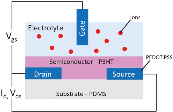
Structure of the organic electrochemical transistor.
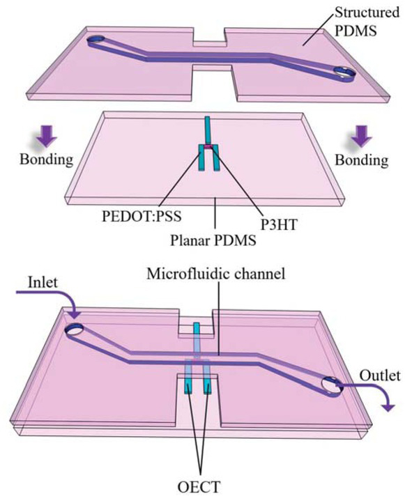
OECT-based sensor implementation into microfluidic structure.
2 Materials and methods
2.1 Materials
The mechanical properties of the microfluidic structure dictated the material choice for OECT manufacturing. Since chip „body“ is made of PDMS (DOW Silgard), the used materials for OECT must be flexible, too. Besides, the organic electrochemical transistor-based biosensor designed for organ-on-a-chip applications has tobe located in the microfluidic channel in the direct contact to cultured cells. Therefore, organic polymers have tobe applied. As a material for electrodes (source, drain and gate), the organic conductor the Poly(3,4-ethylenedioxythiophene) polystyrene sulfonate (PEDOT:PSS) (Osilla Ltd.) is applied [6]. It is a flexible and transparent conductive polymer. Due to its unique combination of conductivity, transparency, ductility, and ease of processing, PEDOT:PSS has become a benchmark material in thin-film electronic fabrication. For the active layer between source and drain the polymer semiconductor Poly(3-hexylthiophene-2,5-diyl) (P3HT, Ossila Ltd) was selected [7]. It is soluble (50 mg/ml) in chlorinated solvents such as chloroform, chlorobenzene, dichlorobenzene and trichlorobenzene. Once thin-film is performed, and the solvent is evaporated, it can be used in biosensors as a bio-semiconductor material. P3HT is known as a highly biocompatible and H+, K+ ion sensitive material [3]. The issue of the organic conductors and semiconductors is variation of the properties due to the processing and microstructuring. As an example, charge carrier mobility for P3HT (M104) is 0.12 cm2/Vs. After the mixing and spin-coating or printing, mobility can be significantly different, up to ±0.03 cm2/Vs.
2.2 OECT manufacturing and testing
The 3D conceptual arrangement of OECT with P3HT (pink colour) is shown in Fig. 2 in combination with organic conductor poly (3,4-ethylenedioxythiophene) polystyrene sulfonate (PEDOT:PSS) (blue colour). The transistors are developed on a flexible, transparent PDMS planar substrate. The structured PDMS layer was aligned and bonded on top. Therefore, it was possible to obtain simultaneously the microfluidic reservoir for electrolyte and isolation for the source and drain electrodes. The structured PDMS layer with a microfluidic channel (1mm width and 100 μm height) was obtained from the SU8-100 on a 4¨ Si master wafer by moulding technology with the following procedure. Two components of PDMS were mixed in ratio 10:1, poured on master and cured over 48 hours. Once the polymer was cured, the layer was released, cut and bonded to the non-structured PDMS with adhesive layer (liquid PDMS) and oxygen plasma surface activation (0.5mbar, 1 min). PEDOT:PSS was spin coated on planar PDMS, soft backed at 60°C over 30 min and structured by IR laser ablation (power 4W, speed 1000mm/s, frequency 50 kHz) to obtain source, drain and gate electrodes. The semiconductor P3HT (with the concentration 5mg/ml dissolved in 1,2,4-trichlorobenzene) was aerosol jet printed on the preheated 60°C PDMS substrate with prepared source, drain and gate electrodes. Measurements of the DC voltage-current relationship (VI) were performed using Keithley 2400 source meter and multi-meter by direct on-wafer probing in three-terminal configuration. The measurement setup is shown on Fig. 3. KCl solution with the concentration of 1 mol was used as an electrolyte and pumped by a pipette in the microfluidic channel. The bonding strength of the two PDMS layers (structured and planar) was analysed by burst and leakage tests. In the first case, into the microfluidic channel with one opening air is pressurised (up to 100 kPa, in steps of 5kPa). In latter, liquid is pumped through a channel with peristaltic pump (over 2h, 60 μl/min). In both cases, the bonding strength defined by a value of the pressure or time of pumping, in the moment bonding fails.
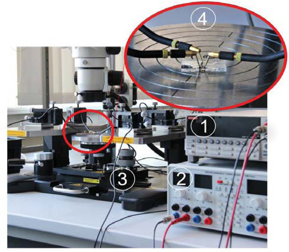
Photograph of the measurements setup: 1 - source meter, 2 - power source, 3 - probe station, 4 - magnified view on the chip on the probe station with the needles connected to source, drain and gate.
3 Results and discussion
3.1 Proof of concept
We designed, manufactured and tested an organic electrochemical transistor (OECT) based biosensor, as shown in Fig. 4. Dimensions are 3mm × 6.5mm. Only organic polymers were utilized for performing the electrodes and the active layer for OECT. With this structure, ionic concentration can be detected inside of the microfluidic channel, which serves for cell culturing. Therefore, we implemented the developed OECT on flexible substrate into a microfluidic channel (Fig. 4).
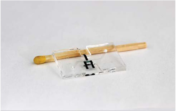
Photograph of the OECT-based biosensor integrated into a microfluidic structure.
Implementation of the transistor structure into microfluidic channel requires positioning and sealing of the two PDMS substrates (one is planar with biosensor structure, the other is the moulded microfluidic channel). By connecting the two layers, a reservoir for the OECT electrolyte was created and the insulation of the source and drain electrodes was ensured. Tight encapsulation of the microfluidic channel was possible only with a liquid adhesive layer, since it had to fill the differences in the height of the substrate and electrodes. With over two hours of pumping the liquid through the device, no leakages could be observed. Also, burst test shows, that structure is stable up to 80 kPa. As can be seen in Fig. 5, the manufactured transistors show stable volt-ampere characteristics having a saturation region. The measured curve was achieved using the electrolyte solution KCL with 1 mol concentration. The calculated curve is obtained by curve fitting using a Bernards-Malliaras (BM) model (see Section 3.2, Eq. (1)) to achieve a good correlation with the measured results.

Measured (dashed line) and calculated (continuous line) VI characteristics of the manufactured OECT.
3.2 Discussion of influence on drain current
According to the Bernards and Malliaras (BM) model [3], the drain current of an organic electrochemical transistor is given by the following expression
where μ is the carrier mobility, C is the volumetric capacitance, Vg, Vd, Vth are gate and drain and threshold voltages, respectively, and W, T, L are the channel width, thickness and length. Similarly, as in a p-channel MOS field-effect transistor, there are two operating regions: triode Vd > Vg − Vth and saturation Vd < Vg − Vth. For organ-on-chip applications, we are most interested in the saturation region, since the transistor can be operated as an amplifier and the output voltage can be used to sense deviations of ion concentration.
However, one of the major challenges for using OECT as a sensor to characterize biological response is to identify the wanted variation of the drain current due to changes of the ionic concentration of the analyte, because at the same time parameters such as threshold voltage, carrier mobility and channel capacitance also influence the measured current. Hence, this requires a more detailed analysis and calibration prior to evaluation of the measurements.
The variation of the current due to uncertainties in the mentioned parameters can be calculated using derivation of a multivariable function, as shown below
where the partial derivatives of the drain current with respect to such parameters are:
If we put the partial equations back into the original BM model, we obtain the following expression for the sensitivity of the drain current:
For easier interpretation of the results, we renormalize the measurement error to the reference value of the nominal drain current
This shows how sensitive the drain current is to manufacturing tolerances and uncertainties in material properties. Additionally, one can observe that the inaccuracy due to threshold voltage spread can contribute a very large error for small overdrive voltages (Vg− Vth).
3.3 Measurements uncertainty based on manufacturing tolerances
First, as Fig. 5 shows, measured VI characteristic (dotted line) and applied BM model (continuous line) are correlating well. Therefore, we use this measurement for calibration and benchmarking of measured versus calculated parameters. We apply the formula (4) developed in the previous section to estimate how the drain current depends on an increasing channel capacitance (10 F/cm3, 40 F/cm3, 80 F/cm3) and carrier mobility (0.1 cm2/Vs, 0.12 cm2/Vs, 0.14 cm2/Vs), neglecting the dependence on threshold voltage Vth here, since it is less affected by manufacturing tolerances. Due to direct proportionality of C and μ we can expect an increase of the current depending on both parameters. As can be seen in (Fig. 6(a)) the drain current in its saturation scales almost directly with a four or eight times higher channel capacitance. In a similar way the carrier mobility influences the drain current (Fig. 6(b)). Assuming that μ can alter by up to 0.04 cm2/ Vs within the fabrication process, a deviation of Id by about +40 μA must be expected.
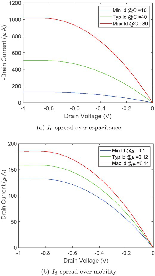
Measurement uncertainty due to deviation of channel capacitance C and carrier mobility μ.
4 Conclusions
We presented a first approach for an organic electrochemical transistor (OECT) for detecting the ion concentration inside of the microfluidic channel for cell culturing applications. Polydimethylsiloxane is used as a substrate for sensor implementation, due to its transparency and gas permeability. Using organic materials for the biosensor fabrication is beneficial, as they do not interfere with the bio substances in the microfluidic channel. However, longterm stability of these materials in the liquid (media for cell culture) is still the challenging part of the implementation. We showed implementation of the OECT into a microfluidic channel. Besides, adhesive bonding with liquid PDMS ensured sealing of the reservoir for electrolyte and isolation of the source and drain electrodes. Transistor VI characteristics measured and calculated using the Bernards model correlate well. However, variations of key parameters in the model can influence the sensor characteristics by means of the drain current significantly. Based on the channel capacitance C and the carrier mobility μ we discussed two main variables that strongly depend on material properties and manufacturing accuracy. Their impact on the sensor signal Id must be considered and is to be taken into account (e.g. sensor calibration).
Literatur
[1] Y. S. Zhang et al., Sensor-integrated organs-on-chips in Proceedings of the National Academy of Sciences, vol. 114, no. 12, pp. 2293,2302, Mar 2017Search in Google Scholar
[2] O. Andersen, Cellular electrolyte metabolism in Encyclopedia of Metalloproteins, BNID 110754, pp. 580,587, 201310.1007/978-1-4614-1533-6_223Search in Google Scholar
[3] J. T. Friedlein, R. R. McLeod, J. Rivnay, Device physics of organic electrochemical transistors in Organic Electronics, vol. 63, 2018, pp. 398-414, ISSN 1566-1199, https://doi.org/10.1016/j.orgel.2018.09.01010.1016/j.orgel.2018.09.010Search in Google Scholar
[4] M. Ghittorelli et al. High-sensitivity ion detection at low voltages with current-driven organic electrochemical transistors in Nat Commun, vol. 9, pp. 1441, 201810.1038/s41467-018-03932-3Search in Google Scholar PubMed PubMed Central
[5] R. Colucci et al., Recent advances in modeling organic electrochemical transistors in Flexible and Printed Electronics, vol. 5, no. 1, pp. 013001, 202010.1088/2058-8585/ab601bSearch in Google Scholar
[6] S. Jäckle et al., Potential of PEDOT:PSS as a hole selective front contact for silicon heterojunction solar cells in Sci Rep, vol. 7, pp. 2170, 201710.1038/s41598-017-01946-3Search in Google Scholar PubMed PubMed Central
[7] C. Rosu et al., Protein-Assisted Assembly of π-Conjugated Polymers in Chemistry of Materials, vol. 28, no. 2, pp. 573,582, 201610.1021/acs.chemmater.5b04192Search in Google Scholar
© 2020 Walter de Gruyter GmbH, Berlin/Boston
Articles in the same Issue
- Frontmatter
- Editorial
- XXXIV. Messtechnisches Symposium
- Beiträge
- Detektion der Auflagestege von Flachbett-Laserschneidmaschinen mittels Nahinfrarot-Beleuchtung
- Lichtfeld-Tiefenschätzung für die Vermessung teilspiegelnder Oberflächen
- Ganzheitliche Kalibrierung von Gewinden auf Basis eines dreidimensionalen Ansatzes
- Analyse von 3D-CT-Aufnahmen von Spänen zur Extrahierung der Segmentspanbildungsfrequenz
- Resolution enhancement through nearfield-assistance in interference microscopy
- Fertigung polymerer optischer Phasenplatten zur Erzeugung von Ringmoden mittels direkter Laserlithografie
- Direct-imaging DOEs for high-NA multi-spot confocal microscopy
- Methoden zur Minimierung des Rauscheinflusses durch Hitzeflimmern bei einem heterodynen Laser-Doppler-Vibrometer
- Inverse piezoelectric material parameter characterization using a single disc-shaped specimen
- Klassifikation von Grübchenschäden an Zahnrädern mittels Vibrationsmessungen
- Incorporation of phase information for improved time-dependent instrument recognition
- Akustische Zeitumkehrfokussierung in Wasser mittels FPGA-basierter Plattform
- De-Embedding-Ansatz zur Messung nichtidealer Kapazitäten mit kommerziellen Kapazitätssensoren
- Low-cost Indirect Measurement Methods for Self-x Integrated Sensory Electronics for Industry 4.0
- Reconfigurable Wide Input Range, Fully-Differential Indirect Current-Feedback Instrumentation Amplifier with Digital Offset Calibration for Self-X Measurement Systems
- A Compact Four Transistor CMOS-Design of a Floating Memristor for Adaptive Spiking Neural Networks and Corresponding Self-X Sensor Electronics to Industry 4.0
- Monte-Carlo-Methode zur Verringerung von Messfehlern bei der Materialparameterbestimmung mit Hohlraumresonatoren
- Bestimmung des Anregungsspektrums für kontaktlose breitbandige Messungen der Übertragungsfunktion mit Plasmaanregung und Laser-Doppler-Vibrometrie
- Self-sufficient vibration sensor for high voltage lines
- Flexibler organischer elektrochemischer Transistor als Biosensor für Organ-on-a-Chip
- Erkennung und Kompensation von Vergiftung durch Siloxane auf Halbleitergassensoren im temperaturzyklischen Betrieb