In-situ CT characterization of 2D woven SiCf/SiC composite loading under compression
-
Weina Guo
 and
Lijuan Sun
and
Lijuan Sun

Abstract
SiC fiber-reinforced SiC matrix composites (SiCf/SiC) with 2D woven fabric as preform were tested under compression with in-situ X-ray computed tomography. The microstructure and damage evolution of the material under continuous loading levels were accurately revealed by image reconstruction of CT data. There were inhomogeneous pores in SiCf/SiC composite because of the un-uniform fiber distribution in the preform. The result also showed that 2D woven SiCf/SiC composite had obvious non-linear characteristics by its compressive load–displacement curve, and the damage modes included transverse matrix cracking, interlayer cracking, longitudinal matrix cracking, and fiber bundle fracture. Matrix cracking tended to occur near the pores or holes of the material, and the number of longitudinal cracks was relatively high compared to the number of transverse cracks.
1 Introduction
SiCf/SiC composites are attractive for high-performance engineering applications due to their thermal properties, corrosion resistance, low density compared to metals, and higher toughness compared to monolithic ceramics [1–3]. Therefore, a thorough understanding of the complex damage initiation and accumulation mechanisms under typical mechanical loading conditions is essential for the safe design and practical service life prediction of SiCf/SiC composites [4,5]. One-dimensional statistical models based on matrix and fiber failure probability laws (e.g., Weibull’s law) have been well documented [6–13]. These models can make satisfactory predictions of macroscopic responses. However, they cannot be adequately validated for microscopic phenomena. In fact, even when qualitative damage evolution is accepted, most of the observations reported in the literature were confined to the surface and collected after the final failure, which does not facilitate the study of their damage process [14,15].
In-situ X-ray computed tomography (XCT) is a non-destructive testing technique developed in recent years, which enables 3D microscopic imaging of materials and can provide volumetric information about microstructure and microcrack meshes [16–18], which cannot be done by traditional microscopy techniques. Currently, some scholars [19,20] have successfully applied XCT techniques to the study of fracture failure processes of SiCf/SiC and Cf/SiC composites and comprehensively analyzed the damage processes of a variety of composites under stress loading from microstructure analysis (Table 1). Zhang et al. [21] used XCT to study the plain SiC fiber-reinforced SiC matrix composites in terms of microstructure and tensile damage evolution and developed a miniature high-precision in-situ XCT test fixture that can be used to perform miniature XCT in-situ tensile tests. Ai et al. [22] reconstructed the precise microstructure of Cf/SiC composites composed of C fiber bundles and chemical vapor infiltration (CVI)–SiC matrix, performed in-situ tensile experiments on Cf/SiC composites using a CT real-time quantitative imaging system, and investigated the damage and failure characteristics of the material, which showed that the material damage occurred first at the defects and then extended to the fiber bundle SiC matrix interface, eventually forming macroscopic cracks. Duan et al. [23] investigated the bending progressive damage behavior of 2.5D SiCf/SiC braided composites using a three-point bending method. In this process, acoustic emission and digital image correlation were used to monitor the damage progression. Subsequently, micro-CT was used to identify the internal damage evolution. It can be seen that the use of in-situ loaded CT imaging technique to study the damage failure mechanism of SiCf/SiC composites has unique advantages [24].
Examples of XCT technology applied to composites
| Composite name | Research objective | Research method | Research results |
|---|---|---|---|
| C/SiC [19] | Tensile dynamic fracture | XCT | Tensile failure: |
| Split Hopkinson pressure bar | Delamination | ||
| Fiber pullout | |||
| Bundle breaking | |||
| SiC/SiC [20] | Tensile test | XCT | A slow and discontinuous propagation of matrix cracks, even after the occurrence of matrix crack saturation. |
| Matrix crack propagation | |||
| Six successive loading levels | Observations before the ultimate failure revealed only a few fibers breaking homogeneously along the minicomposite. | ||
| Fiber breaking occurrences | |||
| SiC/SiC [21] | Tensile damage evolution | XCT | Tensile failure: |
| Transverse matrix cracking | |||
| Microstructures | Six successive loading levels | Longitudinal matrix cracking | |
| Fiber pull-outs | |||
| High-precision in-situ XCT test fixture | |||
| C/SiC [22] | In-situ tensile test | X-ray microtomography digital images | Material damage initially occurs at the defects, followed by propagating toward the fiber-tow/SiC–matrix interfaces, ultimately, combined into macro-cracks |
| Meso-structural | |||
| Finite element analysis | |||
| Damage evolution | |||
| Fracture behaviors | |||
| SiC/SiC [23] | Flexural progressive damage | XCT | 2.5D warp samples present the pseudo-ductile fracture, whereas 2.5D weft samples indicate the brittle fracture |
| Acoustic emission | |||
| Digital image correlation | |||
| Three points bending method | |||
| SiC/SiC [24] | Tensile test | XCT | Stress concentrations in the planes containing the weft tows |
| Failure events | Finite element analysis | The first cracks and subsequent damage localization were found |
However, most of the in-situ studies on the damage evolution of SiCf/SiC composites have focused on tensile damage evolution [21,25,26], while the damage process of SiCf/SiC composites under compression loading has rarely been reported. Therefore, in this article, for the damage evolution mechanism of plain SiCf/SiC composites, in-situ XCT compression tests were carried out to investigate the damage process under transverse compression loading, the damage sprouting and evolution law of SiCf/SiC composites during compression was revealed and failure behavior was analyzed.
2 Experimental
2.1 Description of SiCf/SiC composites
The specimen was fabricated by CVI process, and the toughened phase was laminated 2D plain fabric woven by third-generation SiC fiber with about 500 fibers per fiber bundle and the average diameter of single fiber was 12.6 μm. Prior to CVI process, pyrolytic carbon was deposited on the preforms by chemical vapor deposition, yielding a thickness of about 200 nm. Methyltrichlorosilane was used to deposit the SiC matrix at 1,100°C until the density of composites remained steady. Specimens with a size of 2 mm × 4 mm × 20 mm were prepared for the test.
2.2 X-ray in-situ compression test
The laboratory-based interrupted in-situ CT imaging (described as in Figure 1) was performed under compression load in The State Key Laboratory of Nonlinear Mechanics, Institute of Mechanics, Chinese Academy of Sciences. The in-situ compression test equipment is the Y.CT Modular from Yxlon, Germany. A pause of about 20 min after every loading was needed for collecting tomogram at the related stress level. In the experiments, total ten loadings were conducted until final fracture. The compression force was successively loaded up to 483.657, 1288.506, 2330.982, 2920.614, 3561.132, 4030.783, 3956.554, 3210.061, and 3262.348 N. As the requirement of sample size, the resolution of CT imaging used was selected as 9 μm.

In-situ CT compression experiment.
3 Results and discussion
3.1 Analysis of initial microstructure
The complexity of the woven structure and CVI process will lead to defects such as pores in the woven SiCf/SiC composites. First, 3D images reconstructed by CT data were used to detect the initial microstructure of SiCf/SiC composites.
3.1.1 Initial defects
Pores are one of the major defects of SiCf/SiC composites. The pores have a negative effect on the mechanical properties of the composite such as interlaminar shear strength, longitudinal and transverse bending strength, and longitudinal and transverse compression strength. Figure 2 shows the structure of the plain fabric. It can be seen that the four adjacent yarns do not closely overlap. The non-overlapping parts then form corresponding pores. The internal pores of the material can be divided into initial pores generated during the preparation process and damage cracks caused by external loading. The initial pores generated by SiCf/SiC composites are a typical feature of the plain structure and the CVI densification process and can be distinguished in the reconstructed images. Depending on the volume of the pore structure, there are two types of initial pores, namely matrix micropores within the fiber bundles and macro-pores between the fiber bundles, as shown in Figure 3 [27].

Structure of plain fabric.
![Figure 3
Distribution of initial holes on different slices: (a) XOY slice, (b) XOZ slice, and (c) YOZ slice [27].](/document/doi/10.1515/secm-2022-0166/asset/graphic/j_secm-2022-0166_fig_003.jpg)
Distribution of initial holes on different slices: (a) XOY slice, (b) XOZ slice, and (c) YOZ slice [27].
From Figure 3, it can also be seen that the micropores in 2D woven SiCf/SiC composites were mainly distributed inside the fiber bundles. By observing the pores in the fiber bundles, it was found that the micropores were distributed along the longitudinal direction of the fiber bundles. The micropores were small but large in number. Besides, there was almost no connection among the micropores. As shown in Figure 3, the large pores were mainly distributed in the non-overlapping areas of warp and weft yarns of each layer. This was because during the CVI process, the overlapping fiber yarns provided a larger surface area than the non-overlapping fiber yarns, and the matrix can be deposited rapidly in the fiber yarns. As the deposition process proceeded, the transport channels for the reaction gases gradually closed, eventually leading to the formation of large pores with low deposition rates in the non-overlapping areas. Overall, the distribution of both microporosity and large pores was irregular, but they can be clearly distinguished.
By applying threshold segmentation, variation of the porosity distribution on the slices in different directions can be clearly observed, as shown in Figure 4. From Figure 4, it can be observed that the distribution of porosity along different directional slices was not regular. In the X and Y directions, the surface fraction of porosity showed a complex variation due to the periodicity of the weaving pattern and the superimposed effect of the number of layers. This variation was due to the presence of an offset (“U”) of the weft yarns in the X-direction, while the warp yarns were aligned with each other in the Y-direction. The porosity of the composite showed significant fluctuations in the X and Y directions due to the low porosity within the plies and the high porosity between the plies. The fluctuations in the Z-direction were related to the superposition of the plies in the composite. The local minima of porosity were caused by the intermediate planes within the layers and the maxima of porosity were related to the median plane between the two layers. Similar results were also found by Gelebart et al. [28] for the characterization of porosity of CVI SiCf/SiC composites by X-ray chromatography.

Porosity distribution of slices in three different directions.
3.2 Compression test results analysis
3.2.1 Load–displacement curve
The load–displacement response of the material during loading was a macroscopic characterization of its internal damage evolution process, and Figure 5 shows the load–displacement curve at successive loading levels. From this, the curve of the sample can be divided into five stages. The first stage (OA stage): at the beginning of loading, the curve was linear, and the sample load–displacement curve increased linearly along the straight line OA, indicating that the material was in the elastic deformation stage and almost no damage occurred, and the specimen can return to its original state after unloading. The second stage (AB stage): the curve showed a non-linear change, which might be caused by the gradual internal damage and the transmission of cracks along the matrix to the fibers and between the fiber layers. The third stage (BC stage): the curve shows linearity, and the displacement gradually increases with the increase of load. At this time, the cracks on the matrix gradually extend to the fiber–matrix bonding interface (i.e., the interface layer) with the increase in load, and the interface layer, as the bridge connecting the matrix and the fiber inside the SiCf/SiC composite, was the key factor regulating the bonding strength between the fiber and the matrix. Its components and structure largely determined the mechanical properties of SiCf/SiC composites. The fourth stage (CD stage): as the load continued to increase, the slope of the curve gradually decreases. This indicates that the matrix has failed, and the stress-relieving effect of the interfacial layer has reached saturation, and cracks gradually start to sprout and expand inside the fibers. The fifth stage (DE stage): the curve was sawtooth-shaped, indicating that the matrix did not reach the ultimate load immediately after fracture, but after a “buffer period,” which was because when the load reached the matrix critical load, crack expansion, interface debonding, fiber pullout and fracture, and other toughening effect absorb part of the stress. At the same time, the stresses were released by a small mutual “slip” between the matrix grains, so that the specimen can continue to withstand the load until the final fracture.

Compressive load–displacement curve of SiCf/SiC composite.
In addition, it can be observed from Figure 5 that the whole evolution of the load–displacement curve of the sample showed brittle fracture characteristics, which was due to the fact that the matrix was mainly loaded during compression, thus the load increased more slowly with displacement during the elastic deformation phase, and the material has a lower modulus of elasticity in parallel compression, and once the ultimate load that the matrix can withstand was exceeded, the matrix fractures or crushes and the curve drops steeply, leading to the destruction of the material.
3.2.2 Damage evolution process
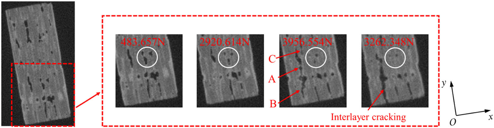
The 3D reconstructed CT data under different loading states (the state 2: 483.657 N, the state 5: 2920.614 N, the state 8: 3956.54 N, and the state 10: 3262.348 N) were selected to visualize and analyze the microstructure morphology of the material during the compression process by using software “AVIZO 9.1” to observe the damage change information such as internal pore distribution, crack initiation, and size change of the material during the compression process.
The internal damage process of SiCf/SiC composites during compression was obtained by observing the internal tomography of the material perpendicular to the three coordinate axes. Figure 6 shows a set of local CT 2D sections on the frontal ZOY section of the test piece. In the first loading condition, no damage was observed within the fiber matrix. In the fourth loading condition, there were two transverse cracks perpendicular to the compression direction. The crack indicated by the arrow in A occurs at the fiber bundle lap boundary, which was connected to the large hole and belonged to the matrix crack outside the fiber bundle. And the crack with the B arrow was a transverse crack of the matrix inside the weft fiber bundle. Longitudinal cracking parallel to the fiber direction occurs at loading condition 7, which started at the edge of the large matrix hole and extended inside the fiber bundle, and this longitudinal cracking was also observed in the cross-section at other locations inside the test piece. The longitudinal crack extension path related to the cracks at positions A and B (described in Figure 6) led to the fracture of the fiber bundle surrounded by the transverse and longitudinal cracks. Under the tenth loading condition, the test piece was already partially crushed, the longitudinal crack did not occur too close and the hole at the fracture of the fiber bundle became larger.

Damage evolution process of local area on ZOY cross-section.
Figure 7 shows a set of local CT 2D sections on the ZOX cross-section of the side of the test piece. At the seventh loading, the cracks inclined to the compression direction can be clearly seen. As described in the figure, the crack at position A started from the large hole in the matrix and it extended from the hole to the inside of the fiber bundle and gradually parallel to the fiber bundle. The crack at B was a longitudinal crack inside the fiber bundle, which started from the edge of the test piece and extended to the inside of the test piece. In addition, a significant interlaminar cracking within the matrix between the two adjacent fiber bundles at the seventh loading condition was observed, where the cracking started from the hole, and the interlaminar cracking was almost parallel to the nearby fiber bundles. After the test piece was crushed, the interlaminar cracking was more pronounced and more longitudinal cracks appeared inside the fiber bundles than in the seventh loading condition.

Damage evolution process of local area on ZOX cross-section.
Figure 8 shows a set of local CT 2D sections on the YOX cross-section of the test piece. No obvious changes were produced at the fourth loading, and there was a tendency for the local pores to shrink, and some of the micropores almost disappeared by the compression to the ninth loading. The cracks at positions A and B started from the holes and extended in a direction almost parallel to the weft fiber bundle, and the end of the cracks at position A extended to the beginning of the cracks at position B. The cracks at position B extended to the edge of the test piece and finally formed matrix cracks between the two layers, causing interlayer cracking. There were more voids, less matrix, and weaker interlayer connection at this place, so after the cracks sprouted under the seventh loading condition, the cracks gradually expanded as the pressure increased. By the ninth loading, the interlaminar cracking was so severe that the fiber bundles between the left and right of the interlaminar matrix separated.
Damage evolution process of local area on YOX section.
Figure 9 shows the strain distribution calculated by digital volume correlation (DVC) under the maximum loading condition. Figure 9(a–c) shows the strains in the X, Y, and Z directions, respectively (Z direction is the loading direction). From the figures, the strain was not uniform, and the variation in the Y and Z directions was more serious than that in the X direction, and there was a serious strain concentration in the lower part of the test piece. Although the test piece was subjected to unidirectional compression load in the experiment, the internal stress state and deformation behavior were non-uniform and the complex stress/strain states due to the complexity of the material microstructure. The most severe deformation at the interlaminar crack can be observed in the lower part of the strain concentration, where one of the sides of the interlaminar crack moved outward, resulting in a significant change in its displacement in the X, Y, and Z directions, as shown in Figure 10. It was observed that the distribution of the displacement showed inhomogeneity, and its significant changes also occurred mainly in the stress concentration part. Therefore, the strain concentration had a significant effect on the displacement variation of the specimen.

Strain distribution under maximum loading calculated by DVC: (a) X-direction, (b) Y-direction, and (c) Z-direction.

Displacement variation under maximum loading calculated by DVC: (a) X-direction, (b) Y-direction, and (c) Z-direction.
3.2.3 Failure mechanisms
According to damage evolution of the material, it was found that the 2D woven SiCf/SiC composites mainly experienced damage modes such as matrix transverse cracking, interlayer cracking, fiber bundle matrix longitudinal cracking, and fiber bundle fracture from the beginning of damage to final failure.
3.2.4 Transverse matrix cracking
Since the fracture strain of the matrix was small, transverse cracks in the matrix perpendicular to the compression direction occurred first during the compression process, which were mainly divided into transverse cracks in the matrix outside the fiber bundle and transverse cracks in the matrix inside the fiber bundle (Figure 6). Matrix cracks in the fiber bundle mainly occurred in the weft direction, and many transverse cracks evolved from the development of microvoids in the fiber bundle. Due to the presence of a weak interfacial layer in the fiber, these transverse cracks generally extended along the interface and did not cause fiber fracture. Matrix cracks outside the fiber bundle mainly occurred at the fiber lap boundary, near the large holes in the matrix, and at the edges of the material, where the holes disrupted the continuity of the material and produced stress concentrations that promoted damage cracking.
3.2.5 Interlaminar cracking
As the loading increased, interlaminar cracking gradually appeared in the matrix between the bundles (Figure 7). Interlaminar cracking mostly sprouted at the edge of large holes and developed along the intersection of fiber bundles and the external matrix, and because the direction of interlaminar cracking was almost parallel to the adjacent fibers, it was not easy to enter the interior of fiber bundles in expansion, but was continuous within the matrix between the fiber layers, resulting in delamination of the material. In regions where interlaminar cracking was more severe, it can lead to separation of the interlaminar matrix from the fiber bundles on both the sides.
3.2.6 Longitudinal cracking of fiber bundles
The causes of longitudinal cracking inside the fiber bundles were more complex and were less likely to occur before material damage. The geometric characteristics of fiber bundles, their arrangement, and initial defects led to the susceptibility to stress concentration and longitudinal cracks along the ZOY plane inside the bundles (Figure 7); the fiber bundles were wavy, and the bundles were bent at the same time during the compression process, and the compression deformation of the upper and lower parts of the bundles was different in the longitudinal direction, which was prone to longitudinal cracks along the ZOX plane (Figure 6). It can be seen that when the compression load does not reach the strength limit of the composite, compression damage was resisted together by the fiber and matrix in the composite, and the damage modes were matrix cracking, delamination, and fiber bundle cracking.
3.2.7 Fiber bundle fracture
Fiber bundle fracture occurs as the composite reaches its strength limit, and the sudden release of the potential energy accumulated in the composite under compression causes a serious separation of the fiber bundle from the matrix. Thus, part of the fiber bundles fracture and cracks appear. When the fiber bundle breaks, the friction between the fiber bundle and the matrix can effectively absorb the energy generated by the compression load. At the same time, the fracture of the fiber bundle weakens the ability of the composite to resist damage. With the appearance of a large number of fiber fractures, composite loses the ability to continue to resist damage, and failure occurs finally.
4 Conclusion
In this article, we characterized the microstructure of 2D woven SiCf/SiC composite using synchronous radiation X-ray computed tomography and investigated the damage evolution of the material under compression by in-situ CT experiment and discussed the damage evolution and failure mechanism of 2D woven SiCf/SiC composites. The main conclusions are as follows:
XCT can better reveal the microstructure, porosity distribution, and damage evolution of 2D SiCf/SiC composite. The distribution of the initial porosity along the different directional slices has obvious irregularity. The micropores produced during the manufacturing process were small but large in number and distributed along the fiber bundles, and the large pores were mainly distributed in the overlapping areas of the warp and weft direction filament bundles.
The load–displacement curves of SiCf/SiC composite showed obvious non-linear characteristic curves, and the damage mainly occurred in the second, third, and fourth stages. The damage modes mainly included transverse matrix cracking, interlaminar cracking, longitudinal matrix cracking, and fiber bundle fracture.
Matrix cracks tended to occur near the pores or holes of the material, and the number of longitudinal cracks was relatively high compared to the number of transverse cracks.
It is recommended that preform of the composite can be optimized and denser composites will be preferable to improve their mechanical properties. Besides, numerical simulation can also be implemented to verify the failure mechanisms concluding from the experiments.
-
Funding information: The work was supported by the National Natural Science Foundation of China (Grant No. 11802317) and the Project of Research Group on Advanced Textile Structural Composites (Grant No. QNTD202111).
-
Conflict of interest: Authors state no conflict of interest.
References
[1] Yajima S, Hayashi J, Omori M, Okamura K. Development of a silicon carbide fibre with high tensile strength. Nature. 1976;261:683–5.10.1038/261683a0Search in Google Scholar
[2] Yajima S, Hasegawa Y, Okamura K, Matsuzawa T. Development of high tensile strength silicon carbide fibre using an organosilicon polymer. Nature. 1978;273:525–7.10.1038/273525a0Search in Google Scholar
[3] Mungiguerra S, Cecere A, Savino R, Saraga F, Monteverde F, Sciti D. Improved aero-thermal resistance capabilities of ZrB2-based ceramics in hypersonic environment for increasing SiC content. Corros Sci. 2021;178:109067.10.1016/j.corsci.2020.109067Search in Google Scholar
[4] Croom BP, Xu P, Lahoda EJ, Deck CP, Li X. Quantifying the three-dimensional damage and stress redistribution mechanisms of braided SiC/SiC composites by in situ volumetric digital image correlation. Scr Mater. 2017;130:238–41.10.1016/j.scriptamat.2016.12.021Search in Google Scholar
[5] Arai Y, Aoki Y, Kagawa Y. Effect of cristobalite formation on the delamination resistance of an oxide/Si/(SiC/SiC) environmental barrier coating system after cyclic high temperature thermal exposure. Scr Mater. 2017;139:58–62.10.1016/j.scriptamat.2017.06.006Search in Google Scholar
[6] Baxevanakis C, Jeulin D, Renard J. Fracture statistics of a unidirectional composite. Int J Fract. 1995;73:149–81.10.1007/BF00055726Search in Google Scholar
[7] Hui CY, Phoenix SL, Ibnabdeljalil M, Smith RL. An exact closed-form solution for fragmentation of Weibull fibers in a single filament composite with applications to fiber-reinforced ceramics. J Mech Phys Solids. 1995;43:1551–85.10.1016/0022-5096(95)00045-KSearch in Google Scholar
[8] Lissart N, Lamon J. Damage and failure in ceramic matrix minicomposites: experimental study and model. Acta Mater. 1997;45:1025–44.10.1016/S1359-6454(96)00224-8Search in Google Scholar
[9] DiBenedetto AT, Gurvich MR. Statistical simulation of fiber fragmentation in a single-fiber composite. Compos Sci Technol. 1997;57:543–55.10.1016/S0266-3538(97)00008-0Search in Google Scholar
[10] Curtin WA, Ahn BK, Takeda N. Modeling brittle and tough stress–strain behavior in unidirectional ceramic matrix composites. Acta Mater. 1998;46:3409–20.10.1016/S1359-6454(98)00041-XSearch in Google Scholar
[11] Lamon J. Stochastic approach to multiple cracking in composite systems based on the extreme-values theory. Compos Sci Technol. 2009;69:1607–14.10.1016/j.compscitech.2009.03.009Search in Google Scholar
[12] Castelier E, Gélébart L, Lacour C, Lantuéjoul C. Three consistent approaches of the multiple cracking process in 1D composites. Compos Sci Technol. 2010;70:2146–53.10.1016/j.compscitech.2010.08.014Search in Google Scholar
[13] Phoenix SL. Statistical issues in the fracture of brittle-matrix fibrous composites. Compos Sci Technol. 1993;48:65–80.10.1016/0266-3538(93)90121-VSearch in Google Scholar
[14] Bertrand S, Forio P, Pailler R, Lamon J. Hi-Nicalon/SiC minicomposites with (pyrocarbon/SiC)(n) nanoscale multilayered interphases. J Am Ceram Soc. 1999;82:2465–73.10.1111/j.1151-2916.1999.tb02105.xSearch in Google Scholar
[15] Martinez-Fernandez J, Morscher GN. Room and elevated temperature tensile properties of single tow Hi-Nicalon, carbon interphase, CVI SiC matrix minicomposites. J Eur Ceram Soc. 2000;20:2627–36.10.1016/S0955-2219(00)00138-2Search in Google Scholar
[16] Stock SR. Recent advances in X-ray microtomography applied to materials. Int Mater Rev. 2008;53:129–81.10.1179/174328008X277803Search in Google Scholar
[17] Maire E, Withers PJ. Quantitative X-ray tomography. Int Mater Rev. 2014;59:1–43.10.1179/1743280413Y.0000000023Search in Google Scholar
[18] Croom BP, Xu P, Lahoda EJ, Deck CP, Li X. Quantifying the three-dimensional damage and stress redistribution mechanisms of braided SiC/SiC composites by in situ volumetric digital image correlation. Scr Mater. 2017;130:238–41.10.1016/j.scriptamat.2016.12.021Search in Google Scholar
[19] Li T, Fan D, Lu L, Huang JY, Zhao JCE, Qi F, et al. Dynamic fracture of C/SiC composites under high strain-rate loading: microstructures and mechanisms. Carbon. 2015;91:468–78.10.1016/j.carbon.2015.05.015Search in Google Scholar
[20] Chateau C, Gelebart L, Bornert M, Crépin J, Boller E, Sauder C, et al. In-situ X-ray microtomography characterization of damage in SiC/SiC minicomposites. Compos Sci Technol. 2011;71:916–24.10.1016/j.compscitech.2011.02.008Search in Google Scholar
[21] Zhang DX, Liu Y, Liu HL, Feng YQ, Guo HB, Hong ZL, et al. Characterisation of damage evolution in plain weave SiC/SiC composites using in situ X-ray micro-computed tomography. Compos Struct. 2021;275:114447.10.1016/j.compstruct.2021.114447Search in Google Scholar
[22] Ai SG, Song W, Chen YF. Stress field and damage evolution in C/SiC woven composites: image-based finite element analysis and in situ X-ray computed tomography tests. J Eur Ceram Soc. 2021;41:2323–34.10.1016/j.jeurceramsoc.2020.12.026Search in Google Scholar
[23] Duan YD, Qiu HP, Yang TT, Wang L, Wang XM, Xie WJ, et al. Flexural failure mechanism of 2.5D woven SiCf/SiC composites: combination of acoustic emission, digital image correlation and X-ray tomography. Compos Commun. 2021;28:100921.10.1016/j.coco.2021.100921Search in Google Scholar
[24] Mazars V, Caty O, Couégnat G, Bouterf A, Roux S, Denneulin S, et al. Damage investigation and modeling of 3D woven ceramic matrix composites from X-ray tomography in-situ tensile tests. Acta Mater. 2017;140:130–9.10.1016/j.actamat.2017.08.034Search in Google Scholar
[25] Yang HT, Xu SH, Zhang DX, Li LB, Huang XZ. In-situ tensile damage and fracture behavior of PIP SiC/SiC minicomposites at room temperature. J Eur Ceram Soc. 2021;41:6869–82.10.1016/j.jeurceramsoc.2021.06.050Search in Google Scholar
[26] Quiney Z, Weston E, Nicholson PI, Pattison S, Bache MR. Volumetric assessment of fatigue damage in a SiCf/SiC ceramic matrix composite via in situ X-ray computed tomography. J Eur Ceram Soc. 2020;40:3788–94.10.1016/j.jeurceramsoc.2020.04.037Search in Google Scholar
[27] Gao, YT, Wang YD, Yang XM, Liu M, Xia, HH, Huai P, et al. Synchrotron X-ray tomographic characterization of CVI engineered 2D-woven and 3D-braided SiCf/SiC composite. Ceram Int. 2016;42:17137–47.10.1016/j.ceramint.2016.08.001Search in Google Scholar
[28] Gelebart L, Chateau C, Bornert M, Crepin J, Boller E. X-ray tomographic charaterization of the macroscopic porosity of chemical vapor infiltration SiCf/SiC composites: effects on the elastic behavior. Int J Appl Ceram Technol. 2010;7:348–60.10.1111/j.1744-7402.2009.02470.xSearch in Google Scholar
© 2022 Weina Guo et al., published by De Gruyter
This work is licensed under the Creative Commons Attribution 4.0 International License.
Articles in the same Issue
- Regular Articles
- Experimental investigations of a novel pressure microfoam preparation device for dust removal
- Influence of hydrothermal aging on the mechanical performance of foam core sandwich panels subjected to low-velocity impact
- Experimental study on surface wrapping strengthening of EPS particles and its concrete performance
- Modification of mechanical properties of Shanghai clayey soil with expanded polystyrene
- A new EPS beads strengthening technology and its influences on axial compressive properties of concrete
- A novel superabsorbent material based on soybean straw: Synthesis and characterization
- Use of line laser scanning thermography for the defect detection and evaluation of composite material
- Research on back analysis of meso-parameters of hydraulic cemented sand and gravel based on Box-Behnken design response surface
- Hot deformation behavior and microstructure of a 0.5 wt% graphene nanoplatelet reinforced aluminum composite
- Analysis of electromagnetic characteristics of the proposed composite four-rail electromagnetic launcher
- Preparation and characterization of a graphene hybridizing polyurethane damping composite
- Effects of layup parameters and interference value on the performance of CFRP–metal interference fit joints
- Vibration and noise reduction of pipelines using shape memory alloy
- Finite element analysis of behavior and ultimate strength of composite column
- Dynamic response of functionally graded plate under harmonic load with variable gradient parameters
- Deformation behavior of rubber composite based on FEA and experimental verification
- Effects of Z-pin on moisture absorption property and damage mode under flexural load for carbon fiber composite
- Design and testing of a smart rubber stave for marine water-lubricated bearings
- Study of carbon nano-modifier of fly ash in cement concrete mixtures of civil engineering
- Analysis of multiple impact tests’ damage to three-dimensional four-directional braided composites
- Theoretical analysis of aluminum honeycomb sandwich panel supported by reinforced concrete wall under low-speed impact load
- Effects of local fiber discontinuity on the fatigue strength parameter at the fiber inclusion corner in fiber-reinforced composites
- Experimental investigation on compressive properties of three-dimensional five-directional braided composites in hygrothermal environment
- Failure process of steel–polypropylene hybrid fiber-reinforced concrete based on numerical simulations
- A simple method for measuring the monofilament diameter of continuous filament yarn with high bending stiffness via synthetic laser imaging
- Span length effect on flexural properties of composite laminate reinforced with a plain weave carbon fiber fabric in a polymer matrix
- Mechanical properties improving and microstructure characterization of inorganic artificial stone binder
- Effect of thermal treatment process on the structure of C/SiO2 composite aerogels
- Mechanical and corrosion resistance analysis of laser cladding layer
- Wear and corrosion mechanisms of Ni–WC coatings modified with different Y2O3 by laser cladding on AISI 4145H steel
- Damage and failure analysis of composite stiffened panels under low-velocity impact and compression after impact with damp-heat aging
- In-situ CT characterization of 2D woven SiCf/SiC composite loading under compression
- Effect of the manufacturing process on the equivalency qualification of glass fiber reinforced polymer
- Study of concrete properties based on crushed stone sand mixture and fiber of fly ash of thermal power plants
- Establishment of wear mechanism distribution diagram of ZTAp-reinforced iron matrix composites
- Calculation method of elastic modulus for carbon fiber-reinforced plastics considering inhomogeneous interphase
- An experimental study on the failure and enhancement mechanism of bolt-strengthening GFRP T-joint subjected to tensile loading
- The viability of cell that encapsulated in calcium alginate hydrogel beads
- Discussion of ceramic bar reinforced TWIP steel composite structure
- A theoretical framework underlying an accelerated testing method and its application to composites under constant strain rates and fatigue loading
- Theoretical analysis of interfacial design and thermal conductivity in graphite flakes/Al composites with various interfacial coatings
- Multiscale heat conduction and fractal oxidation behaviors of needle-punched carbon/carbon composites
- Numerical simulation of composite grid sandwich structure under low-velocity impact
- Wear properties of Al/TiO2 composites fabricated via combined compo-casting and APB process
- Review Articles
- Application of melanin as biological functional material in composite film field
- Review on research progress of cemented sand and gravel dam
- Communication
- Fabrications and microstructure analysis of cobalt-based coatings by an easy-coating and sintering process
- Letter to the Editor
- Investigation on mechanical and conductive behaviors of nano-graphite-based concrete