Span length effect on flexural properties of composite laminate reinforced with a plain weave carbon fiber fabric in a polymer matrix
-
Jerzy Marszałek


Abstract
This article focuses on an experimental study of the flexural response of a polymer composite laminate (CL) reinforced with a plain weave carbon fiber fabric. The aim of this research is to investigate the effect of the span length-to-specimen thickness ratio on the flexural properties of the selected CL. The laminate specimens were tested in the three-point flexure configuration for span length-to-specimen thickness ratios of 16, 20, 32, 40 and 60. The investigations were carried out to identify on-axis and 45° off-axis flexural responses of the CL. For this reason, two types of rectangular flat specimens were prepared, differing in reinforcement orientation relative to the support span. Using the special code, the lay-up of the specimens was designated as [(0/90)F]8 and [±45 F]8, respectively. It was found that the flexural modulus and flexural strength of the specimens depend on the span length-to-specimen thickness ratio. Despite testing the same CL, the response of the specimens to the change in the span length is different. In addition, it was concluded that the span length also has a significant influence on the final failure of the laminate specimens.
1 Introduction
Polymer-matrix composite laminates (CLs) (further referred to as laminates) are structural materials in which the reinforcement in the form of continuous fibers, roving fabrics, chopped strand mats or roving prepregs is stacked and impregnated with a polymer matrix [1,2]. The main advantages of laminates are high modulus of elasticity, high strength, relatively low density, high strength-to-weight ratio and corrosion resistance [3,4]. In addition, the mechanical properties of laminates can be shaped by the selection of fibers material, type of reinforcement, layers orientation and stacking sequence [5]. For this reason, laminates are used in various technical fields, especially in aerospace [6,7], automotive [8,9] and marine [10,11] industries. Bidirectional laminates reinforced with balanced plain weave carbon fiber fabrics have particular importance in the construction of lightweight and durable composite structures. These materials offer a maximum extent of strength enhancement in both longitudinal and transverse directions [12]. Besides, plain weave fabrics have good formability characteristics [13,14] and good stability [15]. Furthermore, there is a wide selection of carbon fibers that differ from each other in many aspects, such as stiffness and tensile strength [16]. An important factor determining the usefulness of laminates in engineering practice is their flexural response [17]. Laminate parts constituting components of larger engineering structures are generally thin-walled, and flexure is the dominant mode of loading. It is then necessary to determine the flexural properties of the laminate, which include flexural modulus E f and flexural strength σ f . One of the most common testing methods to study the flexural properties of materials is the three-point flexure test [18]. The flexural properties of laminates are studied using rectangular flat specimens with a length l, width b and thickness h (Figure 1a). The test can be characterized by five quantities, i.e., span length s, support radius rs , loading pin radius rp , flexural force F and deflection of the specimen δ under the loading pin at midspan (Figure 1b).

(a) Shape and dimensions of typical flexure specimen and (b) three-point flexure loading configuration.
Most often, the three-point flexure test of laminate is carried out in such a way that the main axis of the laminate (i.e., the axis indicating the direction of the highest tensile modulus) is parallel to the support span – flexural response determined in this configuration can be denoted as an on-axis flexural response. In this configuration, laminates show very good flexural properties. The on-axis flexural response of bidirectional laminates reinforced with balanced plain weave carbon fiber fabrics is studied when the weft and warp of fabric in reinforcement layers are parallel and perpendicular to the support span, respectively. However, before proceeding to design a laminated structure, it may be necessary to examine the off-axis flexural response of the laminate. In this configuration, the main axis is not parallel to the support span and the laminate shows lower stiffness and lower flexural strength. The off-axis flexural response of bidirectional laminates reinforced with balanced plain weave carbon fiber fabrics should be tested when weft and warp form an angle of 45° related to the support span due to the less reinforcement effect of the fibers. In this case, the flexural response can be denoted as 45° off-axis flexural response. The three-point flexure test of laminates should be carried out using the appropriate span length-to-specimen thickness ratio (s/h) – Figure 1. For example, the ASTM D7264 standard recommends span length-to-specimen thickness ratios of 16:1, 20:1, 32:1, 40:1 and 60:1. A sufficiently large (s/h) ratio is the reason why failures of laminate specimens occur in the outer layers only due to the bending moment [19,20,21]. The use of a relatively long support span allows us to minimize the influence of shear deformation in the specimen and thus obtain an accurate (true) flexural modulus [21].
The influence of (s/h) ratio on flexural response has been tested in the cases of unidirectional carbon and glass fiber laminates [22,23,24], bidirectional glass and carbon fiber laminates [23], glass fabric laminates [25] and unidirectional hybrid laminates [26,27,28]. However, studies [22,23,24,25,26,27,28] indicate that laminates show different flexural responses depending on (s/h) ratio. Therefore, it is impossible to establish one value of (s/h) ratio for the determination of accurate flexural modulus for different types of laminates.
However, literature is scant on the influence of the (s/h) ratio on the flexural response of bidirectional laminates reinforced with balanced plain weave carbon fiber fabrics, especially in the 45° off-axis configuration. The investigations presented in work [22] focus on the flexural properties of bidirectional woven laminate at span lengths ranging from 20 to 60 mm, but there are no studies on the 45° off-axis flexural response. In ref. [23], the subject of study is the flexural test of bidirectional carbon prepreg laminates at a different (s/h) ratio also without the 45° off-axis flexural response. Three-point flexure test of laminate made from a carbon plain weave fabric in both on-axis and 45° off-axis configuration is presented in ref. [29] but the influence of (s/h) ratio on flexural response is not studied – just one value of (s/h) ratio less than 16 is used.
It follows that there is no comparison between the on-axis and 45° off-axis flexural responses of bidirectional laminates reinforced with balanced plain weave carbon fiber fabric at different values of (s/h) ratio. There is also no information on whether the value of (s/h) ratio allowing us to determine the true on-axis flexural modulus is suitable for determining the true 45° off-axis flexural modulus of the same laminate. This is important in engineering design because the application of an inappropriate (s/h) ratio can lead to underestimation or overestimation of the values of flexural modulus and flexural strength of the laminate. Therefore, it is necessary to investigate the effect of span length-to-specimen thickness ratio (s/h) on both on-axis and 45° off-axis flexural responses of laminate specimens manufactured under the same conditions.
This study aims to evaluate the effect of (s/h) ratio on the on-axis and 45° off-axis flexural properties of bidirectional laminate reinforced with balanced plain weave carbon fiber fabric, which includes determination of flexural modulus and strength and identification of failure mechanism after completion of the tests. It is important to establish whether the value of (s/h) ratio allowing us to determine the true on-axis flexural modulus is suitable for determining the true 45° off-axis flexural modulus. The aim of this study is also to find out what useful information can be obtained using the three-point flexure test in the on-axis and 45° off-axis configurations. These results can be useful in planning the on-axis and off-axis flexure tests of bidirectional laminates which are reinforced with plain weave fabrics.
2 Materials and methods
2.1 Materials
The laminate was made from balanced plain weave 3k carbon roving fabric (3,000 filaments per roving), and the architecture of which is shown in Figure 2. This fabric has a specific coordinate axis system. The weft (along 1-axis) and the warp (along 2-axis) contain filaments made from carbon fibers classified as a general-purpose grade, whose elastic modulus and tensile strength are around 100 GPa and 1,000 MPa, respectively [16]. This fabric is also characterized by an areal density of 220 g/m2 and repeated unit cell (RUC) with dimensions of approximately 2 mm × 2 mm. The matrix is a mixture of epoxy resin MGS® LR 285 and hardener MGS® LH 285 in a 100:40 mix ratio by weight.

Architecture of the selected plain weave carbon roving fabric.
2.2 Fabrication of CL specimens
The laminate was prepared in the form of a flat plate using the hand lay-up technique (Figure 3). For this purpose, a specific mold tool was used, consisting of a steel base plate with working surface dimensions of 250 mm × 400 mm and a steel compression platen, which creates a pressure of 0.01 MPa on the working surface. The preparation of the laminate plate consisted in stacking of eight fabric layers in the mold tool. Each fabric layer was impregnated with the polymer matrix in an amount corresponding to the weight of the fabric layer. All the layers were arranged in the same way, which resulted in the creation of a bidirectional laminate plate. After the lamination process, the stack of eight impregnated fabric layers was pressed by the compression platen. The curing process of the laminate plate was divided into two steps. First, the laminate plate was cured at room temperature for 24 h in the closed mold tool. After this time, the laminate plate was taken out from the mold tool and post-cured at a temperature of 80°C for 5 h. The manufactured laminate plate showed a nominal thickness of 2.20 ± 0.01 mm and a fiber volume fraction of 52.3 ± 0.5%.

Schematic illustration of the preparation of CL specimens.
Then, two types of rectangular flat laminate specimens were cut out from the plate using water-jet cutting. The difference between specimens is presented in Figure 4, where the x-axis (longitudinal direction) and y-axis (transverse direction) define the specimen coordinate system, whereas 1-axis (along the weft) and 2-axis (along the warp) define the fabric coordinate system. In the on-axis specimens designated as [(0/90)F]8, 1- and 2-axis of each layer are parallel to the x- and y-axis, respectively (Figure 4a). In the 45° off-axis specimens designated as [±45 F]8, all reinforcement layers are rotated by 45° (Figure 4b). It means that 1- and 2-axis form an angle of 45° related to the x- and y-axis, respectively. The flexural response of the specimens was tested at five different (s/h) ratios, i.e., 16, 20, 32, 40 and 60. In order to simplify the identification of the specimens, specific denotations are used in this study. The on-axis specimens (Figure 4a) are denoted in short by CL⊞(s/h), where individual elements mean as follows: CL – short for composite laminate, ⊞ – graphical representation of the lay-up [(0/90)F]8, (s/h) – span length-to-specimen thickness ratio used in a flexure test. For example, specimens tested at (s/h) ratio of 16 are denoted as CL⊞(16). In the case of the 45° off-axis specimens (Figure 4b), the graphical element ⊞ is replaced by the symbol ⊠ (e.g., CL⊠(16)). A total of 25 specimens of CL⊞(s/h) and CL⊠(s/h) types were prepared (five specimens for each (s/h) ratio). Table 1 lists the three-dimensional sizes of all prepared specimens.
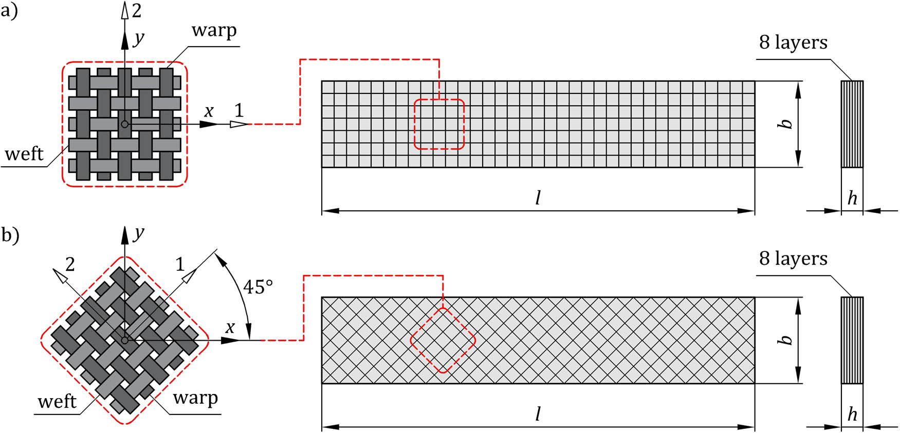
Structure and dimensions of the flexural specimens. (a) On-axis laminate specimen and (b) 45° off-axis laminate specimen.
Types and dimensions of the CL specimens
| Lay-up | Denotation | Number of specimens | Dimensions (mm) | ||
|---|---|---|---|---|---|
| Total length (l) | Width (b) | Thickness (h) | |||
| On-axis specimens [(0/90)F]8 | CL⊞(16) | 5 | 50 | 15.08 ± 0.04 | 2.20 ± 0.01 |
| CL⊞(20) | 5 | 60 | |||
| CL⊞(32) | 5 | 100 | |||
| CL⊞(40) | 5 | 120 | |||
| CL⊞(60) | 5 | 160 | |||
| 45° off-axis specimens [±45 F]8 | CL⊠(16) | 5 | 50 | ||
| CL⊠(20) | 5 | 60 | |||
| CL⊠(32) | 5 | 100 | |||
| CL⊠(40) | 5 | 120 | |||
| CL⊠(60) | 5 | 160 | |||
2.3 Three-point flexure test procedure
The three-point flexure tests were carried out on the Inspekt Table Blue 5 universal mechanical testing machine with a maximum measuring capacity of 5 kN. The radius of the loading pin and supports was 5 and 2 mm, respectively. The flexure test configuration is shown in Figure 5a. During the test, the specimen deflection δ(t) at the midspan loading point, defined as a vertical displacement of the crosshead, was applied at a speed of 1 mm/min (increasing linearly with time t), and the vertical force F(δ) defined as a reaction force on the load cell was measured (at an instant t 0, the loading pin is in contact with the specimen and the deflection is equal to zero). The tests were carried out for five different (s/h) ratios, i.e., 16, 20, 32, 40 and 60 – such values are included in the ASTM D7264 standard [19]. A total of 25 on-axis specimens and 25 45° off-axis specimens were tested (five specimens for each (s/h) ratio). Figure 5b shows some examples of the specimens placed in the three-point flexure test fixture for different (s/h) ratios. The tests were carried out at room temperature. For each specimen, the force–deflection curve was recorded, and the failure mechanism was identified by visual inspection after the completion of the test.

(a) Schematic diagram of flexural testing setup and (b) photographs of the specimens tested at different (s/h) ratios.
3 Results and discussion
The experimental data obtained from the three-point flexural tests are presented in the form of force–deflection curves F(δ). Figure 6 shows the force–deflection curves for the on-axis specimens for different values of (s/h) ratio. The flexural response of the 45° off-axis specimens is presented in the same way in Figure 7. The flexural modulus E
f
and the flexural strength σ
f
were determined based on the experimental data (Table 2) – the asterisk symbol indicates an approximate value, which is caused by the sliding behavior of the contact point between the specimens and supports. According to refs [21,30], the flexural modulus was calculated in each case by equation (1) taking into account the force F and deflection δ corresponding to the initial linear slope of the force–deflection curve. The values of the flexural strength were in turn determined by using equation (2), wherein deflection

Flexural force–deflection responses of the on-axis specimens for various values of (s/h) ratio.

Flexural force–deflection responses of the 45° off-axis specimens for various values of (s/h) ratio.
Results of the three-point flexure tests
| Specimen number | (s/h) ratio | On-axis laminate specimens | 45° off-axis laminate specimens | ||||||
|---|---|---|---|---|---|---|---|---|---|
|
|
|
|
|
|
|
|
|
||
| 1 | 16 | 41.87 | 41.23 ± 0.37 | 758.2 | 738.4 ± 19.8 | 12.08 | 12.26 ± 0.21 | 362.4 | 357.8 ± 10.1 |
| 2 | 40.98 | 761.2 | 12.27 | 349.7 | |||||
| 3 | 41.05 | 718.9 | 12.61 | 356.4 | |||||
| 4 | 41.24 | 723.8 | 12.19 | 372.6 | |||||
| 5 | 41.01 | 729.8 | 12.17 | 347.8 | |||||
| 1 | 20 | 43.26 | 42.59 ± 0.81 | 771.5 | 773.4 ± 19.4 | 12.32 | 12.35 ± 0.14 | 287.8 | 297.5 ± 5.6 |
| 2 | 42.73 | 748.7 | 12.25 | 299.2 | |||||
| 3 | 43.09 | 785.3 | 12.53 | 300.9 | |||||
| 4 | 41.22 | 762.8 | 12.18 | 301.2 | |||||
| 5 | 42.64 | 798.5 | 12.46 | 298.5 | |||||
| 1 | 32 | 43.75 | 43.58 ± 0.48 | 678.9 | 682.8 ± 22.1 | 11.16 | 11.36 ± 0.30 | *208.4 | *207.1 ± 1.8 |
| 2 | 43.16 | 646.9 | 11.44 | *209.4 | |||||
| 3 | 43.36 | 700.8 | 11.54 | *204.9 | |||||
| 4 | 44.34 | 687.1 | 10.97 | *206.3 | |||||
| 5 | 43.28 | 700.2 | 11.71 | *206.5 | |||||
| 1 | 40 | 46.12 | 45.36 ± 0.86 | 739.5 | 761.2 ± 14.4 | 11.24 | 11.10 ± 0.21 | *178.3 | *183.1 ± 4.8 |
| 2 | 45.56 | 774.6 | 11.25 | *182.5 | |||||
| 3 | 46.15 | 763.2 | 10.75 | *185.3 | |||||
| 4 | 44.79 | 773.2 | 11.05 | *179.4 | |||||
| 5 | 44.18 | 755.3 | 11.21 | *190.2 | |||||
| 1 | 60 | 44.93 | 45.03 ± 0.48 | *757.1 | *737.1 ± 23.4 | 10.73 | 10.97 ± 0.31 | *139.3 | *141.8 ± 3.1 |
| 2 | 45.36 | *740.3 | 11.29 | *144.5 | |||||
| 3 | 45.07 | *698.5 | 11.32 | *138.9 | |||||
| 4 | 45.52 | *753.9 | 10.65 | *145.6 | |||||
| 5 | 44.28 | *735.6 | 10.87 | *140.7 | |||||
Table 2 also contains the mean values of the flexural modulus

Comparison of the flexural modulus of the on-axis and 45° off-axis specimens at various values of (s/h) ratio.
Comparison of the flexural strength of the on-axis and 45° off-axis specimens at various values of (s/h) ratio.

Visual inspection of the selected laminate specimens after the completion of the flexure tests. (a) Top, front and bottom view definition; (b) brittle fracture of CL⊞(16) and CL⊞(20) specimens; (c) CL⊞(40) specimen with delamination and (d) cracks on the upper surface of CL⊠(16) and CL⊠(20) specimens and large deflection of CL⊠(20) specimen.
The flexure tests show that (s/h) ratio and lay-up have a significant influence on the shape of force–deflection curves. In the case of CL⊞(16) and CL⊞(20) specimens, the force–deflection curves are linear for the entire range of measurements (Figure 6). These specimens failed suddenly with a single sound of failure after reaching their maximum load capacity. It is worth mentioning that CL⊞(16) specimens retained a partial flexural stiffness, i.e., the specimens were still able to carry about 10% of maximum load capacity. Force–deflection curves for CL⊞(32) and CL⊞(40) specimens consist of two stages (Figure 6). After the initial linear stage, the curves gradually transit to nonlinear stage due to cracks in the specimens (the number of cracks increases with increasing deflection until final failure). There were also audible cracking sounds of the specimens in the nonlinear stage. The significant nonlinearity of CL⊞(60) specimens is caused by a gradually increasing number of cracks in the nonlinear stage and sliding behavior of the contact point between the specimens and supports, which was observed during the experiment.
The flexural response of the 45° off-axis specimens is completely different in comparison to the on-axis specimens. The force–deflection curves in this case are clearly divided into linear and nonlinear stages, wherein the linear stages are relatively short (Figure 7). The significant nonlinearity of all 45° off-axis specimens has its source in the lay-up [±45 F]8. The applied load is especially carried by the epoxy matrix, which – like many other epoxy systems – shows plastic behavior under load [32,33,34]. The nonlinear response of CL⊠(32), CL⊠(40) and CL⊠(60) specimens is not reliable due to large deflection and sliding behavior of the contact point between the specimens and supports.
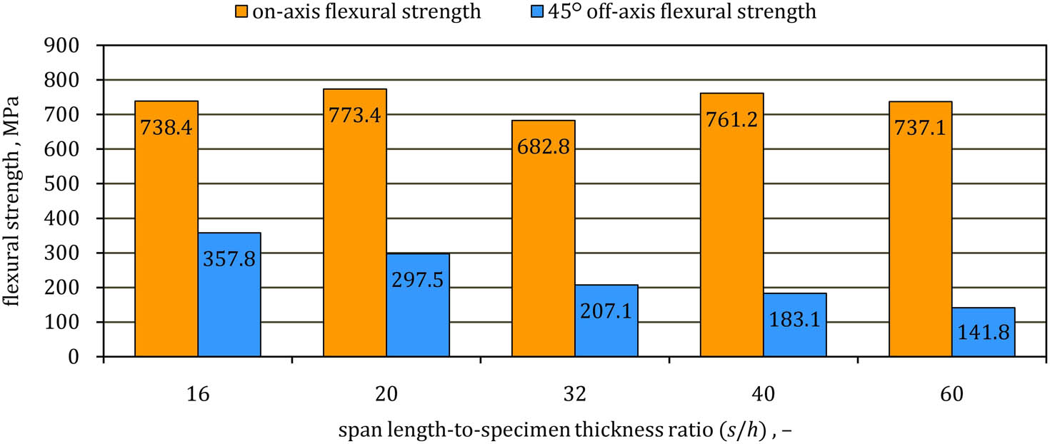
Based on Table 2 and Figure 8, the on-axis flexural modulus increases with increasing (s/h) ratio from 16 to 40, and then it approximately maintains a constant value – this is consistent with the assumptions of the experimental method [21,35]. The true value of the on-axis flexural modulus is equivalent to the maximum value of the flexural modulus at (s/h) ratio of 40 and is equal to 45.36 ± 0.86 GPa.
In turn, the on-axis flexural strength (Figure 9) increases with increasing (s/h) ratio from 16 to 20, and then it significantly decreases at (s/h) ratio of 32. The value of the on-axis flexural strength increases again at (s/h) ratio of 40. However, it should be noted that the value of the on-axis flexural strength at (s/h) ratio of 60 is uncertain because of the sliding behavior of the contact point between CL⊞(60) specimens and supports. The maximum value of the on-axis flexural strength is achieved at (s/h) ratio of 20 and is equal to 773.4 ± 19.4 MPa.
According to Table 2 and Figure 8, the true value of the 45° off-axis flexural modulus cannot be established, because it starts decreasing at (s/h) ratio of 32. The maximum value of the 45° off-axis flexural modulus is achieved at (s/h) ratio of 20 and is equal to 12.35 ± 0.14 GPa.
It is also difficult to obtain the 45° off-axis flexural strength because there is no failure point on the load–deflection curves (Figure 7). Hence, it has been assumed that the 45° off-axis flexural strength for each specimen (Table 2) can be calculated by taking into account the maximum value of force recorded during the test. However, it must be noted that the 45° off-axis flexural strength at (s/h) ratio of 32, 40 and 60 is not accurate due to the large deflection and sliding behavior of the contact point between the specimens and supports. The reliable values of the 45° off-axis flexural strength are obtained only at the (s/h) ratio of 16 and 20. The maximum value of the 45° off-axis flexural modulus is achieved at (s/h) ratio of 16 and is equal to 357.8 ± 10.1 MPa. Based on Table 2 and Figure 8, it is not possible to establish one value of (s/h) ratio for determining the true on-axis and true 45° off-axis flexural moduli of the laminate.
Macroscopic observation of failure mechanisms in the laminate specimens after completion of the three-point flexure tests is shown in Figure 10. Different modes of failure are visible on the front, top and bottom surfaces according to Figure 10a. Failure of CL⊞(16) and CL⊞(20) specimens occurs by a sudden rupture and causes a rapid drop in loading capacity (Figure 6). This failure tends to be initiated at the midspan on the lower surface and propagated through the thickness towards the upper surface (Figure 10b). On the lower surface (bottom view), it takes the form of a thin crack across the width, wherein the front view of the specimens indicates a brittle fracture. The same failure mechanism of bidirectional woven composite specimens was described in ref. [22] − the specimens tested at (s/h) ratio of 20 also exhibited through-thickness cracking with no delamination. This kind of failure occurs when a specimen is dominated by shear, so when it is tested at a short span [25]. During the three-point flexure test with a short span, the horizontal shear stress (in-plane shear stress) and the vertical shear stress (out-of-plane shear stress) have a significant influence on the response of a specimen. Laminates with higher in-plane shear strength are more resistant to delamination. It suggests that the on-axis specimens have higher in-plane shear strength (delamination is not observed) than out-of-plane shear strength (through-thickness brittle fracture is observed).
Failure mode in CL⊞(32), CL⊞(40) and CL⊞(60) specimens is classified as flexural tension failure, which is expected during the three-point flexure test at a higher (s/h) ratio. The failure mechanism progresses gradually with specific cracking sounds, the number of which increases with increasing deflection until complete failure. Visual and macroscopic observations of these specimens after completion of the test also show the presence of delamination cracks (Figure 10c). However, no significant patterns of delamination are observed during the tests. The sudden formation of the large delamination zone in CL⊞(32), CL⊞(40) and CL⊞(60) specimens may be related to the relatively unstable growth of crack and rapid drop in loading capacity.
In the case of the 45° off-axis specimens, despite the large deflection, final failure is not observed during the tests. Visual observation of the specimens after completion of the tests reveals just one type of crack on the upper surface – it applies only to CL⊠(16) and CL⊠(20) specimens (no significant patterns of any cracks are observed in the case of CL⊠(32), CL⊠(40) and CL⊠(60) specimens). Visual observation of the upper surface of CL⊠(16) and CL⊠(20) specimens shows that these cracks form in the matrix along the edges of interlacing weft and warp as illustrated in Figure 10d. Due to the location of the cracks on the upper surface, it can be assumed that the mechanism of the formation of the cracks may be related to compressive stress. However, it is difficult to clearly identify the reason for these cracks, because a transverse deformation of the 45° off-axis specimens is also observed during the test. The transverse deformation of the 45° off-axis specimens is explained in detail in Figure 11. As a result of this deformation, the contact between the 45° off-axis specimen and supports during the loading is just at two points (π1 and π2-plane views) − these specimens, unlike the on-axis specimens, are not in contact with the supports across the width. Smaller contact with the supports, and consequently smaller friction area can also be an additional reason for the sliding behavior of the 45° off-axis specimens. The transverse deformation also causes point contact between the specimens and the loading pin (π3-plane view). An additional feature of the 45° off-axis specimens is the spring-back effect after completion of the test and unloading. Despite the large deflection (even of the value of 10 mm at (s/h) ratio of 20 – Figure 10d), the specimens show relatively little permanent deflection approximately equal to their thickness. Due to all these factors, the analysis of the flexural response of the 45° off-axis specimens is difficult.
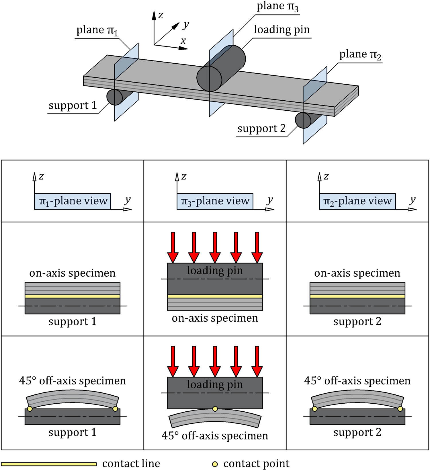
Comparison of transverse deformation of the on-axis and 45° off-axis specimens during the three-point loading.
4 Conclusions
This study aims to examine the flexural properties of bidirectional CL reinforced with eight layers of plain weave carbon fiber fabric under three-point flexure loading conditions. The flexural response of the laminate is tested using on-axis and 45° off-axis rectangular specimens with the lay-up [(0/90)F]8 and [±45 F]8, respectively. In order to obtain more information about the mechanical properties of the laminate, the flexural tests are carried out at five span length-to-specimen thickness ratios (s/h). The key results are outlined along the following lines:
the on-axis flexural modulus is approximately four times higher than the 45° off-axis flexural modulus,
the on-axis flexural modulus increases with increasing (s/h) ratio from 16 to 40, and then it approximately maintains a constant value,
the 45° off-axis flexural modulus reaches the maximum value at (s/h) ratio of 20, and then it gradually decreases with increasing (s/h) ratio,
the maximum values of the on-axis and 45° off-axis flexural moduli are not obtained at the same (s/h) ratio,
the on-axis flexural strength reaches the maximum value at (s/h) ratio of 20,
determination of the 45° off-axis flexural strength is difficult because the 45° off-axis specimens reach large deflection without final failure – there is also sliding behavior of the contact point between the specimens and supports,
the on-axis specimens get damaged in different ways − from a brittle fracture at (s/h) ratio of 16 and 20 to flexural tension failure at (s/h) ratio of 32, 40 and 60,
despite the large deflection, the 45° off-axis specimens show fracture resistance behavior under the three-point flexure loading conditions – after completion of the flexure tests, unloaded specimens show spring-back behavior and small permanent deformation,
the 45° off-axis specimens show a specific deformation in the transverse direction during the three-point flexure loading,
the three-point flexure test with a long support span may be unsuccessful due to the possibility of sliding behavior of the contact point between a specimen and supports.
-
Conflict of interest: The author has no conflict of interest to declare.
References
[1] Rajak DK, Pagar DD, Menezes PL, Linul E. Fiber-reinforced polymer composites: manufacturing, properties, and applications. Polymers. 2019;11(10):1667.10.3390/polym11101667Search in Google Scholar PubMed PubMed Central
[2] Salasinska K, Barczewski M, Aniśko J, Hejna A, Celiński M. Comparative study of the reinforcement type effect on the thermomechanical properties and burning of epoxy-based composites. J Compos Sci. 2021;5(3):89.10.3390/jcs5030089Search in Google Scholar
[3] Ekşi S, Genel K. Comparison of mechanical properties of unidirectional and woven carbon, glass and aramid fiber reinforced epoxy composites. Acta Phys Pol. 2017;132(3–II):879–82.10.12693/APhysPolA.132.879Search in Google Scholar
[4] Meninno C, Chalivendra V. Damage detection in intra-ply glass/carbon laminated composites under Mode-I and Mode-II fracture loadings. Compos B Eng. 2021;218:108924.10.1016/j.compositesb.2021.108924Search in Google Scholar
[5] Khandan R, Noroozi S, Sewell P, Vinney J, Koohgilani M. Optimum design of fibre orientation in composite laminate plates for out-plane stresses. Adv Mater Sci Eng. 2012;2012:232847.10.1155/2012/232847Search in Google Scholar
[6] Kesarwani S. Polymer composites in aviation sector. Int J Eng Res Technol. 2017;6(6):518–25.10.17577/IJERTV6IS060291Search in Google Scholar
[7] Liu D, Tang Y, Cong WL. A review of mechanical drilling for composite laminates. Compos Struct. 2012;94:1265–79.10.1016/j.compstruct.2011.11.024Search in Google Scholar
[8] Balakrishnan VS, Seidlitz H. Potential repair techniques for automotive composites: A review. Compos B Eng. 2018;145:28–38.10.1016/j.compositesb.2018.03.016Search in Google Scholar
[9] Henning F, Kärger L, Dörr D, Schirmaier FJ, Seuffert J, Bernath A. Fast processing and continuous simulation of automotive structural composite components. Compos Sci Technol. 2019;171:261–79.10.1016/j.compscitech.2018.12.007Search in Google Scholar
[10] Afshar A, Alkhader M, Korach CS, Chiang F-P. Effect of long-term exposure to marine environments on the flexural properties of carbon fiber vinylester composites. Compos Struct. 2015;126:72–7.10.1016/j.compstruct.2015.02.008Search in Google Scholar
[11] Gagani AI, Krauklis AE, Sæter E, Vedvik NP, Echtermeyer AT. A novel method for testing and determining ILSS for marine and offshore composites. Compos Struct. 2019;220:431–40.10.1016/j.compstruct.2019.04.040Search in Google Scholar
[12] Bijwe J, Rattan R. Influence of weave of carbon fabric in polyetherimide composites in various wear situations. Wear. 2007;263:984–91.10.1016/j.wear.2006.12.030Search in Google Scholar
[13] Adumitroaie A, Barbero EJ. Beyond plain weave fabrics − II. Mechanical properties. Compos Struct. 2011;93:1449–62.10.1016/j.compstruct.2010.11.016Search in Google Scholar
[14] Akkerman R. Laminate mechanics for balanced woven fabrics. Compos B Eng. 2006;37:108–16.10.1016/j.compositesb.2005.08.004Search in Google Scholar
[15] Hasan KMF, Horváth PG, Alpár T. Potential fabric-reinforced composites: A comprehensive review. J Mater Sci. 2021;56:14381–415.10.1007/s10853-021-06177-6Search in Google Scholar
[16] Inagaki M. New carbons − control of structure and functions. 1st edn. Amsterdam: Elsevier Science; 2000.10.1016/B978-008043713-2/50001-7Search in Google Scholar
[17] Ostapiuk M, Bieniaś J, Surowska B. Analysis of the bending and failure of fiber metal laminates based on glass and carbon fibers. Sci Eng Compos Mater. 2018;25(6):1095–106.10.1515/secm-2017-0180Search in Google Scholar
[18] Hou P, Zhao H, Ma Z, Zhang S, Li J, Dong X, et al. Influence of punch radius on elastic modulus of three-point bending tests. Adv Mech Eng. 2016;8(5):1–8.10.1177/1687814016649116Search in Google Scholar
[19] ASTM International. D7264/D7264M – 21. Standard test method for flexural properties of polymer matrix composite materials. West Conshohocken, PA: ASTM; 2021.Search in Google Scholar
[20] ASTM International. D790 – 17. Standard test methods for flexural properties of unreinforced and reinforced plastics and electrical insulating materials. West Conshohocken, PA: ASTM; 2017.Search in Google Scholar
[21] Carlsson LA, Adams DF, Pipes RB. Experimental characterization of advanced composite materials. 4th edn. Boca Raton: CRC Press; 2014.10.1201/b16618Search in Google Scholar
[22] Kumar MS, Raghavendra K, Venkataswamy MA, Panbarasu K, Ranganath VR. Effect of span length on micromechanics of fracture under flexure load in CFRP composites. Mech Adv Mater Struct. 2018;25(9):756–65.10.1080/15376494.2017.1308584Search in Google Scholar
[23] Mehndiratta A, Bandyopadhyaya S, Kumar V, Kumar D. Experimental investigation of span length for flexural test of fiber reinforced polymer composite laminates. J Mater Res Technol. 2018;7(1):89–95.10.1016/j.jmrt.2017.06.010Search in Google Scholar
[24] Sideridis E, Papadopoulos GA. Short-beam and three-point-bending tests for the study of shear and flexural properties in unidirectional-fiber-reinforced epoxy composites. J Appl Polym Sci. 2004;93:63–74.10.1002/app.20382Search in Google Scholar
[25] Lee T-I, Kim C, Kim MS, Kim T-S. Flexural and tensile moduli of flexible FR4 substrates. Polym Test. 2016;53:70–6.10.1016/j.polymertesting.2016.05.012Search in Google Scholar
[26] Dong C, Davies IJ. Optimal design for the flexural behaviour of glass and carbon fibre reinforced polymer hybrid composites. Mater Des. 2012;37:450–7.10.1016/j.matdes.2012.01.021Search in Google Scholar
[27] Dong C, Sudarisman, Davies IJ. Flexural properties of E glass and TR50S carbon fiber reinforced epoxy hybrid composites. J Mater Eng Perform. 2013;22(1):41–9.10.1007/s11665-012-0247-7Search in Google Scholar
[28] Sudarisman, Davies IJ. Flexural failure of unidirectional hybrid fibre-reinforced polymer (FRP) composites containing different grades of glass fibre. Adv Mat Res. 2008;41-42:357–62.10.4028/www.scientific.net/AMR.41-42.357Search in Google Scholar
[29] Soliman E, Kandil U, Taha MR. Improved strength and toughness of carbon woven fabric composites with functionalized MWCNTs. Materials. 2014;7:4640–57.10.3390/ma7064640Search in Google Scholar
[30] Chamis CC. Analysis of the three-point-bend test for materials with unequal tension and compression properties. NASA TN D-7572. Cleveland: National Aeronautics and Space Administration; 1974.Search in Google Scholar
[31] Ullah H, Harland AR, Silberschmidt VV. Characterisation of mechanical behaviour and damage analysis of 2D woven composites under bending. Compos B Eng. 2015;75:156–66.10.1016/j.compositesb.2015.01.036Search in Google Scholar
[32] Fard MY, Liu Y, Chattopadhyay A. A simplified approach for flexural behavior of epoxy resin materials. J Strain Anal Eng Des. 2012;47(1):18–31.10.1177/0309324711430023Search in Google Scholar
[33] Fiedler B, Hojo M, Ochiai S, Schulte K, Ando M. Failure behavior of an epoxy matrix under different kinds of static loading. Compos Sci Technol. 2001;61(11):1615–24.10.1016/S0266-3538(01)00057-4Search in Google Scholar
[34] Ramírez-Herrera CA, Cruz-Cruz I, Jiménez-Cedeño IH, Martínez-Romero O, Elías-Zúñiga A. Influence of the epoxy resin process parameters on the mechanical properties of produced bidirectional [±45°] carbon/epoxy woven composites. Polymers. 2021;13:1273.10.3390/polym13081273Search in Google Scholar PubMed PubMed Central
[35] Ochelski S. Metody doświadczalne mechaniki kompozytów konstrukcyjnych. Warszawa: Wydawnictwa Naukowo-Techniczne; 2004.Search in Google Scholar
© 2022 Jerzy Marszałek, published by De Gruyter
This work is licensed under the Creative Commons Attribution 4.0 International License.
Articles in the same Issue
- Regular Articles
- Experimental investigations of a novel pressure microfoam preparation device for dust removal
- Influence of hydrothermal aging on the mechanical performance of foam core sandwich panels subjected to low-velocity impact
- Experimental study on surface wrapping strengthening of EPS particles and its concrete performance
- Modification of mechanical properties of Shanghai clayey soil with expanded polystyrene
- A new EPS beads strengthening technology and its influences on axial compressive properties of concrete
- A novel superabsorbent material based on soybean straw: Synthesis and characterization
- Use of line laser scanning thermography for the defect detection and evaluation of composite material
- Research on back analysis of meso-parameters of hydraulic cemented sand and gravel based on Box-Behnken design response surface
- Hot deformation behavior and microstructure of a 0.5 wt% graphene nanoplatelet reinforced aluminum composite
- Analysis of electromagnetic characteristics of the proposed composite four-rail electromagnetic launcher
- Preparation and characterization of a graphene hybridizing polyurethane damping composite
- Effects of layup parameters and interference value on the performance of CFRP–metal interference fit joints
- Vibration and noise reduction of pipelines using shape memory alloy
- Finite element analysis of behavior and ultimate strength of composite column
- Dynamic response of functionally graded plate under harmonic load with variable gradient parameters
- Deformation behavior of rubber composite based on FEA and experimental verification
- Effects of Z-pin on moisture absorption property and damage mode under flexural load for carbon fiber composite
- Design and testing of a smart rubber stave for marine water-lubricated bearings
- Study of carbon nano-modifier of fly ash in cement concrete mixtures of civil engineering
- Analysis of multiple impact tests’ damage to three-dimensional four-directional braided composites
- Theoretical analysis of aluminum honeycomb sandwich panel supported by reinforced concrete wall under low-speed impact load
- Effects of local fiber discontinuity on the fatigue strength parameter at the fiber inclusion corner in fiber-reinforced composites
- Experimental investigation on compressive properties of three-dimensional five-directional braided composites in hygrothermal environment
- Failure process of steel–polypropylene hybrid fiber-reinforced concrete based on numerical simulations
- A simple method for measuring the monofilament diameter of continuous filament yarn with high bending stiffness via synthetic laser imaging
- Span length effect on flexural properties of composite laminate reinforced with a plain weave carbon fiber fabric in a polymer matrix
- Mechanical properties improving and microstructure characterization of inorganic artificial stone binder
- Effect of thermal treatment process on the structure of C/SiO2 composite aerogels
- Mechanical and corrosion resistance analysis of laser cladding layer
- Wear and corrosion mechanisms of Ni–WC coatings modified with different Y2O3 by laser cladding on AISI 4145H steel
- Damage and failure analysis of composite stiffened panels under low-velocity impact and compression after impact with damp-heat aging
- In-situ CT characterization of 2D woven SiCf/SiC composite loading under compression
- Effect of the manufacturing process on the equivalency qualification of glass fiber reinforced polymer
- Study of concrete properties based on crushed stone sand mixture and fiber of fly ash of thermal power plants
- Establishment of wear mechanism distribution diagram of ZTAp-reinforced iron matrix composites
- Calculation method of elastic modulus for carbon fiber-reinforced plastics considering inhomogeneous interphase
- An experimental study on the failure and enhancement mechanism of bolt-strengthening GFRP T-joint subjected to tensile loading
- The viability of cell that encapsulated in calcium alginate hydrogel beads
- Discussion of ceramic bar reinforced TWIP steel composite structure
- A theoretical framework underlying an accelerated testing method and its application to composites under constant strain rates and fatigue loading
- Theoretical analysis of interfacial design and thermal conductivity in graphite flakes/Al composites with various interfacial coatings
- Multiscale heat conduction and fractal oxidation behaviors of needle-punched carbon/carbon composites
- Numerical simulation of composite grid sandwich structure under low-velocity impact
- Wear properties of Al/TiO2 composites fabricated via combined compo-casting and APB process
- Review Articles
- Application of melanin as biological functional material in composite film field
- Review on research progress of cemented sand and gravel dam
- Communication
- Fabrications and microstructure analysis of cobalt-based coatings by an easy-coating and sintering process
- Letter to the Editor
- Investigation on mechanical and conductive behaviors of nano-graphite-based concrete