Mixed-mode I/III fracture toughness of polymer matrix composites toughened with waste particles
-
Mohamad Alsaadi
 ,
Ahmet Erkliğ
,
Ahmet Erkliğ

Abstract
Fracture toughness of particle-filled polymer composite beams with different particle content for varying of crack inclination angles was investigated in mode I and mode III loading conditions. The beams were tested using three-point bending test with crack inclination angles of 30°, 45°, 75°, and 90°. Sewage sludge ash (SSA), fly ash (FA), and silicon carbide (SiC) microparticles were used as toughening fillers with 5, 10, 15, and 20 wt% contents of the total weight of the polymer composites. The scanning electron microscope (SEM) micrographs showed that a good indication was observed for dispersion of FA, SSA, and SiC particles within the polymer matrix. The critical crack tip stress intensity factors KIc (crack angle 90°) and KIIIc, and the critical strain energy release rates GIc and GIIIc were calculated and their results were compared. The mode I and mode III fracture toughness of the particulate polyester composite were improved by addition of particulate fillers. The maximum values of fracture toughness mode I (KIc and GIc) and mode III (KIIIc and GIIIc) were recorded at particle content of 5 wt% polymer composites.
1 Introduction
Industrial applications of polymers have increased and are being continuously developed in various fields such as construction, automotive, marine, and aerospace industries using additive reinforcement. The inclusion of fillers into the polymers may contribute to enhance different mechanical properties like strength and fracture toughness in addition to providing a significant cost reduction of the polymer composite [1], [2], [3], [4], [5], [6], [7], [8], [9], [10], [11], [12], [13], [14], [15], [16], [17]. In addition, the mechanical properties of the polymer-based particulate composites have been affected by particle content and adhesion strength of particle/matrix interface [2], [3], [4], [5]. There are many fillers that can improve the mechanical properties and fracture toughness of composites such as industrial wastes: sewage sludge ash (SSA), fly ash (FA), and rice husk ash or conventional ceramic powders: silicon carbide (SiC), glass, alumina, silica, etc. [6], [7], [8], [9], [10], [11], [12], [13]. The industrial wastes SSA and FA affect the environment hazardously; therefore, recycling of these wastes plays an important role in the reduction of their harmful effects [6], [7], [8], [9]. Generally, the usage of the polymer composite including FA particles has shown positive effects on tensile, flexural, and fracture properties at a certain weight fraction and particle sizes in the range of 26–152 μm [6], [7], [8].
Filler of SSA is produced from wastewater purification operation. A few studies examined the usage of SSA with particle sizes in the range of 1–250 μm and their applications in the construction industry have contributed to improve the mechanical properties [9], [10]. Bhagyashekar and Rao [11] indicated that the inclusion of microscale SiC particles up to a content of 30 wt% within the epoxy resin showed an increase in the tensile and flexural modulus of the composites.
In recent years, several researchers have conducted many experimental studies on the fracture behavior of particle-filled polymer composites of single edge notch bend (SENB) specimens under mode I fracture [12], [13], [14], [15], [16], [17]. Roulin et al. [17] showed that the mode I stress intensity factor of the SiC particles filled polymer composite for SENB specimens increased with the addition of SiC particles. In general, mixed-mode fracture is the most common fracture case related to crack bodies. Hence, various studies have been achieved with the aim of testing mixed-mode fracture toughness I/II [18], [19], [20] and I/III [21], [22], [23], [24], [25], [26]. Avci et al. [26] investigated the effect of varying crack angles for the SENB specimens on the mixed-mode I/III fracture toughness behavior of the polyester resin filled with sand particles and chopped glass fiber. Qinghua and Jianqiao [27] stated that the mechanical interaction between microsize particle and crack tip could give rise to composite toughness. They clarified that this behavior appeared especially in the form of crack tilting (opening and sliding) for mixed-mode I/II or crack twisting (opening and tearing) for mixed-mode I/III.
Based on the literature survey, many of these studies dealt with mode I or mixed-mode fracture toughness I and II and I and III with different particle types. But, to our knowledge, never has been studied the effect of microscale SSA, FA, and SiC particles in the polymer composite on the mixed-mode fracture toughness (I+III). The objective of this article is to study the effects of three particulate fillers on the mixed-mode fracture behavior of particle-filled polymer composites. The effects of industrial wastes FA and conventional particle SiC on the mechanical properties of the polymer composites are well known and have been studied by many researchers. Because of this, the fillers of FA and SiC were used to compare with new industrial waste SSA. The particle weight fractions were 5%, 10%, 15%, and 20% content of the total weight of the polymer composites. The SENB beams were tested with crack inclination angles 30°, 45°, 75°, and 90° using three-point bending (TPB) test. The critical crack tip stress intensity factors (KIc, crack angle 90° and KIIIc), and the critical strain energy release rates (GIc and GIIIc) were determined and results were compared.
2 Specimens preparation and tests
2.1 Materials
A general purpose reaccelerated and unsaturated polyester resin (Polipol 3401-TAB) with a density of 1.105 g/cm3 was supplied by the Poliya Composite Resins and Polymers (Istanbul, Turkey). This resin provides rapid and best cure product with the addition of 2 wt% of methyl-ethyl-ketone-peroxide as a hardener.
Microscale SSA, FA, and SiC fillers were supplied by Şahinbey Belediyesi, Çatalağzı Thermal Power Plant and Esan Company in Gaziantep, Turkey, respectively. The particle size of the fillers was measured approximately as 35 μm for SiC and 1–35 μm for grinded and garbled SSA and FA fillers. The bulk density was measured as 0.72, 1.02, and 1.49 g/cm3 for SSA, FA, and SiC filler, respectively, and their chemical compositions are given in Table 1. All samples were prepared by mixing unsaturated polyester resin at particle contents of 5, 10, 15, and 20 wt% of the total weight of composite specimen.
Chemical compositions of filler materials.
| Filler | Chemical formula/composition (wt%) |
|---|---|
| Sewage sludge ash | P2O5 (23.56), CaO (19.58), SiO2 (16.6), SO3 (8.53), MgO (8.22), Fe2O3 (7.46), Al2O3 (5.73), K2O (4.87), ZnO (2.09), TiO2 (1.08), Cl(0.54), Na2O (0.44), Cr2O3 (0.24), BaO(0.21), CuO(0.19), MnO2 (0.18) |
| Fly ash | SiO2 (57.20), Al2O3 (24.40), Fe2O3 (7.10), K2O (3.37), MgO (2.40), CaO (2.24), Na2O (0.38), SO3 (0.29) |
| Silicon carbide | SiC (100) |
2.2 Specimens preparation
The particulate polyester-matrix composite specimens were produced by pouring the particulate mixture in the mold. The measured quantity of the particle was put in the polyester resin and evenly mixed using a mechanical stirrer with a speed of 750 rpm for 20 min in order to attain a homogeneous mixture. Then, 2 wt% of hardener was added to the mixture for quick setting of composite specimen. The polymer composites were molded and cured at room temperature for 1 day. Then, specimens were post-cured in the room temperature for 2 weeks preparing for mechanical testing.
The specimens were prepared according to the following procedures:
Tensile tests were performed according to the ASTM D 638 standard with dimensions of 165 mm× 13 mm×4 mm for a gauge length of 50 mm.
Fracture tests were performed according to ASTM D 5045 standard with dimensions of 88 mm× 20 mm×10 mm and a/W=0.45, where a and W are crack depth and thickness of the specimen, respectively.
To create notches having 9 mm deep with the angle θ inclined to the beam axis as shown in Figure 1, the SENB specimens were cut by using a 0.6 mm thick cutter. Surgery blade was used to sharpen the notch tips of the specimen with the crack inclination angles of θ=30°, 45°, 75°, and 90° to the beam axis.

Schematics of the geometrical configuration SENB specimen.
2.3 Tensile tests
The tensile tests were performed to measure tensile modulus and Poisson ratio, which are needed to calculate fracture toughness properties. Tensile properties of the dog-bone-shaped particulate polymer composites were determined according to the ASTM D638-10 standard test method using the Shimadzu testing machine AG-X series (Shimadzu Corporation, Kyoto, Japan) and data acquisition card Ni-9237 (National Instruments Corporation, Austin, TX, USA) (Figure 2). During the testing, the crosshead speed was set to 2 mm/min. At least three specimens were tested for each particle content, and average value of the results was calculated.

Tensile test devices.
2.4 Three-point bending tests
Three-point bending tests were conducted on un-notched and SENB specimens with a crosshead speed of 0.5 and 0.2 mm/min, respectively. At least three specimens were tested for each particle content, and the mean value of these tests was calculated. Mode I fracture toughness tests were performed on SENB specimens according to the ASTM D 5045 standard using the Shimadzu AG-X series testing machine in order to evaluate the apparent stress intensity factor Kc. The mixed-mode fracture toughness tests were conducted by using a modified SENB specimen [20], [23], [25]. Hence, the standard SENB specimens related to the mode I conditions were performed at the crack inclination angle 90°. Consequently, when the crack inclination angle θ (Figure 1) was less than 90° under the bending loads, the crack surface was divided into a mode I and mode III. Due to the notch rotation in the mixed-mode conditions, the crack plane would twist, and this is attributed to the effect of mode III components [22]. Therefore, the crack is exposed to mixed-mode conditions and the critical stress intensity factor can be resolved to KIc and KIIIc.
3 Experimental results and discussion
3.1 Morphology
The morphology of the particle-filled polyester-matrix composites was investigated using a scanning electron microscope (SEM) (JEOL JSM-6390 lv, Gaziantep University, Gaziantep, Turkey), and their micrographs are given in Table 2. It can be noticed in the SEM micrographs (Table 2) that the well distribution of FA, SSA, and SiC particles occurred within the polymer resin. However, when the content of FA, SSA, and SiC particles within polyester composites was above 10 wt%, the particle agglomeration was increased resulting in a larger size of the particle, thus causing weakness in adhesion strength between the particle and matrix. [4], [16]. Therefore, for the FA, SSA, and SiC particle content of 20 wt%, the diameter of large particles reached about 41, 71, and 101 μm, respectively.
SEM micrographs of composite samples at various content of filler (images are at a magnification of 230×).

3.2 Tensile properties of the particulate polymer composite
Table 3 presents the tensile properties of the composites for various particle contents. In spite of the tensile tests presenting a nonlinear response of the elastic plastic curves of the studied particulate composite (Figure 3), all the fracture surfaces of the samples were flat without any nicking or shear edges. Accordingly, the samples failed in a brittle manner when they were tested. Moreover, there was no effective permanent decrease in samples’ cross-sectional area. Therefore, the samples of particulate composite exhibit a quasi-brittle behavior.
Tensile properties of the particulate polymer composites.
| Material type | Filler content (wt%) | Tensile strength (MPa) | Tensile modulus (MPa) | Poisson ratio |
|---|---|---|---|---|
| Neat resin | 0 | 48.1 (±1.31) | 2075 (±56) | 0.365 |
| SSA | 5 | 50.2 (±1.06) | 2197 (±59) | 0.354 |
| 10 | 47.2 (±0.65) | 2320 (±65) | 0.337 | |
| 15 | 42.3 (±2.37) | 2601 (±79) | 0.326 | |
| 20 | 40.6 (±1.92) | 2876 (±99) | 0.311 | |
| FA | 5 | 51.9 (±1.71) | 2441 (±81) | 0.340 |
| 10 | 47.5 (±2.58) | 2623 (±74) | 0.315 | |
| 15 | 43.9 (±1.49) | 2914 (±68) | 0.310 | |
| 20 | 41.8 (±2.18) | 3340 (±82) | 0.302 | |
| SiC | 5 | 52.0 (±2.05) | 2516 (±83) | 0.363 |
| 10 | 49.0 (±1.58) | 2646 (±58) | 0.348 | |
| 15 | 47.4 (±1.21) | 3050 (±71) | 0.330 | |
| 20 | 42.2 (±2.52) | 3532 (±95) | 0.324 |

Tensile stress-strain responses at particle contents of 5 and 20 wt%.
It is observed that for all the specimens of the particulate composites, the tensile strength increased up to 5 wt% content of FA, SSA, and SiC, then decreased because of particle agglomeration phenomenon. In addition, tensile strength as the largest stress value reached final value at specimen failure. As shown in the elastic part of stress-strain curves and corresponding data in Table 3, the tensile modulus of composites increases with increasing particle weight content due to higher stiffness of inorganic particles. It is clear that the Poisson ratio values decrease with increasing particle content.
3.3 Three-point bending test of un-notched specimens
The fracture load values of TPB test for un-notched specimens are presented in Table 4, and load-displacement curves are shown in Figure 4. The highest improvement of fracture load was at SSA, FA, and SiC content of 5 wt%, and then followed the trend of decreasing. Hence, the maximum fracture loads for SSA, FA, and SiC composites were 3272, 3163, and 3046 N with a maximum increment of 7.7%, 4.1%, and 0.2%, respectively, compared with that of unfilled composite.
Fracture loads of TPB test for un-notched specimens.
| Composite type/content | Fracture load (N) | ||||
|---|---|---|---|---|---|
| Unfilled | 5 wt% | 10 wt% | 15 wt% | 20 wt% | |
| SSA | 3039 (±62) | 3163 (±43) | 2968 (±52) | 2827 (±55) | 2673 (±85) |
| FA | 3039 (±62) | 3273 (±58) | 3059 (±115) | 2868 (±106) | 2747 (±61) |
| SiC | 3039 (±62) | 3046 (±57) | 2857 (±42) | 2640 (±43) | 2420 (±54) |

Load-displacement curves for un-notched specimens at particle content of 5 and 20 wt%.
3.4 Three-point bending test of SENB specimens
The fracture load of SENB specimens reached its maximum value at SSA, FA, and SiC content of 5 wt%, for θ=90° (Table 5), the same behavior was observed when the crack inclination angle was decreased. This behavior was attributed to the effect of particle agglomeration. Furthermore, for high particle content the large particles caused low interfacial adhesion such that the particles could not pin the crack front and offered little resistance [4], [16], [28].
Fracture loads of TPB test for SENB specimens.
| Composite type | Notch angle, θ (degree) | Fracture load (N) | ||||
|---|---|---|---|---|---|---|
| Unfilled | 5 wt% | 10 wt% | 15 wt% | 20 wt% | ||
| SSA | 90o | 237.7 (±7.3) | 256.3 (±10.7) | 243.8 (±4.5) | 232.0 (±10.2) | 213.6 (±6.3) |
| 75o | 251.9 (±11.1) | 270.3 (±7.5) | 260.5 (±9.0) | 243.4 (±9.4) | 221.8 (±4.2) | |
| 45o | 272.5 (±5.8) | 295.4 (±9.2) | 282.9 (±10.3) | 268.6 (±12.7) | 238.6 (±8.1) | |
| 30o | 315.3 (±6.9) | 348.7 (±5.7) | 341.8 (±6.5) | 317.8 (±7.9) | 274.9 (±9.4) | |
| FA | 90o | 237.7 (±6.5) | 268.6 (±10.8) | 251.2 (±6.7) | 248.8 (±2.5) | 236.3 (±5.9) |
| 75o | 251.9 (±5.4) | 284.1 (±12.1) | 268.5 (±8.3) | 250.1 (±4.1) | 233.0 (±3.4) | |
| 45o | 272.5 (±10.1) | 319.3 (±8.7) | 297.8 (±5.5) | 283.5 (±5.5) | 269.7 (±8.5) | |
| 30o | 315.3 (±8.9) | 332.9 (±4.5) | 323.94 (±7.5) | 306.5 (±9.8) | 287.4 (±11.2) | |
| SiC | 90o | 237.7 (±7.4) | 247.0 (±5.8) | 231.9 (±11.1) | 208.7 (±5.9) | 176.3 (±10.3) |
| 75o | 251.9 (±5.8) | 260.2 (±9.5) | 236.8 (±12.8) | 217.1 (±7.2) | 190.7 (±7.5) | |
| 45o | 272.5 (±8.9) | 281.0 (±6.4) | 263.8 (±7.6) | 229.6 (±10.3) | 209.4 (±8.2) | |
| 30o | 315.3 (±8.5) | 325.4 (±7.2) | 304.7 (±9.5) | 287.2 (±13.1) | 255.8 (±12.4) | |
It is obviously seen that in Table 5 and Figure 5, the magnitude of the load for θ=30° is higher than the other inclination angles for all filler types. This failure was seen in all weight fractions of particulate composite specimens with the crack inclination of θ=30°. It is also clear in Figure 5 that the load-displacement curves of unfilled and particulate filled polyester seem to follow linear behavior up to fracture load.

Load-displacement curves for SENB specimens having different crack inclination angles at content of 5 wt% (A) SSA, (B) FA, and (C) SiC.
3.5 Crack paths
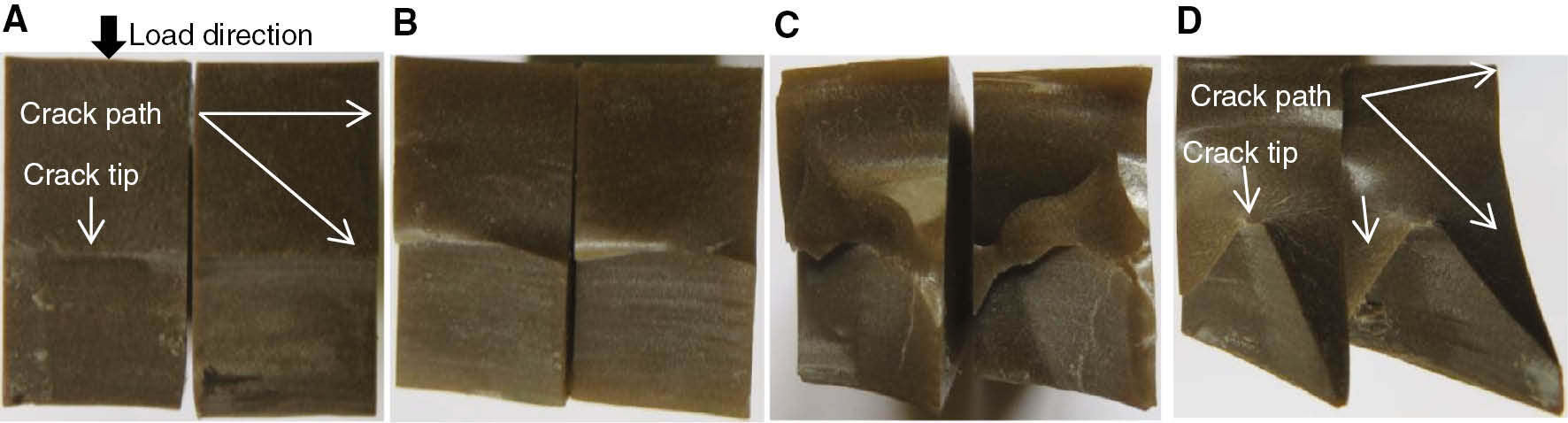
The fracture surfaces of the SSA composite specimens for the content of 5 wt% with different crack angles are shown in Figure 6. In general, the crack forms continuously along the preliminary crack when θ=90o. Hence, for θ< 90o, not only crack propagated within an angle according to the preliminary crack, but also the crack twisted along the direction of propagation. The same behavior was observed by several researchers [21], [24] who showed that crack would propagate by the twisted path for θ<90o. The bright crack surface (Figure 7A) showed the brittle behavior of the mode I fracture. When crack inclination angle was less than 90o, crack propagation was turned from a nearly straight path of the crack (Figure 7A) to curved-path crack propagation (Figure 7B–D). Similar behavior was observed for various particle contents of the three particulate polyester composite systems.

Crack kink angles of SENB specimens at SSA content of 5 wt% for: (A) mode I θ=90°, (B) mixed-mode θ=75°, (C) mixed-mode θ=45°, (D) mixed-mode θ=30°.
Fracture surfaces of SENB specimens at SSA content of 15 wt% for: (A) mode I θ=90°, (B) mixed-mode θ=75°, (C) mixed-mode θ=45°, (D) mixed-mode θ=30°.
4 Determination of critical stress intensity factors
The stress intensity factors for SENB samples of linear elastic fracture mechanics (LEFM) were examined by some researchers [23], [24], [25], [26], [29], [30]. The critical stress intensity factor for mode I can be calculated by using initial notch depth method from the following equations:
where P is the fracture load for crack propagation, B is the specimen width, and s is the length of the span.
There is no standard method available to determine the critical stress intensity factor for mixed-mode I and III. However, for an inclined crack Pook [23], Manoharan and Lewandowski [25], and Avci et al. [26] indicated that the apparent stress intensity factor KAcan be calculated by equation (1) for the mixed-mode I and III. The resulting values of KIcand KIIIcwere obtained by substitution KAinto equations (3) and (4) as follows:
and
The critical stress intensity factors KIcand KIIIcwere calculated from equations (1), (3) and (4), as:
and
The variation of the stress intensity factors (KIc and KIIIc) with the crack inclination angle and particle content is shown in Figure 8. When the crack inclination angle changed from 0º to 90º, the KIc increased to reach the highest values at θ=90º as 1.67, 1.73, and 1.56 MPa√m at particle content 5 wt% of SSA, FA, and SiC composites, respectively. In contrary, KIIIcreached maximum values at θ=30º, while these values decreased with inclusion of mode I loading condition to the system. As expected, at θ=90º KIIIcvalues reached zero. KIcand KIIIc values were equal at the crack inclination of 45º due to equal loading condition.

Mode I and mode III critical stress intensity factors of (A) SSA, (B) FA, and (C) SiC filled polyester composites.
The increment in KIIIc values was attributed to the increase in the crack surface area due to the change in crack inclination angle as the crack propagates (fracture plane at an angle to the pre-crack), leading to an increase in the fracture toughness.
It was noticed that the studied particulate polymer composites exhibited brittle nature of composites; as even under a mixed-mode fracture, the fracture of these composites had a tendency to pure mode I. The results indicated clearly the effect of this phenomenon, as even at lower crack angles; the values of KIcbecame significant and showed slight difference with KIIIc.
The KIc and KIIIcvalues of the particulate polymer composites were also affected by the particle content and filler type. Hence, the KIc and KIIIc of the particulate composites start to decrease with SSA, FA, and SiC content above 5 wt%. This behavior was attributed to particles agglomeration that could have occurred and caused stress concentration areas and eventually weakened the interfacial adhesion between the matrix and particle. Therefore, the good interfacial adhesion lead to particles can pin the crack front and offer more crack growth resistance causing enhancement in the fracture toughness of the particulate polymer composite [16], [28].
5 Determination of critical strain energy release rate
In the initial notch depth method, as the particulate polymer composite is assumed to exhibit quasi-brittle behavior during SENB tests, LEFM can be implemented to calculate the KIcand KIIIcvalues, which can be used to calculate GIcand GIIIcaccording to equations (7) and (8), respectively:
and
where ν and E are Poisson ratio and tensile modulus of the composite, respectively. The strain energy release rate matches J-integral for linear elastic materials.
In general, the GIcand GIIIccurves behavior (Figure 9) followed the same behavior as the KIcand KIIIc curves. The GIc values increased as the crack inclination angle increased from θ=30° to θ=90°, while the GIIIc values decreased. However, Figure 9A shows that for the SSA filler, the GIIIc value momentarily increases from θ=30° to θ=45° and then continue to decrease up to θ=90°. The highest GIc and GIIIc values were observed at FA content of 5 wt% with an increment of 13.0% and 27.3% (at θ=75o) compared to bulk polyester, respectively. While the lowest GIc and GIIIc values were recorded at SiC content of 20 wt% with a decrement of 66.3% and 68.9% (at θ=75o) lower than bulk polyester, respectively. For SSA-filled composites, the maximum GIc and GIIIc values were obtained at content of 5 wt% with an increment of 2.1% (at θ=45o) and 4.5% (at θ=75o) higher than bulk polyester, respectively.

Mode I and mode III critical energy release rate of (A) SSA, (B) FA, and (C) SiC filled polyester composites.
6 Conclusion
The effects of industrial wastes, SSA and FA, and conventional ceramic powder, SiC with variations of particle contents on tensile strength and fracture toughness of particulate polyester composites were examined. The results showed that the composite strength and mixed-mode I and III fracture toughness were affected by the addition of particles, and that was attributed to the relation between the transferred stress between matrix and particle and the particle/matrix interfacial adhesion strength. The SEM micrographs results indicated good dispersion of SSA, FA, and SiC particles within the polymer matrix.
The mode I fracture toughness, KIc, values increased when the crack angle changed from 30o to 90o as the mode III fracture toughness, KIIIc, values decreased. For SENB specimens, the highest values of KIcand KIIIcwere obtained at FA content of 5 wt%, with an increment of 17.1% (at θ=45o) compared to bulk polyester. While the minimum KIcand KIIIc values were obtained at SiC content of 20 wt%, with a decrement of 25.2% and 24.1% (at θ=75o) less than bulk polyester, respectively. For SSA-filled composites, the highest improvement in KIcand KIIIcvalues for SENB specimens were obtained at 5 wt% content, with a maximum increment of 8.4% (at θ=45o) higher than bulk polyester.
The variations of GIcand GIIIcgraphs follow the same behavior of the KIcand KIIIc curves. The values of fracture toughness were consistent. The decreasing of critical strain energy release rate resulted from the high brittleness of composites at high particle content.
As a result, SSA and FA waste particles can be used as fillers for polymer due to good bonding between polymer matrix and these particles that significantly affected the tensile strength and fracture toughness values of the studied composites. This mechanism indicated the chemical compatibility of the SSA- and FA-filled polymer composites system.
References
[1] Wang M, Berry C, Braden M, Bonfield W. J. Mater. Sci. Mater. Med. 1998, 9, 621–624.10.1023/A:1008975323486Search in Google Scholar
[2] Spanoudakis J, Young RJ. J. Mater. Sci.1984, 19, 473–486.10.1007/BF02403234Search in Google Scholar
[3] Rothon R. Particulate-filled polymer composites, 2nd ed., John Wiley & Sons: New York, 1995.Search in Google Scholar
[4] Fu SY, Feng XQ, Lauke B, Lauke B, Mai YW. Composites Part B 2008, 39, 933–961.10.1016/j.compositesb.2008.01.002Search in Google Scholar
[5] Wong K, Yousif B, Low K, Ng Y, Tan SL. J. Strain Anal. Engng Design 2010, 45, 67–79.10.1243/03093247JSA553Search in Google Scholar
[6] Sengupta S, Pal K, Ray D, Mukhopadhyay A. Composites Part B 2011, 42,1834–1839.10.1016/j.compositesb.2011.06.021Search in Google Scholar
[7] Patnaik A, Satapathy A, Mahapatra SS, Dash RR. J. Reinf. Plast. Compos. 2008, 28, 1305–1320.10.1177/0731684407086589Search in Google Scholar
[8] Igarza E, Pardo SG, Abad MJ, Cano J, Galante MJ, Pettarin V, Bernal C. Mater. Design 2014, 55, 85–92.10.1016/j.matdes.2013.09.055Search in Google Scholar
[9] Smol M, Kulczycka J, Henclik A, Gorazda K, Wzorek Z. J. Cleaner Prod. 2015, 95, 45–54.10.1016/j.jclepro.2015.02.051Search in Google Scholar
[10] Garcés P, Carrion MP, Alcocel EG, Paya J, Monzó C, Borrachero MV. Waste Manage. 2008, 28, 2495–2502.10.1016/j.wasman.2008.02.019Search in Google Scholar PubMed
[11] Bhagyashekar MS, Rao RM. J. Reinf. Plast. Compos. 2008, 29, 30–44.10.1177/0731684408095034Search in Google Scholar
[12] Yao XF, Xiong TC, Xu W, Yeh HY. Appl. Compos. Mater. 2006, 13, 407–420.10.1007/s10443-006-9026-7Search in Google Scholar
[13] Kitey R, Tippur H. Acta Materialia 2005, 53, 1153–1165.10.1016/j.actamat.2004.11.012Search in Google Scholar
[14] Jajam K,Tippur H. Composites Part B 2012, 43, 3467–3481.10.1016/j.compositesb.2012.01.042Search in Google Scholar
[15] Adachi T, Osaki M, Araki W, Kwon SC. Acta Mater. 2008, 56, 2101–2109.10.1016/j.actamat.2008.01.002Search in Google Scholar
[16] McGrath L, Parnas R, King S, Schroeder JL. Polymer 2008, 49, 999–1014.10.1016/j.polymer.2007.12.014Search in Google Scholar
[17] Roulin A, Cantwell W, Kausch H. Polym. Compos.1987, 8, 314–323.10.1002/pc.750080506Search in Google Scholar
[18] Zappalorto M, Salviato M, Quaresimin M. Latin Am. J. Solids Struct. 2014, 11, 330–334.10.1590/S1679-78252014000200011Search in Google Scholar
[19] Chao YJ, Liu S. Int. J. Fracture 1997, 87, 201–223.10.1023/A:1007499309587Search in Google Scholar
[20] Manoharan M, Hirth J, Rosenfield AR. Scr. Mater. 1989, 23, 763–766.10.1016/0036-9748(89)90527-9Search in Google Scholar
[21] Lazarus V, Leblond JB, Mouchrif SE. J. Mech. Phys. Solids 2001, 49, 1421–1443.10.1016/S0022-5096(01)00008-4Search in Google Scholar
[22] Cambonie T, Lazarus V. Proc. Mater. Sci. 2014, 3, 1816–1821.10.1016/j.mspro.2014.06.293Search in Google Scholar
[23] Pook L. Eng. Fract. Mech. 1971, 3, 205–218.10.1016/0013-7944(71)90032-4Search in Google Scholar
[24] Moghadam B, Taheri F. J. Strain Anal. Engng Design 2013, 4, 1–13.Search in Google Scholar
[25] Manoharan M, Lewandowski J. J. Compos. Mater. 1991, 2, 831–841.10.1177/002199839102500703Search in Google Scholar
[26] Avci A, Akdemir A, Arikan H. Cement Concrete Res. 2005, 35, 243–247.10.1016/j.cemconres.2004.07.003Search in Google Scholar
[27] Qinghua Q, Jianqiao Y. Toughening Mechanisms in Composite Materials, 1st ed., Woodhead Publishing: UK, 2015.10.1016/B978-1-78242-279-2.00001-9Search in Google Scholar
[28] Low LF, Abu Bakar A. J. Appl. Polym. Sci. 2012, 123, 3064–3071.10.1002/app.34888Search in Google Scholar
[29] Tada H, Paris P, Irwin G. The Stress Analysis of Cracks Handbook, 3rd ed., Del. Research: Hellertown, PA, 2000.10.1115/1.801535Search in Google Scholar
[30] Anderson T. Fracture Mechanics Fundamentals and Application, 3rd ed., Taylor & Francis: New York, 2005.10.1201/9781420058215Search in Google Scholar
©2018 Walter de Gruyter GmbH, Berlin/Boston
This article is distributed under the terms of the Creative Commons Attribution Non-Commercial License, which permits unrestricted non-commercial use, distribution, and reproduction in any medium, provided the original work is properly cited.
Articles in the same Issue
- Frontmatter
- Review
- Research review of diversified reinforcement on aluminum metal matrix composites: fabrication processes and mechanical characterization
- Original articles
- On the mechanisms of modal damping in FRP/honeycomb sandwich panels
- Innovative experimental and finite element assessments of the performance of CFRP-retrofitted RC beams under fatigue loading
- Mixed-mode I/III fracture toughness of polymer matrix composites toughened with waste particles
- A novel analytical curved beam model for predicting elastic properties of 3D eight-harness satin weave composites
- Microwave absorption and mechanical properties of double-layer cement-based composites containing different replacement levels of fly ash
- Electrical and rheological properties of carbon black and carbon fiber filled low-density polyethylene/ethylene vinyl acetate composites
- Effect of neutron irradiation on neat epoxy resin stability in shielding applications
- Study on the relation between microstructural change and compressive creep stress of a PBX substitute material
- Chemical synthesis and densification of a novel Ag/Cr2O3-AgCrO2 nanocomposite powder
- Reinforcing polypropylene with calcium carbonate of different morphologies and polymorphs
- Fabrication, mechanical, thermal, and electrical characterization of epoxy/silica composites for high-voltage insulation
- Synergy of cashew nut shell filler on tribological behaviors of natural-fiber-reinforced epoxy composite
- Fabrication and Failure Prediction of Carbon-alum solid composite electrolyte based humidity sensor using ANN
- Investigation of three-body wear of dental materials under different chewing cycles
- Structural and physico-mechanical characterization of closed-cell aluminum foams with different zinc additions
- Mechanical performance of polyester pin-reinforced foam filled honeycomb sandwich panels
- Effect of chemical treatment on thermal properties of hair fiber-based reinforcement of HF/HDPE composites
- Indium doping in sol-gel synthesis of In-Sm co-doped xIn-0.05%Sm-TiO2 composite photocatalyst
- Effect of the meso-structure on the strain concentration of carbon-carbon composites with drilling hole