Automated profile preforming for structural components
-
 ,
,

Abstract
The work presented in this paper addresses various techniques for automated preforming of profiles for structural components made from fiber-reinforced polymer composites. After reviewing the existing preforming techniques, a quantitative comparison with respect to two different application scenarios is presented. The technology comparison is conducted individually for the two application scenarios by means of a weighted decision matrix approach incorporating a list of technical and economic criteria. The preforming costs are derived by means of a bottom-up cost estimation model and are incorporated in the technology comparison.
1 Introduction
Components made from fiber-reinforced polymer composites (FRPC) are of growing importance due to their superior mechanical properties, particularly the high strength-to-weight ratio, and are essential for various industrial sectors, such as aerospace, automotive, energy, or sports industries [1–3]. However, manufacturing of FRPC components is still widely dominated by manual working steps, limiting their chances for applications with high volume production [4]. Considering the family of liquid composite molding (LCM) techniques, the preforming chain is the most crucial part when it comes to high production rates [5–7]. Thus, automated preforming techniques are presently of particular interest [8, 9]. For geometrically simple, i.e. rather flat or slightly curved, large-scale components, such as the skin of a stringer-stiffened airplane wing panel, the required preform can be efficiently manufactured through automated dry fiber placement (AFP). However, automated manufacturing of the geometrically rather small sized and complex stringer preforms is a more challenging task.
The work at hand is based on a short magazine article recently published by the authors [10] and addresses techniques for automated profile preforming, where the following set of requirements on the manufacturing technique needs to be fulfilled:
flexibility in terms of cross-sectional geometry, typically T-, Z-, L-, J-, I-, or C-shaped profiles,
ability to realize a significant portion of off-axis reinforcement, i.e. orientation of the reinforcing fibers transverse to the major dimension of the profile,
flexibility in terms of the number of layers of reinforcing material as well as the architecture of the reinforcing material used to set up the preform,
precompaction of the preform in order to establish:
inherent preform stability,
minimum preform porosity, and thus
high fiber volume fraction
at an early stage of the manufacturing process and
direct realization of near-net-shape preforms, i.e. minimum (manual) reworking.
Moreover, a set of economic requirements are considered:
minimum process preparation effort and manufacturing facility setup time,
high productivity, i.e. a high degree of material throughput related to machine and labor time,
minimum material waste,
high processing speed, and
low manufacturing costs.
2 Automated profile preforming technologies
In the following subsections, a number of technologies for automated profile preforming are described together with their major technical properties.
2.1 Automated dry fiber placement
AFP is characterized by a processing head automatically guided over a tool surface depositing a specific number of dry fiber tows in parallel [11]. For that purpose, a binder material, which is finely dispersed among the fibers, is thermally activated in order to provide the required tack of the material on the substrate. More precisely, the fibers and the binder material are heated in an area close to the nip point of the processing head at first and subsequently compacted through a consolidation roller at the nip point. Various heating systems exist for AFP preforming purposes, such as IR radiant, ultrasonic, microwave, or laser heating. Asareh et al. [12] studied the impact of heating parameters, predominantly in terms of activation temperature, as well as compaction pressure on the mechanical properties of preforms for double-lap shear specimen. Belhaj et al. [13] investigated the influence of layup patterns on preform permeability as well as mechanical properties by variation of the distance between parallel layup paths, thus studying the effect of gaps and overlaps.
In addition to the processing head, a positioning system is required for the AFP process. This can either be addressed by a gantry system with a sufficiently large number of linear axes or an anthropomorphic robot. The latter can – depending on the component dimensions, the operating range of the robot, as well as the required depositing accuracy – optionally be mounted on an additional linear axis for motions of the robot along the length of the component [14].
At present, there are several companies known to offer commercial AFP systems, such as: Automated Dynamics (www.mag-ias.com), MAG Composite Technologies (www.mag-ias.com), MTorres (www.mtorres.es), ElectroImpact (www.electroimpact.com), Coriolis Composites (www.coriolis-composites.com), or Compositence (www.compositence.de). See Figure 1 for a processing head in action, guided by means of a six-axis anthropomorphic robot.

Six-axis anthropomorphic robot guiding an AFP processing head over a curved tool surface. Source: www.coriolis-composites.com
There are various strategies for applying AFP systems to automated profile preforming, which are outlined in the following subsections.
2.1.1 Direct AFP layup
The AFP system can be implemented for the direct layup of fiber tows on dedicated preform tools along pre-specified layup paths as shown in Figure 2. As a result, this additive preform manufacturing approach provides a high level of flexibility considering mid- or large-scale components showing rather low geometric complexity. Addressing profile preforming with a significant portion of fiber reinforcement along the off-axis directions forces the AFP system to deposit the fiber tows along a high number of rather short paths, which makes this layup strategy particularly inefficient [15].
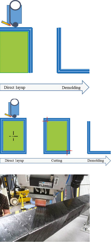
Schematic of direct AFP layup of an L-shaped preform (top) and a square-type bar preform as an initial shape for L- or C-shaped profile preforms (center). Manufacturing close-up of direct AFP preforming (bottom). Source: Airbus Group Innovations.
However, certain profile geometries allow for an improved preforming efficiency by combining multiple preforms into common layup geometry. For example, C- or L-shaped profile preforms can be obtained from rectangular layup geometry as indicated in Figure 2 (center). Following the motion principle of filament winding, the rectangular preform cross-section can be processed more efficiently than the singular profile preforms in terms of the layup paths as depicted in Figure 2 (bottom). However, additional cutting is required, and a higher amount of material waste occurs.
2.1.2 Flat AFP layup, cutting, and draping
In order to overcome the drawback of the direct AFP layup strategy, a three-step procedure can be contemplated, which consists of:
automated layup of a flat preform by means of AFP,
cutting of the preform to sections of required dimensions, and
draping of the preform sections onto a dedicated tool in order to obtain the final preform.
See Figure 3 (left) for a schematic visualization of this strategy. Figure 3 (right) shows a picture of a large-scale manufacturing facility for flat AFP layup following this concept, with an anthropomorphic robot mounted on an additional linear axis for motions of the robot along the length of the component. Although this approach is beneficial over the direct layup approach in terms of the AFP layup paths, the overall procedure is more complex as additional cutting and draping systems are required.

Schematic of flat AFP layup (left) and anthropomorphic robot mounted on an additional linear axis with an AFP head for flat preform layup (right). Source: www.electroimpact.com
2.1.3 Selective flat AFP layup and draping
The need for an additional cutting system mentioned in the previous approach can be avoided by selective layup of flat preform sections as shown in the scheme of Figure 4 (left).

Schematic of selective flat AFP layup of multiple flat preform shapes (left) and manufacturing close-up (right).
Source: www.electroimpact.com
The AFP system can again be utilized more efficiently compared to the direct AFP layup strategy described in Section 2.1.1 as the fiber tows are deposited in rather long layup paths, even for the reinforcements along the profile off-axis directions. Additionally, multiple preforms are directly manufactured in parallel when the individual fiber tows are automatically cut during the layup process as shown in Figure 4 (right). This approach avoids the cutting unit required for the layup strategy in the previous section. However, draping of the preform onto dedicated tools is still required in order to obtain the final profile preform.
2.2 Preform braiding
Profile preforms can be directly manufactured by means of automated braiding technologies [11, 16, 17]. Braiding is recognized as a technique for fabricating near-net-shape preforms, and the technology has reached a high level of automation today. Braided preforms are well suited for complex preform shapes due to outstanding drapability properties.
Conventional (maypole) braiding uses two sets of spool carriers, which are rotating on a circular track around a central axis [18]. The number of spool carriers is chosen in order to meet the desired density of the fiber rovings in the braiding [19]. One set of the carriers, the warp carriers, circulate in counter-clockwise direction, while the weft carriers move in clockwise direction. Horn gears with slots for guiding the carriers allow for superimposing a sinusoidal motion of the spools along the circular track around the braiding axis. As a result, the fiber rovings leaving the spools are interlacing and continuously form the tubular braiding structure. By guiding a mandrel through the central opening of the braiding facility, the fiber rovings are directly deposited on the mandrel surface. The braiding angle, i.e. the angle of the fiber rovings with respect to the braiding axis, is a result of the speed of the rotating horn-gear motion with respect to the speed of axial mandrel motion.
Actually, the resultant braiding is a three-dimensional reinforcing structure, however, the individual fiber bundles are interlacing within a common plane. This is the reason for the term “2D braiding” used for this kind of technology. In the case of 3D braiding, the carrier platform consists of multiple concentric rows or a regular grid of horn gears [19]. The spool carriers move along pre-specified paths over these rows of horn gears. As a result, the fiber rovings leaving the spools are interlacing such that a truly three-dimensional reinforcing structure is obtained [18].
2.2.1 2D braiding
The 2D braiding technology has been addressed for profile preform manufacturing in the past [20, 21] but involves some major drawbacks:
in braidings, the fiber tows shows permanent undulations, thus, losing a significant portion of their mechanical properties,
significant reinforcement transverse to the profile axis cannot be sufficiently fulfilled due to limitations in the achievable braiding angle (typically ranging from 10° to 85°, as, e.g. stated by Potluri et al. [18]),
the braiding technique is limited in terms of directly covering certain cross-sectional profile shapes, particularly concave-shaped profile preforms – however, these can be formed out of circular braidings in a subsequent processing step as outlined by Uozumi et al. [22], and
laborious mounting of roving spools on the braiding machines combined with low spool capacity.
Braided preforms initially consist of single layers of braided fiber rovings. In order to create a multi-layer preform, the braiding process needs to be repeated while reversing the axial mandrel motion after each layer. This strategy is the most common approach and referred to as over-braiding [16].
2.2.2 2D braiding, winding and UD tape integration
Overcoming some of the major disadvantages of 2D braiding, a highly complex modification of the braiding technique has been developed by Airbus Group Innovations (www.airbusgroup.com) and SGL Kümpers (www.sgl-kuempers.com), called the Braided Frames (BraF) process [23]. There, the actual braiding is combined with 90° winding layers as well as UD reinforcement tapes (see Figure 5, top-to-bottom) in a fully automated process to continuously manufacture curved frame preforms at a speed of up to 1 m/min.
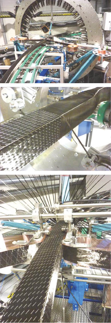
Processing steps of BraF, a braiding process (top) combined with winding of 90° layers (center) and UD tape integration (bottom). Source: Airbus Group Innovations.
The braiding consists of a combination of carbon fiber rovings and auxiliary thermoplastic yarns, a product from EMS-Griltech (www.emsgriltech.com) termed “Grilon® fusible bonding yarn.” These auxiliary yarns act as supports for the reinforcement rovings during the braiding process as well as a binder material in a subsequent preform fixation step. As a result, the crimp is eliminated, and in the final preform, the carbon fiber rovings show a lower amount of undulation compared to conventional 2D braidings. Reinforcements along the profile circumference direction can be added through dry fiber winding, whereas additional reinforcement in the profile axial direction can be realized by integration of UD tape material, which is attached to the preform through over-braiding with a subsequent braiding layer.
Variations of profile curvature as well as profile height can be realized with the BraF process. However, depending on the desired final cross-sectional geometry, further offline processing steps are required such as preform fixation through thermal binder activation or cutting. These requirements disadvantageously influence the overall efficiency of this preforming technology.
2.2.3 3D braiding
3D braidings are manufactured by braiding multiple fiber rovings, which are three-dimensionally oriented and continuously intertwined to create the near-net-shape preform geometry [16, 24]. Polymer composites involving 3D braidings indicate superior mechanical properties in through-thickness direction. However, manufacturing of 3D braidings is considerably slower than processing of conventional 2D braidings because of the high level of complexity of the braiding facility, particularly in terms of the spool carrier track configuration [22]. Varying the cross-sectional geometry of 3D braidings requires laborious rearrangement of the overall track configuration, a task that contributes significantly to the overall production costs. Figure 6 shows a picture of a 3D braiding facility from Herzog Maschinenfabrik GmbH (www.herzog-online.com) operated at Institut für Textiltechnik at RWTH Aachen.

3D braiding facility from Herzog Maschinenfabrik GmbH with a rectangular grid of horn gears. Source: RWTH Aachen.
2.3 Continuous profile preforming
The basic idea of continuous profile preforming is geared to the pultrusion process for manufacturing fiber-reinforced polymer composite profiles. Where the pultruded profiles primarily contain unidirectional fiber tows oriented along the profile axis, the preforms addressed in this work require a significant portion of reinforcements along off-axis profile directions. Thus, relevant preforming approaches need to allow for the integration of reinforcing fabrics.
2.3.1 Constant cross-sectional geometry
In a jointly accomplished project, Brötje Automation GmbH (www.broetje-automation.de), Faserinstitut Bremen GmbH (www.faserinstitut.de) and CTC GmbH (www.ctc-gmbh.com) recently developed a continuous composite preforming system (CCPS) for the automated manufacturing of curved profile preforms [25, 26]. Therein, the final preform is assembled from three sub-preforms (two Z-shaped profiles together with a C-shaped profile as shown in Figure 7), whereas each of the sub-preforms is continuously manufactured along the following sequence:
unwinding of textile fabrics from rolls,
stacking and pre-fixing of multiple fabric layers,
draping of the stacked layers to the desired cross-sectional geometry,
forming the axial curvature,
fixing of the sub-preform, and
cutting the sub-preform to the desired length.

Processing line for an axially curved, Z-shaped preform (top) and scheme for setting up a preform with comparatively complex cross-sectional geometry from three sub-preforms (bottom). Source: Brötje Automation GmbH.
The prototype facility as shown in Figure 7 (top) was implemented for manufacturing of profiles from a maximum of eight layers of 60 mm to 300 mm wide raw material. The resulting profile preforms showed a maximum thickness of 12 mm and a minimum radius of curvature of 1500 mm. They were processed at a maximum speed of 2 m/min [26]. The raw material used for the tests was a carbon fiber non-crimped fabric, equipped with a thermoplastic powder binder. The fixation steps were realized inline by thermal activation of the binder through IR radiant heating together with compression between rollers. Finally, the curved sub-preforms are cut to the desired length by means of a rotating cutting disc unit.
Following manufacturing and cutting of the sub-preforms along three parallel preforming lines, a material handling unit – actuated by an anthropomorphic robot – places them into a compacting-and-mounting tool, where the final preform is established as indicated in Figure 7 (bottom).
At the Institut für Verbundwerkstoffe GmbH (www.ivw.uni-kl.de), a similar concept was followed in order to develop a Continuous Profile Preforming System (CPPS) as shown in Figure 8. Therein, T- and I-shaped profile preforms with a height of 150 mm can be continuously manufactured at a production rate of up to 6 m/min as reported by Grieser et al. [27]. The preforming technique follows the subsequent scheme [28]:
unwinding of textile fabrics from rolls,
folding of the fabrics by continuously guiding the material over metal folding sheets,
fixing of the profile cross-section, and
cutting of the preform to the desired length.
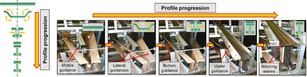
Schematic (left) and processing sequence (right) of the Continuous Profile Preforming System (CPPS). Source: Institut für Verbundwerkstoffe GmbH.
The fixation of the final profile preform shape is accomplished by means of stitching technology. This leads to a higher degree of flexibility of the profile preform compared to the approach involving binder-based fabrics. However, stitching technology involves limitations in the maximum preform thickness. Typical industrial flat stitching machines can process preform fabrics at a thickness of up to 7 mm, the limiting parameter being the maximum needle-lifting distance [24].
Cinquin et al. [29] presented another technique for continuous profile preforming developed in the project MOJO. There, carbon fiber-based layers of NCF material is continuously formed into an H-shaped preform, which finally acts as a joining element for sandwich structures. The NCF layers are fixed into the preform shape by activating the binder material through inductive heating, a technology patented by a group of authors from this project [30]. The heating technology is based on applying high frequency current to a coil, causing an electromagnetic field of equivalent frequency. The field acts on the carbon fibers and induces electric current. As a result of the electric resistance of the carbon fibers, they heat up and, thus, activate the binder material. Shaping the geometry of the coil according to the specific application allows for highly efficient heating.
Within project MOJO, this technology has been successfully tested for manufacturing preforms for RTM applications as well as for processing in a pultrusion line [29]. The H-shaped cross-section of the preform showed a width of 70 mm and a height of 7 mm, while the preform thickness varied from 3 mm along the flanges to 1.5 mm on the web. The continuous preforming process was driven by a pulling device typically known from pultrusion lines.
All of the technologies reviewed in this subsection allow for fully automated fabrication of near-net-shape preforms of profiles with constant cross-sectional geometry. The modular setup of the preforming lines enables flexibility in material, layup, and profile geometry. While rather simple cross-sectional geometries can be fabricated directly, more complex profile geometries require separate processing of sub-preforms and subsequent assembly tasks. In any case, the maximum length of the preforms is limited by the available amount of NCF material on the rolls.
2.3.2 Variable cross-sectional geometry
Advancing the CCPS system described in the previous section, IDVA GmbH (www.idva.de) and Airbus subsidiary enterprise CTC GmbH (www.ctc-gmbh.com) recently developed a prototype facility for the continuous manufacturing of a Z-shaped profile (see Figure 9, bottom) preform with variable cross-sectional geometry [31]. The development is based on an analysis of the draping forces occurring when forming the planar fabric into the desired Z-shape. A set of actuators, individually controllable for positioning pairs of guiding rollers, is used to continuously adjust the base length of the profile as shown in Figure 9 (top), a technology that has recently been patented [32].

Facility for continuously adjusting the cross-sectional geometry of profile preforms (top) and Z-shaped profile preform, axially curved and with variable profile base length (bottom). Source: IDVA GmbH.
The facility is designed to work with four layers of tri-axial carbon non-crimped fabrics, unrolled from reels of constant material width. Owing to varying the base length of the Z-shaped profile and tightly guiding one of the two preform flanges, the length of the second flange is changing as well. In order to obtain a constant flange length in the final preform, its edges need to be cut. The desired final preform geometry is fixed by thermally activating a thermoplastic binder finely dispersed on the fiber tows of the reinforcing fabric layers.
Borgwardt and Hühne [33, 34] describe a continuous manufacturing line for I-beam preforms with variable web height. In this line, NCF tape material is unwound from rolls and first formed into L-shapes by means of sheet metal guides. These are equipped with heating elements for activating the thermoplastic binder in the corner regions. The binder is subsequently consolidated by means of specifically contoured guiding rollers. Then, the two pre-shaped material strips are directed against each other such that they form a reversed T-shape. This preform is further formed into an I-shape, where the web sections are connected through compaction rollers and thermal activation of the binder. Finally, the preform is guided through a split-roller stand with a vertically moveable upper roller, actuated through a linear axis. This way, the web height can be continuously adjusted between 9 mm and 100 mm. As the NCF stripes show constant width, the upper flange needs to be cut in order to obtain near-net-shape preform quality. This is accomplished by means of an integrated cutting unit. The prototype line was successfully run at a maximum speed of 1.2 m/min for a 25.7-mm wide I-beam showing a web height between 10 mm and 35 mm. A quadri-axial carbon NCF material with 512 g/m2 areal weight and tricot stitching was used for the tests.
The processing speed is predominantly limited by the heat transfer from the heating units into the NCF material for activating the thermoplastic binder. Moreover, geometric restrictions are given in terms of the minimum radius between web and flange as a result of the limited drapability of the reinforcing material.
In a continuation of this work, a prototype facility for continuously preforming of C-, Z-, L-, or Omega-shaped profile preforms with variable axial curvature was developed at DLR as published by Stahl and Borgwardt [35]. The process is closely related to roll-forming, particularly known for manufacturing of curved metal profiles, and was recently patented [36]. Guiding the profile along its flanges by pairs of drive rollers, the curvature of the resulting profile is adjustable through the ratio of driving speed of the inner and the outer profile flange. The operation principle was verified at the prototype facility by processing bi-axial carbon NCF stripes (50 mm wide and 1500 mm long) with an areal weight of 415 g/m2 into a curved C-shaped preform at a maximum speed of 0.3 m/min.
2.4 Semi-continuous profile preforming
2.4.1 Preform rollforming
The basic principle of preform rollforming involves a processing head guided by an automated positioning system for draping layers of the reinforcing fabric onto a stationary preforming tool or core. The preform is manufactured in an additive procedure, i.e. layer-by-layer. The actual draping task is accomplished by means of guiding rollers mounted to the processing head. Fixation of the reinforcing fabric is realized by thermal activation of a thermoplastic binder. After draping a single layer of fabric, a cutting unit crops the material. Alternatively, pre-cut material batches can be used as well in order to avoid the need for inline cutting. However, feeding of the material batches to the processing head needs to be addressed separately in this case.
In a joint project, Premium Aerotec (www.premium-aerotec.com) and DLR (www.dlr.de) implemented a prototype preform rollforming system for U-shaped profiles as depicted in Figure 10 [37, 38]. There, the processing head is guided by means of an anthropomorphic robot, allowing for a high level of flexibility in terms of layup paths. The non-crimped fabric is unreeled from a roll mounted to the processing head, which contains an ultrasonic cutting unit for cropping the material after deposition of the individual layers.

Robot-based rollforming setup for an axially curved profile preform with U-shaped cross-section. Source: Premium Aerotec GmbH.
Although the production speed is lower compared to continuous profile preforming methods, this technology comes with a higher degree of flexibility in terms of layup changes, number of layers, as well as curvature along the major profile axis. A drawback of this approach is the constrained complexity of the folding unit in the processing head, limiting this technique to processing of geometrically rather simple profile cross-sections. Moreover, the material throughput is rather low compared to other profile preforming techniques.
2.4.2 Pick and drape
Within the context of the INSTRUKT research project, Airbus Helicopters (www.airbushelicopters.com, formerly Eurocopter) and the Institut für Werkzeugmaschinen und Betriebswissenschaften (www.iwb.tum.de) at Technical University Munich developed a processing head for (a) picking up pre-cut batches of fabrics by means of an anthropomorphic-robot and (b) draping and fixing these material batches onto a mold to additively build Z-shaped profile preforms (see Figure 11). The triangular-shaped processing head contains arrays of rectangular manipulation elements for picking up the batches by means of vacuum technology. Draping and fixing is accomplished using IR heaters located inside the processing head.

Processing head for the Pick&Drape technology. Source: Airbus Helicopters.
3 Technology comparison
In this section, two application scenarios are sketched and subsequently analyzed in terms of a quantitative comparison with respect to five techniques for automated profile preforming as introduced in the previous section:
AFP with direct layup of the reinforcement on the preforming tool,
selective flat AFP layup with subsequent draping of the layers onto the preforming tool,
robot-guided preform rollforming with precut batches of the reinforcements,
2D braiding following the over-braiding approach for realizing multi-layer braidings, and
continuous profile preforming with shape-adaptive tools for variable preform cross-sections with precut batches of reinforcements.
For this comparison of preforming technologies, a weighted decision matrix is presented with the individual decision criteria derived from specific requirements inherent to the application scenarios. One of these decision criteria is the manufacturing costs, which are estimated by means of a simple bottom-up cost estimation model. This model gives an indication of the major contributors for the manufacturing costs and acts as a tool for qualitative cost comparison.
3.1 Application scenarios
3.1.1 T-shaped stringer for aeronautic applications
The setup of structural components in aeronautic applications, such as sections of the main wing structures or components of the tail unit is a flat or slightly curved skin reinforced with stringers as depicted exemplarily in Figure 12 (top). The stringers are incorporated for establishing the required flexural stiffness of these large-scale structures while maintaining low component weight. This type of setup is advantageous in terms of lightweight design considerations, particularly when using carbon fiber-based reinforcements and is typically used in modern aircrafts.

Example of a structural aeronautic component composed of stringer-reinforced panels (top) and geometric parameters of the T-shaped stringers (bottom).
Up to now, stringer-stiffened panels are manufactured by processing skin and stringers along separate lines followed by an assembly process [39], which is expensive, labor-intensive, and does not fully exploit lightweight potentials. Alternatively, co-curing or co-bonding of prepreg materials can be considered [40–43]; however, these techniques require autoclave processing and, thus, cause high manufacturing costs as well.
Novel composite manufacturing strategies for aeronautic applications focus on out-of-autoclave technologies. Assuming an adequate resin infusion strategy, the stringer-stiffened panels can be manufactured by vacuum-assisted resin infusion (VARI). For this purpose, efficient preforming techniques for both, the skin as well as the T-shaped stringers, are required. While the skin preform represents a geometrically rather simple and large-scale structure, which can easily be addressed by means of AFP layup, manufacturing of the stringer preforms is a more challenging task due to the combination of increased geometrical complexity, the aspect ratio of the component dimensions, and the requirement for a predominant fiber orientation along off-axis directions of the stringer. For this work, an application scenario for automated manufacturing of T-shaped stringer preforms is designed on the basis of the following parameters:
As listed in Table 1, the T-shaped stringer preform is designed without curvature and 5 m in length, 50 mm in height, 30 mm in width and at a constant preform thickness of 5 mm. The geometric stringer preform parameters are visualized in Figure 12 (bottom).
Parameter list for an application scenario for automated manufacturing of T-shaped stringer preforms.
| T-shaped stringer preform for airplane panel application | |||
|---|---|---|---|
| Preform geometry | Production rate per year | ||
| Length | 5.000 m | Stringer preforms per panel | 6.00 pcs. |
| Height | 0.050 m | Panels per airplane | 6.00 pcs. |
| Width | 0.030 m | Airplanes per year | 80.00 pcs. |
| Preform thickness | 0.005 m | Stringer preforms per year | 2880.00 pcs. |
| Preform volume | 0.00188 m3 | Production rate per year | 14,400.00 m |
| Reinforcement parameters | Production rate per hour | ||
| Fiber volume content | 55.00% | # Working days | 200.00 d |
| Reinforcement volume | 0.00103 m3 | Stringers per day | 14.40 pcs. |
| Reinforcement material density | 1780.00 kg/m3 | Production rate per day | 72.00 m |
| Reinforcement mass per pc. | 1.84 kg | # Working hours per day | 8.00 h |
| Reinforcement mass per length | 0.37 kg | Production rate per hour | 9.00 m |
The production scenario is outlined with six stringers per panel, six panels per airplane, and 80 airplanes per year, resulting in a total production rate of 2880 stringer preforms per year.
3.1.2 C-shaped spar for wind turbine rotor blades
Today, rotor blades for traditional wind turbines predominantly consist of glass fiber-reinforced polymer composite materials and are manufactured in series production at lengths of up to 75 m. They are composed of four major components as depicted in Figure 13 (top):
the upper and lower shell structures, particularly designed with respect to aerodynamic properties,
tension booms, i.e. rather thick laminates of primarily unidirectional reinforcements along the blade axis bearing the tensile loads acting on the blade, and
spars connecting the shell elements and ensuring the flexural stiffness of the blade.

Inner setup of a wind turbine rotor blade (top) and geometric parameters of the spar preform (bottom).
For this work, an application scenario is designed for the automated manufacturing of C-shaped spar preforms with tapered cross-sectional dimensions on the basis of the following set of parameters:
As listed in Table 2, the spar preform height reduces from 1000 mm to 100 mm along a length of 50 m, whereas the width reduces from 200 mm to 30 mm. The preform thickness is assumed to be constant at 10 mm over the preform length. See Figure 13 (bottom) for a visualization of the geometric spar preform parameters. The production scenario is outlined with two spars per blade, three blades per wind turbine and 80 wind turbines per year, resulting in a total production rate of 480 spar preforms per year.
Parameter list for an application scenario for automated manufacturing of C-shaped spar preforms.
| C-shaped spar preform for wind turbine rotor blade | |||
|---|---|---|---|
| Preform geometry | Production rate per year | ||
| Length per spar preform | 50.000 m | Spars per blade | 2.00 pcs. |
| Height, max. | 1.000 m | Blades per wind turbine | 3.00 pcs. |
| Width, max. | 0.200 m | Wind turbines per year | 80.00 pcs. |
| Height, min. | 0.100 m | Spar preforms per year | 480.00 pcs. |
| Width, min. | 0.030 m | Production rate per year | 24,000.00 m |
| Preform thickness | 0.010 m | ||
| Preform volume | 0.380 m3 | ||
| Reinforcement parameters | Production rate per hour | ||
| Fiber volume content | 60.00% | # Working days | 200.00 d |
| Reinforcement volume | 0.228 m3 | Spars per day | 2.40 pcs. |
| Reinforcement material density | 2450.00 kg/m3 | Production rate per day | 120.00 m |
| Reinforcement mass per piece | 558.60 kg | # Working hours per day | 8 h |
| Reinforcement mass per length | 11.17 kg | Production rate per hour | 15 m |
3.2 Preforming cost estimation
Commonly, cost estimation techniques are classified into four basic strategies [44–46]: expert judgment as well as analogous, parametric, and bottom-up cost estimation techniques. While expert judgment is widely used, it is strongly depending on the particular expert and not repeatable by any other person in general. Analogous cost estimation is based on the principle of deriving costs for a particular product when cost information is already established for similar products. Parametric cost estimation is characterized by mathematically linking the product characteristics to the corresponding manufacturing costs through statistically derived equations, so-called cost estimation relationships (CERs). Bottom-up cost estimation finally relies on splitting the cost for manufacturing a product into functional elements, e.g. the set of working steps required. Then, the costs are estimated for all of the individual elements and finally accumulated to obtain the overall product cost estimation [44–49].
For the economic comparison of the different preforming techniques, a bottom-up cost estimation approach was chosen similar to those reported in [50–52]. The main reason for this decision was the need to compare strongly different processes without availability of historic data for the components manufactured with these processes. As a result, parametric as well as analogous cost estimation techniques cannot be reasonably applied. As the processes considered in this work are compared on a very generic level, the cost estimation was kept at a simple level with the overall costs consisting of just four major contributors: material, labor, equipment, and operational costs.
Following the review paper on cost modeling for aerospace-related components by Curran et al. [44], a simple bottom-up cost model was set up to qualitatively compare techniques for automated profile preforming. There, four major cost contributors are incorporated:
Material costs, calculated by means of:
raw materials costs dedicated to the type of reinforcement being used for the particular profile preforming technique, which are assessed based on typical market prices and
the total mass of reinforcing material required for the preform as determined by the geometric parameters and the fiber volume fraction to be realized in the profile preform together with an assumption on the material waste specific for the preforming technology.
Deduction costs are derived from:
facility investment costs, estimated from empirical values gained at manufacturing companies
and a deduction period, uniformly assumed with 5 years in this work.
The total operational costs are calculated from:
hourly operational costs for the respective facility, which are individually judged for the particular processing techniques based on technical complexity of the facility, and
the production time, which is derived from the total mass of reinforcing material required for the preform and an estimated value for the production rate in terms of mass of reinforcement material per hour. The latter represents the average production rate of the preforming facility for manufacturing the specific preform including down and service times (see, e.g. [15]).
Finally, labor costs are estimated by means of:
an estimated value for the average need of working personnel for operating the preforming facility and
average labor costs of € 60.- per hour – although these could be diversified for the particular processing techniques according to the required qualification of the working personnel, uniform costs were assumed for this analysis for the sake of simplicity.
Material costs were specified as average market prices based on cost information requested from several material suppliers. Facility investment costs were estimated based on data requested from facility manufacturing companies. However, the numbers incorporated in our cost analysis need to be considered as rough estimates. Specification of more accurate facility investment costs clearly requires intensive correspondence with manufacturing companies based on concrete purchase interest, which obviously is beyond the scope of this work.
Considering the two application scenarios introduced in the previous section, some major differences in the cost estimations need to be noted:
Material costs:
Whereas the rather small-sized T-shaped stringer preforms for aeronautic applications are realized with carbon fiber reinforcements, resulting in <2 kg of total preform mass, the C-shaped spar preform for the wind turbine blade is designed with glass fiber reinforcements and due to the preform length of 50 m, the total mass of reinforcement is given with about 560 kg in that scenario.
Facility investment and operational costs:
The length of the C-shaped spar preform for the wind turbine blade asks for adequately designed manufacturing facilities as well. Thus, the facility investment costs as well as the facility operational costs are estimated with significantly higher values compared to the preforming facilities for the T-shaped stringer preforms.
Labor costs:
As a result of the preform length of 50 m for the C-shaped wind turbine blade spar preform, the required amount of working personnel is estimated at a significantly higher value with respect to preforming of the rather small-scaled T-shaped stringer preform.
3.2.1 T-shaped stringer for aeronautic applications
The cost estimation is based on two key parameters as derived in Table 1: the total mass of reinforcement material for the T-shaped stringer preform (1.84 kg) and the production rate of 2.880 stringer preforms per year. Based on these parameters, the four major cost contributors are calculated for the application scenario sketched in Section 3.1.1 for five different automated preforming techniques. The results of this cost estimation are shown in Table 3.
Preforming cost estimation for T-shaped stringer preforms with various automated preforming techniques.
| AFP direct layup | AFP selective flat layup | Rollforming | Braiding (2D, overbraiding) | Continuous preforming | |
|---|---|---|---|---|---|
| Processing parameters | |||||
| Number of subpreforms per preform (*) | 2.00 – | 2.00 – | 2.00 – | 1.00 – | 1.00 – |
| Reinforcement mass per (sub)preform | 0.92 kg | 0.92 kg | 0.92 kg | 1.84 kg | 1.84 kg |
| Reinforcement material waste | 10.00% | 5.00% | 5.00% | 10.00% | 5.00% |
| Total reinforcement mass per (sub)preform | 1.01 kg | 0.96 kg | 0.96 kg | 2.02 kg | 1.93 kg |
| Estimated production rate (°) | 5.00 kg/h | 10.00 kg/h | 3.00 kg/h | 5.00 kg/h | 15.00 kg/h |
| Production time per (sub)preform | 0.40 h/pc. | 0.19 h/pc. | 0.64 h/pc. | 0.40 h/pc. | 0.13 h/pc. |
| Material, deduction, operational, and labor costs | |||||
| Type of reinforcing material | Rovings, binder-based | Rovings, binder-based | NCF, binder-based | Rovings | NCF, binder-based |
| Raw material costs | 45.00 €/kg | 45.00 €/kg | 60.00 €/kg | 40.00 €/kg | 60.00 €/kg |
| Material costs | 90.86 €/pc. | 86.73 €/pc. | 115.64 €/pc. | 80.77 €/pc. | 115.64 €/pc. |
| Facility investment costs | 1,000,000.00 € | 1,000,000.00 € | 250,000.00 € | 700,000.00 € | 500,000.00 € |
| Deduction period | 5.00 years | 5.00 years | 5.00 years | 5.00 years | 5.00 years |
| Deduction costs per year | 200,000.00 € | 200,000.00 € | 50,000.00 € | 140,000.00 € | 100,000.00 € |
| Deduction costs | 69.44 €/pc. | 69.44 €/pc. | 17.36 €/pc. | 48.61 €/pc. | 34.72 €/pc. |
| Operational costs per hour | 20.00 €/h | 22.00 €/h | 10.00 €/h | 15.00 €/h | 10.00 €/h |
| Operational costs | 16.15 €/pc. | 8.48 €/pc. | 12.85 €/pc. | 6.06 €/pc. | 1.28 €/pc. |
| Working personnel | 1.50 persons | 2.00 persons | 1.00 persons | 1.50 persons | 1.00 persons |
| Labor costs | 72.69 €/pc. | 46.26 €/pc. | 77.10 €/pc. | 36.35 €/pc. | 7.71 €/pc. |
| Total preforming costs | 428.86 €/pc. | 352.39 €/pc. | 428.54 €/pc. | 171.78 €/pc. | 159.36 €/pc. |
| Relative preforming costs | 269.1% | 221.1% | 268.9% | 107.8% | 100.0% |
(*) The T-shaped stringer preform is set up from 2 L-shaped subpreforms for AFP-based and rollforming technologies.
(°) Production rate of the preforming facility (incl. down times) for manufacturing the subpreform.
Shaded values indicates the technology going with the least performing costs.
Note that the T-shaped profile preform is designed to be set up from two L-shaped subpreforms for the two AFP-based as well as the rollforming techniques, whereas the continuous preforming technique is designed to directly cover the T-shaped cross-section of the profile. Finally, the 2D braiding approach is based on over-braiding of multiple layers followed by draping this tubular preform into the desired T-shaped geometry.
The least manufacturing costs are estimated for the continuous preforming technique, with braiding being worse by just about 8% in terms of relative costs. The manufacturing costs estimated for the three other techniques are significantly higher.
In general, the total preforming costs are driven by the material costs. Considering the cost structure in more detail, the cost drivers for the two AFP-based technologies are also found in the high deduction costs, as a result of the relatively high facility investment costs, as well as in the labor costs, which are dominated by the rather high production time (the T-shaped preform is set up from two L-shaped subpreforms) and an increased need for working personnel. The costs for the rollforming technology are primarily driven by the labor costs, which in turn result from the rather high production time. The continuous profile preforming technique comes along with the lowest preforming costs as a result of the highest level of estimated production rate, which in turn result in comparatively low operational and labor costs.
3.2.2 C-shaped spar for wind turbine rotor blades
The cost estimation is based on (a) a total mass of glass reinforcement of 558.60 kg and (b) a production rate of 480 spar preforms per year as derived in Table 2. Based on these parameters, the four major cost contributors are calculated for the application scenario sketched in Section 3.1.2 for five different automated preforming techniques. The results of this cost estimation are shown in Table 4. Note that the AFP-based preforming facilities considered here are designed with an anthropomorphic robot on an additional linear axis for motions along the preform as outlined by Dell’Anno et al. [14]. Based on information collected from AFP manufacturing companies, this is the best concept in terms of economic considerations.
Preforming cost estimation for C-shaped spar preforms with various automated preforming techniques.
| AFP direct layup | AFP selective flat layup | Rollforming | Braiding (2D, overbraiding) | Continuous preforming | |
|---|---|---|---|---|---|
| Processing parameters | |||||
| Reinforcement mass per preform | 558.60 kg | 558.60 kg | 558.60 kg | 558.60 kg | 558.60 kg |
| Reinforcement material waste | 5.00% | 2.00% | 5.00% | 5.00% | 3.00% |
| Reinforcement mass per preform estimated | 586.53 kg | 569.77 kg | 586.53 kg | 586.53 kg | 575.36 kg |
| Production rate | 10.00 kg/h | 20.00 kg/h | 5.00 kg/h | 5.00 kg/h | 10.00 kg/h |
| Production time per preform | 58.65 h/pc. | 28.49 h/pc. | 117.31 h/pc. | 117.31 h/pc. | 57.54 h/pc. |
| Material, deduction, operational, and labor costs | |||||
| Type of reinforcing material | Rovings, binder-based | Rovings, binder-based | NCF, binder-based | Rovings | NCF, binder-based |
| Raw material costs | 5.00 €/kg | 5.00 €/kg | 8.00 €/kg | 3.00 €/kg | 8.00 €/kg |
| Material costs | 2932.65 €/pc. | 2848.86 €/pc. | 4692.24 €/pc. | 1759.59 €/pc. | 4602.86 €/pc. |
| Facility investment costs | 1,500,000.00 € | 1,500,000.00 € | 500,000.00 € | 500,000.00 € | 750,000.00 € |
| Deduction period | 5.00 years | 5.00 years | 5.00 years | 5.00 years | 5.00 years |
| Deduction costs per year | 300,000.00 €/year | 300,000.00 €/year | 100,000.00 €/year | 100,000.00 €/year | 150,000.00 €/year |
| Deduction costs | 625.00 €/pc. | 625.00 €/pc. | 208.33 €/pc. | 208.33 €/pc. | 312.50 €/pc. |
| Operational costs per hour | 20.00 €/h | 22.00 €/h | 10.00 €/h | 15.00 €/h | 10.00 €/h |
| Operational costs | 1,173.06 €/pc. | 626.75 €/pc. | 1173.06 €/pc. | 1759.59 €/pc. | 575.36 €/pc. |
| Working personnel | 1.50 persons | 2.00 persons | 1.00 persons | 1.50 persons | 1.00 persons |
| Labor costs | 5278.77 €/pc. | 3418.63 €/pc. | 7038.36 €/pc. | 10,557.54 €/pc. | 3452.15 €/pc. |
| Total preforming costs | 10,009.48 €/pc. | 7519.24 €/pc. | 13,111.99 €/pc. | 14,285.05 €/pc. | 8942.87 €/pc. |
| Relative preforming costs | 133.1% | 100.0% | 174.4% | 190.0% | 118.9% |
Shaded values indicates the technology going with the least performing costs.
The manufacturing costs are generally driven by labor and material costs as a result of the large dimensions of the C-shaped spar preform and the correspondingly high manufacturing time. The least manufacturing costs are estimated for the AFP selective flat layup approach. The AFP direct layup approach and the continuous preforming technique result in moderately higher costs (about 28% and 33%, respectively), the preforming costs estimated for rollforming and braiding are significantly higher compared to the AFP selective flat layup technique.
The higher preforming costs estimated for the AFP direct layup technique are caused by the comparatively low production rate and, thus, high labor and facility operational costs. This obviously results from the need for a large amount of rather short layup paths making the technique inefficient for this application scenario. Similarly, the continuous profile preforming technique shows a lower production rate as well, which again results in higher labor costs. Furthermore, material costs (binder-based NCF materials) are considerably higher compared to the AFP-based techniques. The rollforming and braiding techniques show the highest preforming costs, primarily driven by the labors costs as a result of comparatively low production rates and, thus, high manufacturing times.
3.3 Weighted decision matrix
In order to quantitatively compare the automated profile preforming techniques with respect to the application scenarios, a weighted decision matrix approach was chosen [53]. A set of n criteria are incorporated with individual weighing factors wi, i=1 … n, whereas the wi are summing up to a total of 1. The techniques to be compared are evaluated by means of ratings ri with values of 1 to 5, whereas 1 represents the worst rating, and 5 indicates the best rating. The ratings are weighted with the particular weighing factors and subsequently accumulated to result in a final rating RT for the respective technology:
The technology with the highest rating can finally be interpreted as being best suitable with respect to the preforming task of the application scenario.
For the comparison tasks presented in the subsequent sections, evaluation criteria were chosen such that the most important technical aspects of the preforming technologies were covered together with the preforming costs estimated in the previous section. The weighing factors wi were specified in order to cover the importance of the particular evaluation criteria among one another. These are explained in more detail in the subsequent sections for the two application scenarios.
Finally, the ratings ri were computed as average values from judgments, which the authors requested from a group of composite manufacturing experts on an individual and anonymous basis. However, the ratings are still subjective to a certain degree as it is the case for ratings in general.
3.3.1 T-shaped stringers for aeronautic applications
The results of the technology comparison for automated preforming of T-shaped stringer profiles as described in Section 3.1.1 are summarized in Table 5. The five preforming technologies are compared with respect to a set of seven evaluation criteria, six of them related to technical aspects, and the last one representing the preforming costs as estimated in the previous section.
Weighted decision matrix for the manufacturing of T-shaped stringer preforms.
| T-shaped stringer preform | AFP direct layup | AFP selective flat layup | Rollforming | Braiding (2D, overbraiding) | Continuous preforming | ||||||
|---|---|---|---|---|---|---|---|---|---|---|---|
| Criteria | Weight | Rating | Weighted rating | Rating | Weighted rating | Rating | Weighted rating | Rating | Weighted rating | Rating | Weighted rating |
| Ability to directly realize preform geometry | 0.15 | 3 | 0.5 | 1 | 0.2 | 3 | 0.5 | 4 | 0.6 | 5 | 0.8 |
| Two L-shaped subpreforms | Flat layup, subsequent draping | Two L-shaped subpreforms | Tubular braiding, forming | Direct forming | |||||||
| Flexibility to realize axial profile curvature | 0.10 | 5 | 0.5 | 1 | 0.1 | 4 | 0.4 | 4 | 0.4 | 4 | 0.4 |
| Choice of layup paths | Choice of layup paths, draping | Limitations at choice of fabric | Limitations at locking angle | Limitations at choice of fabric | |||||||
| Ability to cover fiber orientation along profile transverse directions | 0.20 | 5 | 1.0 | 5 | 1.0 | 5 | 1.0 | 3 | 0.6 | 5 | 1.0 |
| Choice of layup paths | Choice of layup paths | Choice of fabric | Process-based limitations | Choice of fabric | |||||||
| Flexibility in number of reinforcement layers | 0.10 | 5 | 0.5 | 5 | 0.5 | 5 | 0.5 | 4 | 0.4 | 3 | 0.3 |
| Number of layup layers | Number of layup layers | Number of rollforming layers | Overbraiding | Limitations at pulling forces | |||||||
| Ability to realize inline precompaction | 0.15 | 5 | 0.8 | 5 | 0.8 | 5 | 0.8 | 3 | 0.5 | 4 | 0.6 |
| Compaction roller | Compaction roller | Compaction/Guiding roller | Roving tension | Guiding rollers | |||||||
| Productivity (line speed) | 0.15 | 1 | 0.2 | 3 | 0.5 | 4 | 0.6 | 4 | 0.6 | 5 | 0.8 |
| Short paths | Long and flat layup paths | Limitations at preform fixing | Overbraiding | Limitations at preform fixing | |||||||
| Manufacturing costs | 0.15 | 1 | 0.2 | 2 | 0.3 | 1 | 0.2 | 5 | 0.8 | 5 | 0.8 |
| See cost estimation | See cost estimation | See cost estimation | See cost estimation | See cost estimation | |||||||
| Sum | 1.00 | 3.50 | 3.25 | 3.85 | 3.80 | 4.55 | |||||
Shaded values indicates the technology showing the best overall rating with respect to the particular application.
The factors for weighing the individual evaluation criteria were chosen virtually uniform at a level of 0.15. The ability of the preforming technologies to cover fibers along directions transverse to the preform axis was weighted slightly higher as this is of particular importance for the stringers acting as stiffening elements in the aeronautic application scenario. By contrast, flexibility toward axial curvature as well as the number of reinforcing layers was weighted slightly lower as these aspects are considered less relevant for this application scenario.
The highest overall rating was found for the continuous preforming technique, indicating this to be the best suitable approach for the application scenario. The second highest rating was obtained for the rollforming technique, tightly followed by the braiding approach. The two AFP-based techniques show the lowest ratings.
The AFP-based techniques are well suited in terms of covering the required fiber orientation along the profile transverse directions as well as for their flexibility in realizing multiple reinforcement layers and for realizing a certain degree of precompaction of the material. However, their ability to directly realize the T-shaped cross-sectional geometry is limited, and they result in comparatively high preforming costs. The AFP direct layup approach is particularly disadvantageous due to the need for running the system along a high number of short paths, making the technique inefficient.
The braiding approach comes along with a number of suboptimal properties, particularly in terms of the process-based limitations with respect to the fiber orientation, reinforcement precompaction and overall line speed. The rollforming technique is disadvantageous as it is incapable of directly realizing the T-shaped preform geometry together with the layer-by-layer additive manufacturing approach causing high manufacturing times.
The continuous profile preforming approach shows the highest degree of efficiency of all the approaches compared in this work as it represents a clearly continuous way of manufacturing the profile preforms in a direct way. Moreover, the approach is advantageous in terms of relatively low preforming costs. However, limitations are seen in the number of guidable reinforcement layers. An increased number of layers results in higher frictional forces when guiding the material through the line. This can result in fiber misalignment or even fiber breakage.
3.3.2 C-shaped spar for wind turbine rotor blades
The results of the technology comparison for automated preforming of C-shaped spars as described in Section 3.1.2 are summarized in Table 6. Five preforming technologies are compared with respect to a set of seven evaluation criteria, six of them related to technical aspects and the final criterion representing the preforming costs as estimated in the previous section.
Weighted decision matrix for the manufacturing of C-shaped spar preforms.
| C-shaped spar preform | AFP direct layup | AFP selective flat layup | Rollforming | Braiding (2D, overbraiding) | Continuous preforming | ||||||
|---|---|---|---|---|---|---|---|---|---|---|---|
| Criteria | Weight | Rating | Weighted rating | Rating | Weighted rating | Rating | Weighted rating | Rating | Weighted rating | Rating | Weighted rating |
| Ability to directly realize preform geometry | 0.15 | 5 | 0.8 | 1 | 0.2 | 5 | 0.8 | 2 | 0.3 | 5 | 0.8 |
| Direct layup | Flat layup, sub-sequent draping | Direct forming, precut batches | Cone braiding, draping | Pre-cut batches | |||||||
| Flexibility to realize axial profile curvature | 0.05 | 5 | 0.3 | 1 | 0.1 | 4 | 0.2 | 4 | 0.2 | 4 | 0.2 |
| Choice of layup paths | Choice of layup paths, draping | Limitations at choice of fabric | Limitations at locking angle | Limitations at choice of fabric | |||||||
| Ability to cover fiber orientation along profile transverse directions | 0.20 | 5 | 1.0 | 5 | 1.0 | 5 | 1.0 | 3 | 0.6 | 5 | 1.0 |
| Choice of layup paths | Choice of layup paths | Choice of fabric | Process-based limitations | Choice of fabric | |||||||
| Flexibility in number of reinforcement layers | 0.15 | 5 | 0.8 | 5 | 0.8 | 5 | 0.8 | 4 | 0.6 | 3 | 0.5 |
| Number of layup layers | Number of layup layers | Number of rollforming layers | Overbraiding | Limitations at pulling forces | |||||||
| Ability to realize inline precompaction | 0.15 | 5 | 0.8 | 5 | 0.8 | 5 | 0.8 | 3 | 0.5 | 4 | 0.6 |
| Compaction roller | Compaction roller | Compaction/Guiding rollers | Roving tension | Guiding roller | |||||||
| Productivity (line speed) | 0.15 | 2 | 0.3 | 3 | 0.5 | 3 | 0.5 | 4 | 0.6 | 3 | 0.5 |
| Short/medium paths | Long and flat layup paths | Layer-wise, change of batches | Overbraiding | Change of batches | |||||||
| Manufacturing costs | 0.15 | 4 | 0.6 | 5 | 0.8 | 2 | 0.3 | 1 | 0.2 | 4 | 0.6 |
| See cost estimation | See cost estimation | See cost estimation | See cost estimation | See cost estimation | |||||||
| Sum | 1.00 | 4.40 | 3.90 | 4.20 | 2.90 | 4.05 | |||||
Shaded values indicates the technology showing the best overall rating with respect to the particular application.
The factors for weighing the individual evaluation criteria were chosen virtually uniform at a level of 0.15. The ability of the preforming technologies to cover fibers along directions transverse to the preform axis was weighted slightly higher due to its relevance for the wind turbine application scenario. On the other hand, flexibility toward axial curvature was weighted lower as this is of minor importance for this application scenario.
The highest overall rating was found for the direct AFP layup technique, indicating this to be the best suitable approach for this application scenario. The second highest rating was obtained for the rollforming approach, followed by the continuous preforming technique and AFP selective flat layup. The lowest overall rating was found for the braiding approach as it comes along with process-based limitations with respect to the fiber orientation, reinforcement precompaction and overall line speed combined with the highest preforming costs.
The continuous profile preforming approach is advantageous in terms of the choice of fabrics as well as the low preforming costs. However, the large cross-sectional dimensions and the resulting high frictional forces are disadvantageous. Moreover, the strongly varying profile dimensions ask for a batch-wise operation principle, which impedes the idea of continuous preforming.
The rollforming technique is advantageous as it is capable of directly realizing the C-shaped preform geometry together with its flexibility in terms of fiber orientation as well as the number of reinforcing layers. However, the preforming costs are clearly unfavorable for this approach.
The AFP-based techniques are well suited for this application scenario in terms of covering the required fiber orientation along the profile transverse directions as well as for their flexibility in realizing multiple reinforcement layers and for realizing a certain degree of precompaction of the material.
The AFP selective flat layup is sub-optimal as a result of the need for draping the large-scaled flat preform into the final C-shaped spar preform geometry. By contrast, the AFP direct layup approach is particularly interesting as it allows for a direct manufacturing of the C-shaped cross-sectional geometry.
4 Summary and conclusion
4.1 Summary
The paper at hand addresses various techniques for automated profile preforming for efficient LCM processing of fiber-reinforced polymer composites. In a review of existing preforming techniques, three different strategies based on AFP are described together with various continuous and semi-continuous preforming approaches as well as alternatives of the braiding technology.
Moreover, the automated preforming techniques are quantitatively compared on the basis of two different application scenarios: (a) T-shaped stringer preforms for aeronautical applications with constant and rather small cross-sectional dimensions and (b) C-shaped spar preforms for wind turbine rotor blade applications with significantly varying cross-sectional dimensions. The technology comparison is conducted individually for the two application scenarios by means of a weighted decision matrix approach incorporating a list of technical and economic criteria.
One of the evaluation criteria are the preforming costs, which are estimated by means of a bottom-up cost model combining four major cost contributors: (a) material costs, (b) deduction and (c) operational costs of the preforming facility, and (d) labor costs of the working personnel.
The outcomes of the technology comparison show different results for the two application scenarios. While the continuous preforming approach is best suited for the preforming of T-shaped stringer preforms, the AFP direct layup technique appears to be superior for the C-shaped spar preform application scenario.
4.2 Conclusion
The work presented in this paper covers a review of technologies for automated profile preforming, which is not covered in the literature so far. Moreover, the paper addresses a quantitative comparison of these preforming techniques with respect to two different application scenarios, specifically sketched by the authors based on empirical values. The comparison contains a simple bottom-up model for preforming cost estimation. This enables a quantitative analysis of the automated preforming techniques with respect to technical as well as economic criteria.
Acknowledgments:
This work is presented as part of the project “ILMAS – Implementation of the Liquid Infusion for Manufacturing of Aerospace Structures” funded within the European Community’s Seventh Framework Programme (FP7/2007-2013) for the Clean Sky Joint Technology Initiative under grant agreement no. CSJU-GAP-338413 and Topic Manager Alenia Aermacchi S.p.A., which is greatly acknowledged. The work presented is partly elaborated in frame of the studies done in the Christian Doppler Laboratory for High Performance Composite Processing, for which the authors kindly acknowledge the financial support provided by both the Bundesministerium für Wirtschaft, Familie und Jugend in Austria and the FACC AG.
References
[1] Lässig R, Eisenhut M, Mathias A, Schulte RT, Peters F, Kühmann T, Waldmann T, Begemann W. Serienproduktion von hochfesten Faserverbundbauteilen: Perspektiven für den deutschen Maschinen- und Anlagenbau. Studie.Search in Google Scholar
[2] Flemming M, Roth S, Ziegmann G. Faserverbundbauweisen. Berlin [u.a.]: Springer, 1995.10.1007/978-3-642-57776-5Search in Google Scholar
[3] Witten E, Kraus T, Kühnle M. Composites-Marktbericht 2014: Marktentwicklungen, Trends, Ausblicke und Herausforderungen.Search in Google Scholar
[4] Köster J. Compos. Manuf. 1990, 1, 117–125.10.1016/0956-7143(90)90247-TSearch in Google Scholar
[5] Weimer C, Preller T, Mitschang P, Drechsler K. Compos. Part A Appl. Sci. Manuf. 2000, 31, 1261–1268.10.1016/S1359-835X(00)00073-7Search in Google Scholar
[6] Weimer C, Preller T, Mitschang P, Drechsler K. Compos. Part A Appl. Sci. Manuf. 2000, 31, 1269–1277.10.1016/S1359-835X(00)00074-9Search in Google Scholar
[7] Kendall KN, Rudd CD, Owen MJ, Middleton V. Compos. Manuf. 1992, 3, 235–249.10.1016/0956-7143(92)90111-7Search in Google Scholar
[8] Potluri P, Atkinson J. Compos. Part A Appl. Sci. Manuf. 2003, 34, 493–501.10.1016/S1359-835X(03)00056-3Search in Google Scholar
[9] Mills A. Compos. Part A Appl. Sci. Manuf. 2001, 32, 955–962.10.1016/S1359-835X(00)00154-8Search in Google Scholar
[10] Schillfahrt C, Fauster E, Schledjewski R. JEC Compos. Mag. 2015, 2015, 43–45.Search in Google Scholar
[11] Neitzel M, Mitschang P, Eds., Handbuch Verbundwerkstoffe: Werkstoffe, Verarbeitung, Anwendung. München: Hanser, 2004.Search in Google Scholar
[12] Asareh M, Mills AR, Cartie D. In Proceedings of 13th European Conference on Composite Materials, European Society of Composite Materials, Ed., Stockholm, Sweden, 2008; 2008.Search in Google Scholar
[13] Belhaj M, Deleglise M, Comas-Cardona S, Demouveau H, Binetruy C, Duval C, Figueiredo P. Compos. Part B Eng. 2013, 50, 107–111.10.1016/j.compositesb.2013.01.014Search in Google Scholar
[14] Dell’Anno G, Partridge IK, Cartie D, Hamlyn A, Chehura E, James SW, Tatam R. Int. J. Struct. Integr. 2012, 3, 22–40.10.1108/17579861211209975Search in Google Scholar
[15] Engelhardt R, Hörmann P, Rinker F, Weyerer G, Drechsler K, Hirschvogel M. In Proceedings of SEICO 14 – 35th International Technical Conference & Forum, 2014.Search in Google Scholar
[16] Potluri P. In Wiley Encyclopedia of Composites, Nicolais, L, Ed., John Wiley & Sons, Inc: Hoboken, NJ, USA, 2011.Search in Google Scholar
[17] Cherif C. Textile Werkstoffe für den Leichtbau: Techniken – Verfahren – Materialien – Eigenschaften. Springer: Berlin, 2011.10.1007/978-3-642-17992-1Search in Google Scholar
[18] Potluri P, Rawal A, Rivaldi M, Porat I. Compos. Part A Appl. Sci. Manuf. 2003, 34, 481–492.10.1016/S1359-835X(03)00061-7Search in Google Scholar
[19] Guyader G, Gabor A, Hamelin P. Mech. Mach. Theory 2013, 69, 90–104.10.1016/j.mechmachtheory.2013.04.015Search in Google Scholar
[20] Laberge Lebel L, Trudeau P. SAE Int. J. Aerosp. 2013, 6, 508–512.10.4271/2013-01-2214Search in Google Scholar
[21] Brandt J, Drechsler K, Gessler A. Comparison of Various Braiding Technologies for Composite Materials in Aerospace Applications, SAE International: Warrendale, PA, 2001.10.4271/2001-01-2626Search in Google Scholar
[22] Uozumi T, Kito A, Yamamoto T. Adv. Compos. Mater. 2005, 14, 365–383.10.1163/156855105774470366Search in Google Scholar
[23] Gessler A. In Proceedings of Swiss SAMPE Technical Conference, Zurich, Switzerland, 2011.Search in Google Scholar
[24] Veit D, Wulfhorst B, Gries T. Textile Fertigungsverfahren: Eine Einführung, 2nd ed, Hanser, Carl: München, 2014.Search in Google Scholar
[25] Purol H. Entwicklung kontinuierlicher Preformverfahren zur Herstellung gekrümmter CFK-Versteifungsprofile, Logos-Verlag: Berlin, 2011.Search in Google Scholar
[26] Reinhold R, Mehlenhoff T. SAE Int. J. Aerosp. 2011, 4, 681–689.10.4271/2011-01-2515Search in Google Scholar
[27] Grieser T, Rieber G, Mitschang P. In Proceedings of 15th European Conference on Composite Materials, Venice, Italy, 2012.Search in Google Scholar
[28] Grieser T, Azizi S, Mitschang P. In Proceedings of TexComp 2013, Leuven, Belgium, 2013.Search in Google Scholar
[29] Cinquin J, Voillaume H, Stroehlein T, Ruzek R. In Proceedings of 17th International Conference on Composite Materials, International Society of Composite Materials, editor. Edinburgh, Scotland, 2009.Search in Google Scholar
[30] Kleineberg M, Herbeck L, Ströhlein T, Frauenhofer M, Dilger K, Herrmann A. Method and device for preforming carbon fibre semi-finished products for manufacturing fibre composite parts (EP1892078 A1; DE102006040049 A1); 2006.Search in Google Scholar
[31] Velten J. Carbon Compos. Mag. 2015, 12; Available from: www.plasticker.de/news/docs/ccev_magazin_0115-web.pdf.Search in Google Scholar
[32] Velten J, Andrä A, Deschauer N, Witte T. Method and apparatus for production of composite preform(EP 2746018 A1): Google Patents; 2012; Available from: http://www.google.com/patents/EP2746018A1?cl=en.Search in Google Scholar
[33] Borgwardt H, Hühne C. In Proceedings of Aachen-Dresden International Textile Conference 2012, Dresden, 29.-30.11.2012.Search in Google Scholar
[34] Borgwardt H. In Adaptive, Tolerant and Efficient Composite Structures, Wiedemann, M, Sinapius, M, Eds., Springer: Berlin, New York, 2013, pp. 317–324.10.1007/978-3-642-29190-6_25Search in Google Scholar
[35] Stahl A, Borgwardt H. In Proceedings of International Sampe Conference, Seattle, 2014, pp. 4217–4231.Search in Google Scholar
[36] Stahl A, Assing H, Borgwardt H. Gekrümmte Preform (DE201210101706; EP20130157374); 2012.Search in Google Scholar
[37] Apmann H. In Proceedings of 17th International Conference on Composite Materials, International Society of Composite Materials, editor, Edinburgh, Scotland, 2009.Search in Google Scholar
[38] Apmann H. In Proceedings of DLR Bauweisen Kolloquium, Stuttgart, Germany, 2009.Search in Google Scholar
[39] Mahfuz H, Majumdar P, Saha M, Shamery F, Jeelani S. Appl. Compos. Mater. 2004, 11, 155–171.10.1023/B:ACMA.0000026585.37973.c8Search in Google Scholar
[40] Huang CK. Compos. Part A Appl. Sci. Manuf. 2003, 34. 403–410.10.1016/S1359-835X(03)00081-2Search in Google Scholar
[41] Hart-Smith LJ. Int. J. Adhes. Adhes. 1999, 19, 181–191.10.1016/S0143-7496(98)00033-5Search in Google Scholar
[42] Soutis C. Mater. Sci. Eng. A 2005, 412, 171–176.10.1016/j.msea.2005.08.064Search in Google Scholar
[43] Huang CK, Hsu CY. Mater. Manuf. Process. 2005, 20, 739–746.10.1081/AMP-200055132Search in Google Scholar
[44] Curran R, Raghunathan S, Price M. Progr. Aerosp. Sci. 2004, 40, 487–534.10.1016/j.paerosci.2004.10.001Search in Google Scholar
[45] Niazi A, Dai JS, Balabani S, Seneviratne L. J. Manuf. Sci. Eng. 2006, 128, 563–575.10.1115/1.2137750Search in Google Scholar
[46] NASA. NASA Cost Estimating Handbook, 2008. Available at: www.nasa.gov/pdf/263676main_2008-NASA-Cost-Handbook-FINAL_v6.pdf.Search in Google Scholar
[47] Roy R. Cost Engineering: Why, What and How? Cranfield University: Cranfield, UK, 2003.Search in Google Scholar
[48] International Society of Parametric Analysts. Parametric Estimating Handbook: Fourth Edition, 2008.Search in Google Scholar
[49] Rush C, Roy R. Concurr. Eng. 2001, 9, 271–284.10.1177/1063293X0100900404Search in Google Scholar
[50] Esawi A, Ashby MF. Mater. Des. 2003, 24, 605–616.10.1016/S0261-3069(03)00136-5Search in Google Scholar
[51] Klanšek U, Kravanja S. J. Constr. Steel Res. 2006, 62, 434–448.10.1016/j.jcsr.2005.08.005Search in Google Scholar
[52] Boons AN. Int. J. Prod. Econ. 1998, 55, 241–255.10.1016/S0925-5273(98)00064-4Search in Google Scholar
[53] Tague NR. The Quality Toolbox, 2nd ed., ASQ Quality Press: Milwaukee, Wis., 2005.Search in Google Scholar
©2017 Walter de Gruyter GmbH, Berlin/Boston
This article is distributed under the terms of the Creative Commons Attribution Non-Commercial License, which permits unrestricted non-commercial use, distribution, and reproduction in any medium, provided the original work is properly cited.
Articles in the same Issue
- Frontmatter
- Review
- Automated profile preforming for structural components
- Original articles
- Effects of surface grafting of copper nanoparticles on the tensile and bonding properties of flax fibers
- Thermomechanical study of polyethylene porous membrane by coating silicon dioxide nanoparticles
- Crystallization, structural and mechanical properties of PA6/PC/NBR ternary blends: effect of NBR-g-GMA compatibilizer and organoclay
- Aging analysis of high voltage silicone rubber/silica nanocomposites under accelerated weathering conditions
- Investigation of viscoelastic properties and thermal behavior of photocurable epoxy acrylate nanocomposites
- The research of soft matter properties by light scattering material adding drop additive
- Microstructure and corrosion properties of SiC/Al-Mg-Cu-Si-Sn composites
- Tribological properties and microstructures of Al2O3-TiC-TiB2 reinforced composites
- Sustained release of OIC-A006 from PLGA microspheres to induce osteogenesis of composite PLGA/β-TCP scaffolds
- Study the effect of fiber loading and alkali treatment on the mechanical and water absorption properties of wheat straw fiber-reinforced epoxy composites
- Effect of mechanical alloying on the synthesis of Fe-TiC nanocomposite
- A comparative finite element analysis of two types of axial and radial functionally graded dental implants with titanium one around implant-bone interface
- Investigation of the effect of inert inclusions on densification during solid-state sintering of metal matrix composites
- Multiscale thermomechanical modeling of short fiber-reinforced composites
- Effects of the alkaline solution/binder ratio and curing condition on the mechanical properties of alkali-activated fly ash mortars
- Failure analysis and strengthening mechanism of Z-pinned composite T-joints under tensile loading
- Characteristic analysis of carbon nanotube thread embedded into three-dimensional braided composite under bending load