Multiscale thermomechanical modeling of short fiber-reinforced composites
-
Dawei Jia
 ,
Huiji Shi
,
Huiji Shi

Abstract
A study of the micromechanical behavior to predict the overall response of short fiber-reinforced composites under cyclic mechanical and thermal loading is presented. The instantaneous average over a “representative volume” of the material is considered. The influence of the short fiber’s aspect ratio, volume fraction, and spatial orientation has been investigated. The linear combined hardening model is used to describe the cyclic hardening effects in the case of metal matrix. A numerical procedure is used to predict the response of composites under mechanical and thermal conditions. The results of the numerical procedure have been compared to the results of three different models and to published experimental data.
1 Introduction
The use of fiber-reinforced materials has grown rapidly in the recent years in many applications, including aircraft, yachts, sporting goods, and motor vehicles, beside a wide range of military applications. Fiber-reinforced materials are a broad and versatile class of materials, which include a wide range of fiber and matrix combinations that provide a large number of component design and manufacturing options. High strength-to-weight ratio, coupled with excellent durability, corrosion resistance, and low maintenance cost, is among the factors that make fiber-reinforced materials ideal for widespread applications.
Short fiber-reinforced composites enjoy the advantage of providing stiffness levels comparable to continuous fibers while at the same time being moldable into complex shapes. They are attractive in relatively low fabrication costs and constitute a major portion of the demand of composites in automotive, marine, and aeronautic applications. Figure 1 includes the composite window frame designed by the Boeing aircraft company [1].

Composite window frame.
The particular benefits exhibited by metal matrix composites, such as increased specific strength and stiffness, improved high-temperature performance limits, and better wear-abrasion resistance, are dependent on the properties of the matrix alloy and of the reinforcing phase. A variety of metal matrix composite materials are used in automotive, space systems and satellites, medical, power semiconductors, sporting goods, and several military applications. Among the multiple uses are the space shuttle frames, Hubble telescope, bicycle frames, automotive pistons, brakes, and disks.
The properties of materials depend in a complex manner on the microstructure. The strength of a fiber-reinforced composite, for example, is determined by fracture criteria, themselves governed by a combination of microscopic phenomena. These include the plastic deformation of the matrix, the strength of the interface, and the distribution of the reinforcement within the composite. Therefore, predicting the strength of the composite from that of its constituent phases is generally challenging.
In the aviation industry, airworthiness specifications require an evaluation of the principal structural elements under cyclic mechanical and thermal loading as expected in service. The thermomechanical behavior of short fiber-reinforced composites has been investigated at high working temperature [2, 3]. However, the investigation was limited to varying mechanical loading at uniform temperature or constant mechanical loading under temperature time history. In addition, particle-reinforced composites [4, 5] have been studied under uniaxial tensile loading. However, these investigations were limited to mechanical uniaxial loading. In practical applications, short fiber-reinforced composites are subjected to cyclic mechanical loading coupled by simultaneous varying temperatures. Furthermore, it is difficult to align the short fibers during processing in a typical production environment.
Cavalcante et al. [6] modeled heterogeneous materials with macroscopically uniform microstructures using either the concepts of statistical homogeneity based on “representative volume” element or periodicity based on repeating unit cell. This research demonstrated that a micromechanics model plays a key role in understanding how the local properties of constituent phases and their arrangement influence the macroscopic structural behavior. The purpose of this paper is to predict the overall response of short fiber-reinforced composites under cyclic mechanical and thermal loading and to investigate the influence of the short fiber’s aspect ratio, volume fraction, and spatial orientation.
2 Thermomechanical constitutive relations
2.1 Representative volume
A representative volume element is the smallest possible volume that contains the necessary microstructure details such that the response of these elements under appropriate boundary conditions is identical to that of the material at large. The representative volume consists of matrix and short fiber phases and whose fibers are uniformly distributed, well bonded with the matrix, and identical in material and shape. A representative volume is not in a neighborhood close to the boundary. It contains sufficiently large number of short fibers to reflect the microstructure of materials yet is small enough compared to the macroscopic scale. The representative volume is selected to embody the overall response of the structure [6–8]. The shape of the short fibers is assumed to be ellipsoid, and the particulate-reinforced composite is one of its particular cases.
Throughout this paper, scalars and integers are represented by italic letters, vectors and second-order tensors by lower-case boldface letters, and fourth-order tensors by upper-case boldface letters. To describe the orientation of short fibers, two coordinate systems were defined. A global coordinate system (x1, x2, x3) and a local coordinate system (x1′, x2′, x3′) in which the x3′ axis coincides with the major axis of the ellipsoidal fiber were introduced (Figure 2). The local and global systems are related by the transformation: x=βx′, where β is the transformation matrix, whose components are functions of the angles θ and φ.

Schematic illustration of the global and local coordinate systems.
The distribution of the possible fiber orientation in the representative volume can be defined by a statistical density function ρ(θ, φ). In this study, a reduced density function ρ(θ) was considered for simplicity, which corresponds to a 2D case or a 3D axis symmetrical distribution.
2.2 Linear thermomechanical constitutive relation
The composite material was subjected to either a macroscopically uniform stress
where er=- Er: mr, Er: Mr=I, and I is the fourth-order unit tensor. σr and εr are the stress and strain tensors. er and mr are the unit thermal stress and strain tensors. Er and Mr are the stiffness and compliance tensors. In the local coordinate system, Er, Mr, er and mr are the same for any fiber-reinforced phase.
According to the Eshelby solution of an ellipsoidal inclusion, the Mori-Tanaka average method, and the self-consistent method, the strain and stress tensors of each phase in the linear elastic range can be determined as follows [9]:
where Ar and Br are the mechanical strain and stress concentration tensors of each phase, and ar and br are the corresponding thermal strain and stress concentration tensors. Their expression corresponding to the rth fiber-reinforced phase can be obtained as follows [10–12]:
where cr denotes the volume fraction of the corresponding phase. The numerical method to calculate the Eshelby tensor S for a general anisotropic matrix and the ellipsoid fibers with any aspect ratio was developed by Gavazzi and Lagoudas [13]. U is the dual tensor of S, and it can be calculated through Hill’s equation [10] as follows: S:Mm=Mm: (I-U). E* and M* are elastic constraint tensors whose expressions are E*=Em:(S-1-I) and M*=(E*)-1=(S-1-I)-1:Mm.
In the global coordinate system, Ar, Br, ar, and br are dependent on the shape and orientation of the fiber-reinforced phase. After using the reduced distribution function ρ(θ), the volumetric average of concentration tensors over all the short fiber-reinforced phases A̅f, B̅f, a̅f, and b̅f had been defined in the global coordinate system. The subscript r=f corresponds the fiber for the average value of all the reinforcement phases. The expression for A̅f as an example is
where VΩ is the volume of all fibers and <A> is the volumetric average of concentration tensor A over a single fiber.
Because the macroscopic strain and stress are equal to the volumetric average strain and stress, then the relations between the average concentration tensors of all fibers A̅f, B̅f, a̅f, and b̅f and the concentration tensors of the matrix Am, Bm, am, and bm are expressed as follows [9, 11]:
2.3 Nonlinear behavior of the matrix material
It is assumed that the fiber phase remains linearly elastic and the stress-strain relation of the matrix decides if the overall response of the composite is linear or not. In the case of ductile matrix material, the constitutive relation of composites can be extended and expressed in increment equations.
The instantaneous mechanical and thermal concentration tensors of each phase are denoted by
In the case of a metal matrix, the elastic-plastic state of a composite depends on the state of the matrix. When the matrix reaches the plastic range, the macroscopic response of the composite will be completely anisotropic, and local fields of the matrix and all fiber-reinforced phases are not only nonuniform but also depend on the loading history, that is,
where x denotes the material spatial position. In addition, when strain control is changed to stress control,
The instantaneous mechanical and thermal concentration tensors of fiber-reinforced phases are also dependent on the spatial position and loading history. The macrodependence implicitly indicates reliance on the specific microgeometry of material points, which could be expressed by the instantaneous stress and internal state variables of the corresponding material spatial position in the material, σ(x) and α(x) according to the internal state variable theory [14]. The average instantaneous concentration tensors of all fiber-reinforced phases in the plastic stage,
The expression for the average strain and stress increments of the matrix phase is similar, and the relationship between the instantaneous volume average concentration tensors of fibers and the matrix is similar to Equation (5).
It can be inferred that, in the plastic range, the average instantaneous response of all the fiber-reinforced phases is additionally dependent on the average instantaneous response of the metal matrix. The validity of this model was tested by comparing the analysis results to the available numerical and experimental results.
2.4 Cyclic hardening effect of metal matrix
Because the properties of a metal matrix composite in the plastic range are mainly dependent on the properties of the matrix, then attention is paid to the cyclic thermo-elastic-plastic constitutive relationship of the matrix. For a time-independent metal-matrix material, the strain increment can be decomposed into a mechanical part and a thermal part:
Where, Mep is the fourth-order instantaneous effective compliance tensor of the material.
It is a well established fact that most metallic materials exhibit the Bauschinger effect, which can be described by kinematic hardening. The formulation of the Bauschinger effect is based on introducing the so-called back-stress, b, to compute the stresses and strains after plastic flow. The back-stress describes the shift of the center of the yield surface.
The linear combined hardening model [15] was selected to describe the cyclic work-hardening behavior of the matrix materials. According to the J2-flow theory [16], the yield condition can be expressed by
Where, σs denotes the instantaneous radius of the yield surface and σ′ and b′ are the deviatoric tensors of σ and b.
Defining the cumulative plastic strain ε̅p,
Where σs,0 is the initial yield stress, w is the isotropic hardening coefficient, and Y(ε̅p) is the result in terms of the isotropic hardening model. It should be noted that σs and Y(ε̅p) are functions of ε̅p.
In the case of uniaxial cyclic loading, ε̅p=εp, and the constitutive curve of the material is shown in Figure 3. Each monotonic loading branch is numbered as k, k=1, 2, 3 … n-1, n. When the material reaches plasticity, for example on the nth loading branch, Y(ε̅p) is updated through the hardening coefficient H and the hardening exponent X of the material.
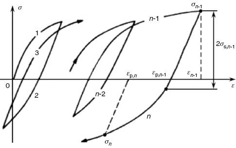
Constitutive curve of the material under uniaxial cyclic loading.
The material plastic modulus Eep, which is a function of ε̅p, is defined under unidirectional loading as Eep=dσ/dεp. Therefore, the expression of the instantaneous effective compliance tensor of a material could be written as
To obtain an expression to determine the back-stress deviatoric tensor b′ during the cyclic loading process, the increment of b′ can be written as
Where n is the unit tensor normal to the material yield surface, and Eq. (14) can be solved to obtain
Where,
3 Numerical simulation
To express tensors in FORTRAN program, they were transformed into the form of matrices. It is assumed that the uniaxial cyclic loading is strain controlled for both mechanical and thermal loading.
Because there are unknown quantities in both the average stress and strain increments, the global constitutive relations of the representative volume are simplified:
According to Equation (16), a set of equations was formed and solved to obtain the components not specified in the matrices. The average stress and strain increments of the matrix and fiber-reinforced phases were then calculated through the previous formulas. When the matrix reached the nonlinear range, an iterative procedure was required and the average stress increment of the matrix in the ith step is given by
where
where γ is the allowable value for error. When a new loading step is applied, the above iterative procedure is repeated.
4 Examples of the proposed model and discussion
Lagoudas et al. [17] have compared the results of the periodic hexagonal array (PHA) model, the self-consistent model, and the Mori-Tanaka model when a multiaxial proportional loading (σ33=2σ13) was applied on a composite system with aluminum matrix and unidirectional distributed silicon carbide whiskers. The whisker reinforcement had a volume fraction of 24% in the composite, and the other parameters chosen for the numerical calculations are as follows: aluminum, elastic modulus Em=72 GPa, Poisson ratio νm=0.33, σs,0=70 MPa and H=14.5 MPa, and SiC, Ef=430 GPa, and νf=0.25. In Figure 4, the numerical results of the proposed model are compared to the results of the PHA, Mori-Tanaka, and self-consistent models included in Ref. [17], and a good correlation is shown.

Comparison between the proposed model and other numerical models.
Figure 5 shows a comparison between the published experimental results [18] and the present numerical results. The composite used in the experiment was Al-6061 alloy reinforced by SiC whiskers with volume fraction of 28%. This experiment was conducted under strain control for mechanical strain range from -0.006 to 0.006 at 300°C. Because some of the composite material parameters had not been included in the publication, these parameters were selected to enable using the proposed model: Em=72 GPa, νm=0.33, w=0.7; Ef=430 GPa, νf=0.2. The curve presenting the results of this model was similar to the experimental results, except that the published results showed slight nonlinearity in the response. Better correlation to the experimental results can be achieved using the improved hardening model.

Comparison between calculated stress-strain responses and experimental results under isothermal loading: (A) experimental results and (B) calculated results of the proposed model.
The following is a discussion of the influence of volume fraction, aspect ratio, and distribution of the spatial orientation of the fiber-reinforced phases on the stress-strain response of composites under cyclic strain control loading at room temperature.
Figure 6 illustrates the effect of volume fraction of the fiber-reinforced phases on the total stress-strain response of the composite. The composite was Al+3.5% Cu reinforced by SiC fibers, whose geometry was taken to be spherical. The aspect ratio of spherical fibers is 1:1:1 and their orientation distribution has no effect on the macroscopic response of composites. The volume fractions of the reinforcements were 0%, 6%, and 20%. Monotonic strain-controlled loading ranging from 0 to 0.009 was applied. The material properties were Em=70 GPa, νm=0.33, σs,0=175 MPa, H=90 MPa, X=0.25, w=0.4; Ef=450 GPa, νf=0.17.

Stress-strain response of composite with different volume fractions of reinforcement.
Apparently, in Figure 6, the total elastic modulus and the initial yield stress of composites increased with the fiber volume fraction. Increasing the fiber volume fraction improves the capability of the composite to support the loading, and more strain energy could be consumed under equal plastic strain. This improves the impact energy absorption characteristic, which is desired in certain civilian and military applications.
Figure 7 displays the different average stress-strain response curves of composites with different aspect ratios (1:1:1 and 1:1:5) and in different spatial orientation distributions of the short fiber-reinforced phases. The composite was Al-2124 reinforced by SiC fibers, with the volume fraction of 13%. The material properties were Em=70 GPa, νm=0.33, σs,0=205 MPa, H=220 MPa, X=0.5; Ef=450 GPa, νf=0.17. The short fiber orientation distributions were unidirectional, distributed in the loading direction, cosine distribution ρ(θ)=cos(3θ/2), and random distribution. The response of the unidirectional short fiber composite is shown in Figure 7A and the response of the cosine and random distributions are shown in Figure 7B and C, respectively.

Stress-strain response of composite with different fiber aspect ratios: (A) unidirectional distribution, (B) cosine distribution, and (C) random distribution.
Two cycles of strain-controlled loading ranging from -0.008 to 0.008 were considered, and the coefficient of isotropic hardening was defined as w=0.2 to accelerate the stabilization of the cyclic loops. The reinforcement effect of particles was weaker than elliptical fibers with an aspect ratio of 1:1:5 as shown in Figure 7A. Higher elastic modulus and yield strength were found with a larger aspect ratio in the loading direction. The aspect ratio of cosine-distributed short fibers did not have much influence in reinforcement as unidirectionally distributed ones because only a part of the reinforcing short fibers had their major axes along the loading direction. When the short fibers were randomly distributed, the reinforcement effect of ellipsoidal fibers to the overall response of the composite was similar to the reinforcement effect of particles, as shown in Figure 7C. Increasing the volume fraction is more efficient and easier than controlling the orientation of the fibers in short fiber composites to improve its load-carrying capacity.
Finally, we analyzed the properties of composites under coupled thermomechanical loading. Two types of thermomechanical loading, in-phase (maximum tensile strain at maximum temperature) and out-of-phase (maximum compressive strain at maximum temperature), were adopted to simulate the loading history. The total strain varied from -0.01 to 0.01, and the temperature range was 90°C–210°C. The used composite was Al/SiC, and its properties were functions of temperature: Em=74657[1-(T+273)3/9333] MPa, νm=0.33, mm=2.35×10⁻⁵+2.476×10⁻⁸T K-1; Ef=450 GPa, νf=0.17.
Figure 8 illustrates the stress-strain response for the in-phase and out-of-phase loading history. In addition, the stress-strain response for the case of isothermal loading at the average thermal loading temperature (150°C) is shown in Figure 8 as reference for comparison. When the stress-strain responses for the in-phase and out-of-phase loading history were compared to that of the isothermal loading, the response curve of in-phase loading was much flatter than that of isothermal loading and the corresponding stress was lower for the identical strain at the plastic stage. The out-of-phase loading demonstrated the opposite phenomenon. These results can be explained by the fact that heat expansion compensates part of the mechanical strain and the thermal contraction requires less compressive mechanical strain. Furthermore, the decrease in the elastic modulus with increasing temperature also contributed to the observed results.

Stress-strain response under isothermal and thermomechanical loading: (A) in-phase and (B) out-of-phase.
5 Conclusions
There is a good correlation between the results of the proposed model and the predicting results of the PHA model, the Mori-Tanaka model, and the self-consistent model. In addition, a good agreement was found when the results of applying the proposed model to aluminum matrix composites were compared to relevant published experimental results. The linear combined hardening model was used in the simulation and the response might be improved using a better cyclic hardening model.
The macroscopic properties of composites are dependent on the fiber’s architecture and spatial orientation, especially the volume fraction of fibers. The reinforcement effect of particles is weaker than elliptical fibers, especially when unidirectional fibers are distributed in the loading direction. Increasing the fiber volume fraction improves the capability of short fiber composites to support the loading, in particular when more ellipsoidal fibers are used in the loading direction.
The numerical simulation of in-phase and out-of-phase thermomechanical loading history resulted in distinctly different stress-strain responses, which indicate the significant influence of thermal loading time history in the case of large temperature variation. The stress-strain response of the in-phase loading history was much flatter than that of isothermal loading at the average thermal loading temperature (150°C).
Funding source: National Natural Science Foundation of China
Award Identifier / Grant number: 50371042
Funding statement: This work was supported by the National Natural Science Foundation of China (grant number 50371042).
Acknowledgments:
This work was supported by the National Natural Science Foundation of China (grant number 50371042).
References
[1] Jackson KS, Wallace SFJ, Ostrem SE. Patent application publication, US 20080169380A1, 2008.Search in Google Scholar
[2] Mondali M, Abedian A, Adibnazari S. Comp. Mater. Sci. 2005, 34, 140–150.10.1016/j.commatsci.2004.12.063Search in Google Scholar
[3] Chen HF, Ponter ARS. Comp. Mater. Sci. 2005, 34, 425–441.10.1016/j.commatsci.2005.01.012Search in Google Scholar
[4] Han W, Eckschlager A, Bohm HJ. Comput. Sci. Technol. 2001, 61, 1581–1590.10.1016/S0266-3538(01)00061-6Search in Google Scholar
[5] Zhang F, Sun P, Li X, Zhang G. Mater. Lett. 2001, 49, 69–74.10.1016/S0167-577X(00)00344-XSearch in Google Scholar
[6] Cavalcante AAM, Pindera MJ, Khatam H. Compos. Pt. B Eng. 2012, 43, 2521–2543.10.1016/j.compositesb.2012.02.006Search in Google Scholar
[7] Dunn ML, Taya M. J. Mater. Sci. 1994, 29, 2053–2062.10.1007/BF01154679Search in Google Scholar
[8] Pettermann HE, Bohm HJ, Rammerstorfer FG. Compos. Pt. B Eng. 1997, 28B, 253–265.10.1016/S1359-8368(96)00055-8Search in Google Scholar
[9] Dvorak GJ, Bahei-El-Din YA. J. Mech. Phys. Solids 1979, 27, 51–72.10.1016/0022-5096(79)90010-3Search in Google Scholar
[10] Hill R. J. Mech. Phys. Solids 1965, 13, 213–222.10.1016/0022-5096(65)90010-4Search in Google Scholar
[11] Hill R. J. Mech. Phys. Solids 1963, 11, 357–372.10.1016/0022-5096(63)90036-XSearch in Google Scholar
[12] Dvorak GJ. In Metal Matrix Composites: Mechanisms and Properties, Everett RK, Arsenault RJ, Eds. Academic Press: Boston, 1991, p 1–77.Search in Google Scholar
[13] Gavazzi AC, Lagoudas DC. Comput. Mech. 1990, 7, 13–19.10.1007/BF00370053Search in Google Scholar
[14] Horstemeyer MF, Bammann DJ. Int. J. Plasticity 2010, 26, 1310–1334.10.1016/j.ijplas.2010.06.005Search in Google Scholar
[15] Zou Y, Yun G, Zhuang Z, Kasa S, Tsunori M. Int. J. Comput. Methods Eng. Sci. Mech. 2007, 8, 181–187.10.1080/15502280701375353Search in Google Scholar
[16] Hwang KC, Huang Y, Eds. The Constitutive Relation of Solid (in Chinese). Tsinghua University Press: Beijing, 1999, p 1–27.Search in Google Scholar
[17] Lagoudas DC, Gavazzi AC, Nigam H. Comput. Mech. 1991, 8, 193–203.10.1007/BF00372689Search in Google Scholar
[18] Qian LH, Wang ZG, Toda H, Kobayashi T. Mater. Sci. Eng. A Struct. 2000, 291, 235–245.10.1016/S0921-5093(00)00892-3Search in Google Scholar
©2017 Walter de Gruyter GmbH, Berlin/Boston
This article is distributed under the terms of the Creative Commons Attribution Non-Commercial License, which permits unrestricted non-commercial use, distribution, and reproduction in any medium, provided the original work is properly cited.
Articles in the same Issue
- Frontmatter
- Review
- Automated profile preforming for structural components
- Original articles
- Effects of surface grafting of copper nanoparticles on the tensile and bonding properties of flax fibers
- Thermomechanical study of polyethylene porous membrane by coating silicon dioxide nanoparticles
- Crystallization, structural and mechanical properties of PA6/PC/NBR ternary blends: effect of NBR-g-GMA compatibilizer and organoclay
- Aging analysis of high voltage silicone rubber/silica nanocomposites under accelerated weathering conditions
- Investigation of viscoelastic properties and thermal behavior of photocurable epoxy acrylate nanocomposites
- The research of soft matter properties by light scattering material adding drop additive
- Microstructure and corrosion properties of SiC/Al-Mg-Cu-Si-Sn composites
- Tribological properties and microstructures of Al2O3-TiC-TiB2 reinforced composites
- Sustained release of OIC-A006 from PLGA microspheres to induce osteogenesis of composite PLGA/β-TCP scaffolds
- Study the effect of fiber loading and alkali treatment on the mechanical and water absorption properties of wheat straw fiber-reinforced epoxy composites
- Effect of mechanical alloying on the synthesis of Fe-TiC nanocomposite
- A comparative finite element analysis of two types of axial and radial functionally graded dental implants with titanium one around implant-bone interface
- Investigation of the effect of inert inclusions on densification during solid-state sintering of metal matrix composites
- Multiscale thermomechanical modeling of short fiber-reinforced composites
- Effects of the alkaline solution/binder ratio and curing condition on the mechanical properties of alkali-activated fly ash mortars
- Failure analysis and strengthening mechanism of Z-pinned composite T-joints under tensile loading
- Characteristic analysis of carbon nanotube thread embedded into three-dimensional braided composite under bending load