Utilizing the phenomenon of diffraction for noise protection of roadside objects
-
Petr Louda
 and
Katarzyna Buczkowska
and
Katarzyna Buczkowska

Abstract
Presented here is a constructive solution to the challenge of utilizing the diffraction phenomenon for mitigating noise around roadside objects caused by the movement of vehicles on transportation routes. In contrast to existing prototypes, the innovation of the proposed solution lies in the creation of an active system that concentrates and directs oscillations originating from transportation sources. This active system, centered around sound absorption and reflection, establishes protective barriers and focuses on sound vibrations. The incorporation of diffraction effects within the Fraunhofer zones, along with the utilization of Fresnel lenses, directs attention towards these vibrations. The technical objective of harnessing the diffraction phenomenon for noise reduction around roadside objects involves demonstrating the feasibility of using a Fresnel zone plate (FZP) tailored for a specific oscillation frequency. This plate should demonstrate the ability to effectively manipulate sounds of varying frequencies while retaining its diffractive focusing capabilities. The intrinsic frequency characteristics of diffractive elements cannot be eliminated due to the inherent nature of sound diffraction. Consequently, it is imperative to thoroughly investigate and account for these properties. A groundbreaking discovery has been made, confirming the phenomenon of noise concentration originating from transportation sources. This revelation suggests that when a FZP is employed at frequencies other than its designed frequency, the concentration of oscillations remains. However, only the focal point of concentration shifts. Through experimentation, it has been established that the same FZP can be employed for varying wavelengths within a range of approximately ±20% while adhering to diffraction conditions. The feasibility of employing the thin lens formula to focus oscillations following the passage through a FZP has been substantiated. This solution also delves into the principal focusing, frequency, and shaping characteristics of the diffractive elements within FZPs. Furthermore, a computed estimation of the acoustic field scattered by a diffraction grating is compared against experimental data. This validates the approach and its efficacy in practical scenarios. The potential of harnessing the diffraction phenomenon to concentrate and regulate noise from transportation sources, thereby safeguarding roadside objects, is presented as a promising avenue for exploration.
1 Introduction
Living in close proximity to highways, industrial complexes, railways, and roads provides a firsthand understanding of the disruptive implications of noise on the nervous system. Noise has emerged as a contemporary affliction, an unintended consequence of technological progress. This dissonant phenomenon originates when oscillations disrupt the equilibrium of the surrounding medium, leading to deviations in its inherent parameters.
Efforts to counteract the adverse effects of noise have spurred initiatives aimed at reducing acoustic pollution in the environment and managing traffic-related noise. A pivotal approach involves the installation of noise barriers along roadsides, designed to shield against noise disturbances. These noise-protective acoustic screens, strategically positioned within transportation infrastructure and directly affixed to objects vulnerable to noise, not only mitigate pre-existing noise but also restrict emissions at their source. Their integration extends across vehicles, transportation infrastructure, architectural frameworks, and urban planning. This comprehensive strategy encompasses interventions at the level of road organization, encompassing measures like speed restrictions and scheduling adjustments for noisy traffic.
Noise protection screens can be categorized into two functional types: noise-reflecting and noise-absorbing. To counteract undesirable sound reflections, sound-absorbing materials are employed, effectively mitigating sound reverberations within the zones where noise barriers are positioned alongside roadways. Noise barriers represent a prominent approach to the mitigation and elimination of noise. Their effectiveness is assessed according to established standards, including metrics such as the noise reduction factor stipulated by ASTM C423-17, the sound insulation index defined in EN 1793-6, and the sound reflection index outlined in EN 1793-5. The efficacy of these indices hinges on the sound-absorbing attributes of employed materials, as well as the compositional makeup of the noise barrier’s frontal surface and the arrangement of surfaces transmitting noise protection.
The intricate nature of traffic generates a medley of noises. Upon encountering obstacles, counter-waves are reflected back towards the moving vehicle. When these waves overlay, the frontal waves emitted by moving sources, distortions arise, resulting in noise.
Scattered waves arising from moving sound sources within transportation interfaces with erratic fluctuations in medium properties, culminating in an interference pattern when superimposed upon incident waves at observation points. Due to the heterogeneous distribution of scatterers across time and space, these scattered waves lack coherence. The outcome of scattering hinges on the relationship between wavelength and scatterer dimensions. Wave diffraction arises when the wavelength approximates scatterer dimensions. Active control of sound absorption hinges on diffraction phenomena, rooted in the wave nature of sound and its propagation around obstacles.
The Fresnel Zone Plate (FZP) emerges as a fundamental diffractive focusing element, facilitating the concentration of oscillations generated by moving transport sources at specific frequencies. Given the diverse spectrum of noise, individual FZPs tailored to distinct frequencies pose pragmatic challenges. Investigating the feasibility of transmitting oscillations with varying frequencies through the FZP holds significance, as it informs the scope of focusing and frequency attributes within the diffraction threshold.
Mitigating noise-induced discomfort assumes heightened importance in suburban environments. From this perspective, there is valuable scope in scientifically substantiating and implementing novel technical and technological strategies that optimize noise barriers through the manipulation of acoustic variables.
2 Overview of the current state of knowledge
This literature review aims to assess and compare approaches for measuring the sound reflection and noise-absorbing properties of barrier materials along highways and roads. General issues of noise protection along main transportation routes are addressed in [1,2]. Calculations of noise attenuation when utilizing various shapes of acoustic barriers are discussed in [3,4]. Notably, Bugaru et al. [3] and Fuchs et al. [4] delve into the contribution of the Y-shaped geometric configuration of acoustic barriers to attenuation through diffraction phenomena.
The theory of sound absorption via diffraction is explored by Jian et al. [5]. Applying the Huygens-Fresnel principle to semi-infinite acoustic barriers is discussed by Fuchs et al. and Jiang et al. [6,7]. Additionally, Levin [8] presents a methodology for calculating and determining measurement errors in the directivity characteristics of an antenna located within the Fresnel zone. This is achieved by substituting the plane wave field with converging rays at the observation point. The potential benefits of Fresnel lenses for focusing beams across a wide range of incidence angles are highlighted by Calvo et al. [9], underscoring their potential for concentrating waves from various directions.
Porous materials form a distinct group of substances utilized for sound absorption. Guan et al. [10] offer estimations of the acoustic impedance and damping characteristics of various porous foams. Investigating the composite’s soundproofing properties, Suharno et al. [11] examine the influence of polystyrene foam and coconut husk quantities. Meanwhile, Rouyer et al. [12] present the determination of phase angle and modulus of the acoustic reflection coefficient of a shear wave during geopolymer curing. This is achieved through the transmission of broadband pulses within the MHz range. Further studies [13] delve into the acoustic attributes of asphalt-styrene butadiene emulsion-modified concrete, determining coefficients of absorption, reflection, noise suppression, and compressive strength across varying wave frequencies. Optimal component ratios are ascertained to achieve the desired sound absorption level.
In the study by Fang et al. [14], a composition employing porous material of diverse thicknesses is described, generating phase gradients on the reflected and transmitted surfaces of a periodic structure with four slots. Through diffraction theory, the length of the periodic structure can be adjusted to achieve the desired sound absorption level. Chen and Jiang [15] introduce the use of carbonized and activated nonwoven materials to dampen reflected sound waves in noise-absorbing panels. The study analyzes nonwoven composites with activated carbon fiber viscose precursor and polypropylene fibers as base layers, noting activated fiberglass composites’ capability to absorb normal sound waves.
Numerical modeling of reflection effects from noise barriers in near and far zones, accounting for barrier shapes, is detailed by Lutgendorf et al. [16]. Reflective properties of various noise barriers in the Austrian market, particularly in neighboring countries, are investigated by Conter and Wehr [17]. The construction of soundproof structures for noise reduction is presented by Reiter et al. and Chen et al. [18,19]. The utilization of a two-layer sound absorption system for low-altitude barriers near railways is discussed in the study by Hong et al. [20].
Modern sound absorption methods for railways and highways involve the development of thin panels for active control of reflected acoustic waves, including sound blocking. These systems employ algorithms to separate and adjust incident and reflected sound waves to desired levels [21]. Notable applications include predicting noise levels on screens with multiple reflections, considering various sources through ray and statistical models of urban traffic [22], and using acoustic diffusers based on the simulation of sound particle reflection, diffusion, and absorption by building facades [23]. Additionally, Vanlanduit et al. [24] focus on measuring acoustic material absorption using a scanning laser Doppler vibrometer. Fenln [25] explores new acoustic effects related to the solution and estimation of the far field of nonlinear interaction in the medium of primary difference frequency waves.
Despite their significance, noise shields often exhibit low durability due to design flaws, installation errors, uneven placement of sound-absorbing materials, and the inadequate sound-absorbing properties of chosen materials. Consequently, assessing the residual lifespan of structures under complex and uncertain operational conditions is of interest [26,27,28,29], especially considering the increasing adoption of noise protection screens with active noise absorption systems in proximity to mainline settlements.
This review of methodologies and tools, acknowledging shortcomings and implementation challenges, has paved the way for identifying future research directions. Emerging noise barrier solutions strive to explore the combined utilization of various physical phenomena – noise absorption, reflection, and beam adjustment – to address noise challenges effectively. The present work aims to leverage the phenomenon of diffraction for noise protection of roadside objects.
3 Methodology
3.1 Theoretical concepts
In the process of designing sound-absorbing barriers, it’s crucial to take into consideration that the noise protection effect manifests only within the acoustic shadow zone. Noise originating from a transportation highway can reach any point in space in the form of sound transmitted directly through the body of the screen and in the form of diffracted sound enveloping the upper and side edges of the screen.
Implementing diffraction effects in the Fraunhofer zones and using Fresnel lenses allows for the concentration of vibrations.
The laws of reflection and refraction of sound waves are explained using the Huygens principle to determine the position of the wavefront at any given time as the envelope of all secondary waves created by elementary sources. The sources of secondary waves are the points reached by the wavefront at the preceding time.
To explain the phenomena of diffraction, it’s necessary to apply the Huygens-Fresnel principle, according to which the excited wave is represented as the result of a superposition of coherent secondary waves. In this case, there is a departure from the laws of geometric optics. When sound is scattered, the sound wave from the source is transformed into multiple waves caused by numerous obstacles encountered in its path.
The propagation and absorption of sound waves in a homogeneous medium are accompanied by energy dissipation, i.e., a decrease over time due to conversion into other forms of energy. In acoustics, energy dissipation occurs due to internal friction and heat conduction.
The dependence of the frequency of sound waves ν perceived by the receiver of vibrations on the speed of the source of vibrations, which is a moving vehicle, is expressed by the Doppler effect.
where c is the speed of sound waves in a stationary medium, ν 0 is the frequency of oscillations emitted by the source, and θ is the angle formed between the vector u and a vector connecting the sound source and the receiver.
The legitimacy of using this formula for the problem under consideration is expressed through the correspondence of its dimensions to the units of measurement of the parameters included in it. Units of measurement of a physical quantity are conventionally chosen quantities having the same physical meaning as the measured quantity. A system of units of measurement is considered to be a set of units of measurement defined in a certain way for all quantities considered in a given field. The formulas of the dimensions of a physical quantity are the ratio defining the relationship between the unit of measurement of this quantity and the basic units. Dimensionality of the frequency of oscillation of the source [ν 0] = [s−1]. Dimensionality of the speed of sound in a dynamically moving extended medium [u] = [m s−1]. Dimensionality of the speed of sound in a stationary medium [c] = [m s−1], cos θ – dimensionless value. Using this information, after performing the appropriate calculations, according to the right part of this formula, we obtain the value of this dimensionality according to the right part of this formula [s−1]. The left part of this formula also has the same dimensionality value [ν] = [s−1]. Equality of values of dimensions in both parts of this equation testifies to the correctness of using this formula in the considered problem.
The issue of sound wave scattering by individual scatterers of a noise screen can be examined based on the wave equation of the potential ψ with unit amplitude.
where Δ is the Laplace operator.
The solution of the wave equation can be represented as
where
Function (3) describes some wave, the form of which is determined by additional conditions. The boundary condition for scattering can be interpreted as the Neumann condition, which states that the normal component of the sound wave’s velocity becomes zero when it encounters the surface of the noise screen.
In this context, ψ and ψ 0 represent the field potentials in the external environment and within the noise-absorbing screen, while ρ and ρ 0 refer to the density of the material in the environment and the screen, respectively, n is the external unit normal.
The acoustic efficiency of the screen is determined by its geometric dimensions, encompassing its height, length, and the distance between the screen and the traffic artery.
Fraunhofer diffraction arises when plane waves diffract under conditions where the source of oscillation and the observation point are situated far beyond the obstacle causing the diffraction, significantly exceeding the radiation’s wavelength. In this phenomenon, rays directed toward the observation point and striking the obstacle align to form nearly parallel rays.
To practically implement Fraunhofer diffraction, the oscillation source is positioned at the focal point of a converging lens, while the diffraction pattern is observed in the focal plane of a second converging lens positioned behind the obstacle (Figure 1).
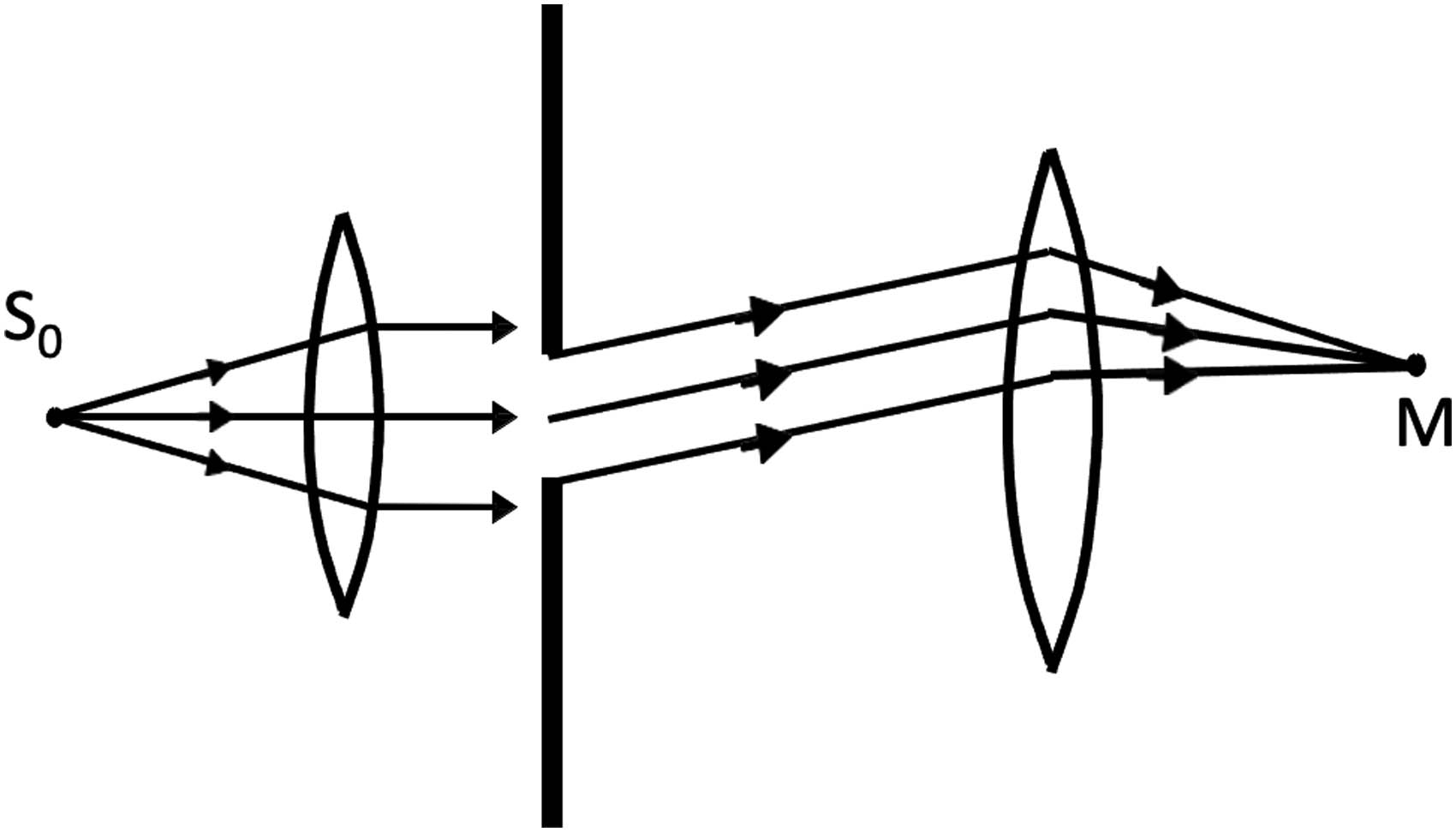
The principle of active sound absorption control based on Fraunhofer diffraction.
In this scenario, the placement of the converging lens in front of the screen should be chosen so that the moving extended source of traffic noise aligns with its focus. In these circumstances, the wave surfaces of the incident wave, responsible for generating acoustic noise, the plane of the noise shield, and the focal plane of the second collecting lens will become mutually parallel. The secondary waves generated within the elementary regions of the portion of the open slot for sound, emitted at an angle φ relative to the optical axis of the lens, gather at a specific point M. The oscillation at point M with the coordinate x is given by:
where A 0 represents the oscillation amplitude at the center of the diffraction pattern, φ denotes the diffraction angle measured from the outward normal to the incident wavefront, b stands for the gap width, λ is the wavelength, and ωt − 2π/λ xsin φ corresponds to the oscillation phase.
When φ equals 0, the fluctuations converging at point M will be in phase, resulting in an amplitude equal to the algebraic sum of the amplitudes of oscillations from the elementary zones. The resulting oscillation at point M is
where
The intensity of oscillation I is directly proportional to the square of the amplitude. The graph depicting its relationship with the diffraction angle φ at the characteristic points of the wavelength is presented in Figure 2.

Intensity distribution in Fraunhofer diffraction.
The majority of the noise that has passed through the slit is concentrated within the central maximum. The angular width of the central maximum φ m is determined by the expression
The positioning of the intensity minima is determined by the ratio of the slit width b to the wavelength λ. Given that |sin φ| ≤ 1, this implies that k ≤ b/λ. Under these circumstances, the presence of the first converging lens becomes essential, as the incident wave on the slit needs to be planar. If the slit width is considerably smaller than the focal length of the second converging lens, the rays extending to point M from the slot’s edges will remain parallel. Consequently, within the Fraunhofer diffraction observation setup, when generating noise from moving vehicles, the use of a second converging lens can be omitted.
The diffraction pattern maintains symmetry concerning the center of the lens. When the slit is shifted within the screen’s plane, the diffracted pattern remains stationary. Alternatively, with a fixed slit, adjusting the lens’s position results in a shift of the diffraction pattern. The configuration of the diffraction pattern is defined by the value of the wave parameter:
where L represents the distance from the plane of the slit to the parallel observation plane.
If P < 1, then the wave’s amplitude at the observation point situated opposite the center of the slot remains the same as in the absence of the slot. However, if P > 1, the primary intensity maximum will be positioned opposite the middle of the slit.
In scenarios involving two slits, the diffraction maxima will exhibit greater brightness compared to the case of single-slit diffraction. Within a diffraction grating composed of N identical slits uniformly spaced, the intensity of the principal maxima grows proportionally to N².
The consideration of boundary conditions, contingent on the nature of the obstacles, necessitates approximate methods due to the intricacy of solutions. One such method is based on Fresnel Zones of Focused Zones (FZF). FZF transforms a diverging spherical wavefront into a converging one. The wavefront emanating from a point source of oscillations S 0 is partitioned into transparent and opaque annular zones, where the difference in distance from the outer radii of adjacent zones to the point of wave concentration is half the wavelength, λ/2. Subsequently, these zones on the spherical surface are projected onto a plane. The diagram depicting the amplitude of the acoustic flat Fresnel zone, showcasing wave concentration due to maximum interference of secondary waves, is illustrated in Figure 3.
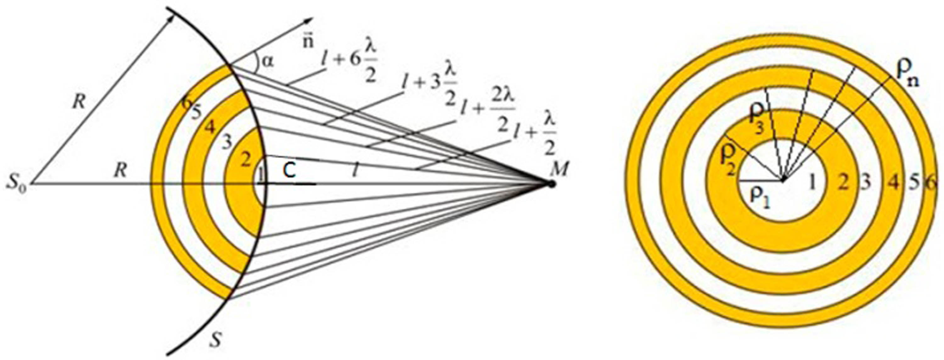
The principle of dividing Fresnel zones on a spherical surface.
Oscillations from even and odd Fresnel zones are in antiphase, causing mutual attenuation; conversely, placing a plate in the path of a sound wave that would encompass all even and odd zones results in a substantial increase in oscillation amplitude. The outcome of diffraction hinges on the extent of zone overlap. For considerable values, diffraction effects hold minor significance, and the laws of geometric optics aptly describe intensity distribution. Situations where approximately 10 zones remain open correspond to Fresnel diffraction, yielding intricate intensity distribution. Within the central section of the image, one can observe intensity minima and maxima. Graphical computation of diffraction can be accomplished using the Cornu spiral (Figure 4).
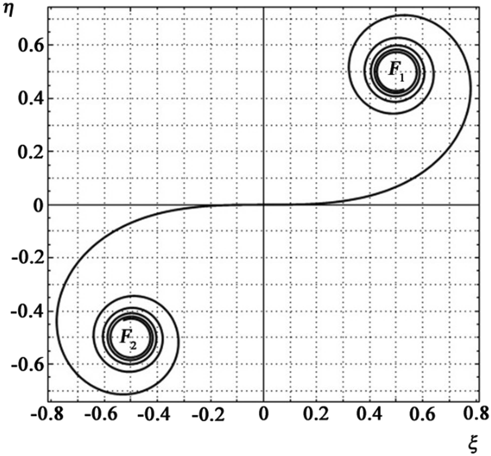
Diffraction calculation from a slit using the Cornu spiral.
The Cornu spiral consists of two branches symmetrically arranged around the origin, which asymptotically approach the poles. The parametric equation representing the spiral is given by Fresnel integrals and takes the following form:
where parameter
The meaning of the parameter υ is that
Points F
1 and F
2 to which the Cornu spiral asymptotically approaches at
The resultant oscillation generated by the section of the wavefront confined between the straight lines x = x 1 and x = x 2 is determined by the formula
were A 0 is the oscillation amplitude at a fully open wavefront, and B 1 B 2 is the length of the segment connecting two points on the spiral corresponding to the values.
Utilizing the Cornu spiral enables the determination of oscillation amplitudes for points situated at various distances from the boundary of the geometric shadow.
The zone plate also possesses imaginary focal points, enabling it to function concurrently as a combination of converging and diverging lenses.
The conventional demarcation between Fresnel and Fraunhofer diffraction is known as the Rayleigh distance. At this distance, when a plane monochromatic wave is incident on the central point of a round hole, only the first zone opens. In the Fraunhofer region, the diffraction patterns increase linearly with the distance from the slit. The angular size of the central diffraction maximum in the far zone is determined by the ratio of the wavelength to the diameter of the hole or slit. At the Rayleigh distance, this angular sector possesses a linear dimension equivalent to the width of the slit.
3.2 Rationale for the experiment
A fundamental requirement for practically harnessing the phenomena of diffraction and interference for noise mitigation alongside road structures is the establishment of a planar incident wavefront. When situating a point source at infinity, an alternative to achieving a plane wave at the FZP’s focus yields minimal energy concentration.
The attainment of a plane incident wavefront can be enhanced through the utilization of a Pictet mirror. The Pictet mirror, a concave spherical metal mirror equipped with supports, facilitates adjustments in height and inclination relative to an object positioned before it. The focal point lies at a distance of half the mirror’s radius from its midpoint. If the sound source is positioned at the mirror’s focal point, the reflected rays emerge as parallel beams, ensuring that the entire mirror reflects and amplifies the acoustic signal when observed along the optical axis. Incrementally rotating the mirror alongside the vibrations source positioned at its focus, to direct reflected sound rays towards different spatial regions, allows for a pronounced amplification of sound vibrations when the observer aligns with the mirror’s axis. Progressing along the oscillation source’s positional axis leads to the identification of the Pictet mirror’s focal point. By introducing a second concave mirror, similar to the Pictet mirror, within the path of rays emanating from the latter, the position of the second mirror’s focus can be determined using a sound-reflecting screen. The point of sound amplification will coincide with the Pictet mirror’s focus.
The experiment proposes fabricating a Pictet mirror shaped as a paraboloid, with a FZP affixed to its open section. The selection of a paraboloid aims to leverage its inherent property: a parallel beam of rays to the parabola’s axis, upon reflection, converges at its focus, and conversely, sound vibrations from a focal point source on the paraboloid are reflected by its inner surface, transforming into parallel rays. The acoustic signal also sustains a uniform phase. In this context, the distance between the Pictet mirror’s position and its focus aligns with the focal length of the FZP, and the paraboloid’s focus coincides with that of the FZP.
Of particular interest is ascertaining the most efficient acoustic energy conversion processes within the Pictet mirror. When the Pictet mirror serves as an absorber, only a fraction of the sound wave’s energy impinges on the FZP within the solid angle where the plate rests, with its apex positioned on the paraboloid’s axis. Conversely, when utilized as a reflector, the process occurs beyond the solid angle within the remaining volume of the sphere. When employing a point source, the vibrational energy is uniformly disseminated, generating a spherical wavefront.
It is recognized that sound vibration energy is directly proportional to the area of its dispersion. Hence, to assess the efficacy of absorption and reflection processes within the proposed paraboloid-FZP configuration, evaluating the ratio of the energy section areas involved in these processes is necessary.
where W ref1 is the energy of the reflected wave, Wabs is the energy of the absorbed wave, S represents the reflective area, and S segm symbolizes the area of a spherical segment that characterizes the energy of sound vibrations during absorption. ρ denotes the outer radius of the largest zone within the FZP, while R corresponds to the focal length of the FZP.
In this form of representation, the value of K is a dimensionless quantity; i.e., the dimensionality of the numerator and denominator of the fraction must coincide.
Hence, the coefficient K signifies the proportion of reflection energy to absorption. Given that S > S segm, when utilizing a paraboloid as an absorber, a substantial portion of energy dissipates, whereas when employed as a reflector, all the energy converges onto the FZP. In the configuration involving the paraboloid as a reflector, all energy is channeled toward the FZP, resulting in an amplification of the incident sound wave’s energy by a factor of K.
The amplitude A of a plane wave, propagating along the x-axis, undergoes alteration in accordance with the exponential law:
where A 0 signifies the amplitude of sound at the vibration source, and γ represents the absorption coefficient.
The material’s absorption coefficient is ascertained by the quotient of absorbed sound wave energy to incident wave energy. In accordance with Bouguer’s law, the intensity of incident oscillations I 0 diminishes exponentially within the absorbent material, as follows:
If the surface dimensions are significantly larger than the incident wavelength and possess considerable thickness, the absorption coefficient is determined via the reflection coefficient. Sound-absorbing materials encompass substances with an absorption coefficient exceeding 0.3. This absorption coefficient exhibits dependence on the frequency of the sound wave.
The quantitative representation of the reflection coefficient for the noise component is attainable through analyzing the pressures of the incident p 0, reflected p refl, and transmitted p p waves, along with their respective velocities υ 0, υ refl, and υ p.
where ρ 1 and ρ 2 denote the density of the medium through which sound propagates and the material composing the noise barrier, respectively. Similarly, c 1 and c 2 represent the velocities of sound vibration propagation in air and the soundproofing material.
Considering these relationships, the reflection coefficient α is determined as the ratio of acoustic impedances ρc between air and the environment.
To mitigate the influence of the noise component resulting from multiple reflections of the incident wave from secondary elementary sources, the model experiment employs a combination of a reflector and an absorber within the paraboloid structure, accompanied by the installation of a FZP on the exposed section of the paraboloid. The parameters and fundamental geometric relationships of this revolutionized paraboloid are selected based on the analogy to an open antenna with a mirror in radar systems. In such apparatus, shielding serves as a constructive method for localizing the electromagnetic field, designed to safeguard against external interference and radiation localization. The shielding effect is determined by the cumulative attenuation of energy due to material thickness absorption and the differential reflection caused by distinct acoustic characteristics of the medium.
For determining the geometric dimensions of the expanding segment of the paraboloid when coupled with the FZP, one should employ a definition of a parabola stating that the set of points equidistant to the focus and the directrix should be utilized. A coordinate system is established at the vertex of the parabola. The line extending through the focus and parallel to the directrix intersects the parabola at two distinct points. Half of this focal chord is equivalent to the parabola’s parameter, denoted as “P,” and its abscissa is P/2.
Let “f” denote the distance between the parabola’s focus and its apex. In terms of “F,” the focal length of the parabola, and “r,” the radius of the last Fresnel zone, which also serves as the focal radius of the point belonging to the parabola, the relationship can be expressed as follows:
where
Since x = r, considering the notation introduced earlier, it becomes feasible to determine the distance at which the FZP is positioned within the paraboloid.
By solving equations (21) and (22) simultaneously, we can derive the corresponding parabola equation.
The scientific rationale behind conducting the experiment to observe diffraction effects within the Fresnel and Fraunhofer zones was based on the notion that if the source of oscillations is positioned at the focal point of the FZP, and the plate itself would function as an acoustic collecting lens with its distinct focus “F”. This focus can be defined in a manner similar to that of refractive lenses.
where d stands for the object distance, and f denotes the image distance.
Substituting d = F 1 yields f = ∞, signifying that a plane wave should emerge from the FZP and propagate along its principal axis.
By substituting the components of this formula with the parameters of the FZP, f 1 = r 0 and d = R, we obtain
The radius ρ n of the zone in the Fresnel plate is determined as:
where λ signifies the wavelength of the sound wave.
In this expression, the value r 0 signifies the distance between the point of maximum amplitude and the zone plate, while R represents the distance from the vibration source to the zone plate.
The area of the Fresnel zones is determined by the following expression:
where a is the distance from the source to the outer edge of the zone, b is the distance to the focus area.
The zone plate multiplies the intensity of the vibrations, acting like a converging lens.
4 Materials and methods
4.1 Used equipment
During the simulation experiment, the following equipment was utilized:
Benetech GM1357 (AR824) sound level meter;
Mini portable speaker FM/mp3;
TD-V26 speaker functioning as a point sound source;
Computer;
Amplitude annular FZP employed as the source of oscillations; and
Pictet mirror.
The parameters of the FZP (as detailed in Table 1) were computed for a frequency of 6,000 Hz and a focal length of 1 m.
Characteristics of the FZP
| Zone number | 1 | 2 | 3 | 4 | 5 | 6 | 7 | 8 |
|---|---|---|---|---|---|---|---|---|
| Outer radius of the zone (m) | 0.2381 | 0.3367 | 0.4123 | 0.4761 | 0.5323 | 0.5831 | 0.6298 | 0.6733 |
The research employed methods for studying the phenomena of diffraction and interference on sound gratings as research techniques. The spatial resolution of this particular FZP was established via the Rayleigh criterion, using the width of the outermost opaque ring denoted as Δ.
According to Table 1, we have r 7 = 0.6298 m, r 8 = 0.6733 m, and Δ 78 = 0.0435 m. Taking into account that the wavelength for 6,000 Hz is 5.7 cm, the spatial resolution in terms of the wavelength becomes Re = 0.76λ.
4.2 Design features of the installation
In order to achieve a flat front and concentrate oscillations, a parabolic absorber was crafted from multiple screens of acoustic foam rubber. At the apex of the paraboloid, there was an aperture through which wires were affixed to the speaker. The speaker was capable of moving freely along the symmetry axis of the parabolic absorber. This enabled adjustments to the sound source’s position, thus extending the measurement range. Throughout the experiment, efforts were made to maintain a distance from the edge of the zone plate located on the exposed part of the paraboloid that equaled the plate’s focal length. This paraboloid configuration allowed for dual functionality, serving as both an absorber and a reflector of sound energy, particularly when considering the primary focusing, frequency, and shaping characteristics of the diffractive elements within the FZP.
The FZF represents the simplest diffractive focusing element, and exploring its information properties, along with investigating its limiting focusing and frequency attributes, facilitates a deeper comprehension of its nature and practical applications when utilizing a Pictet mirror (Figures 5 and 6).
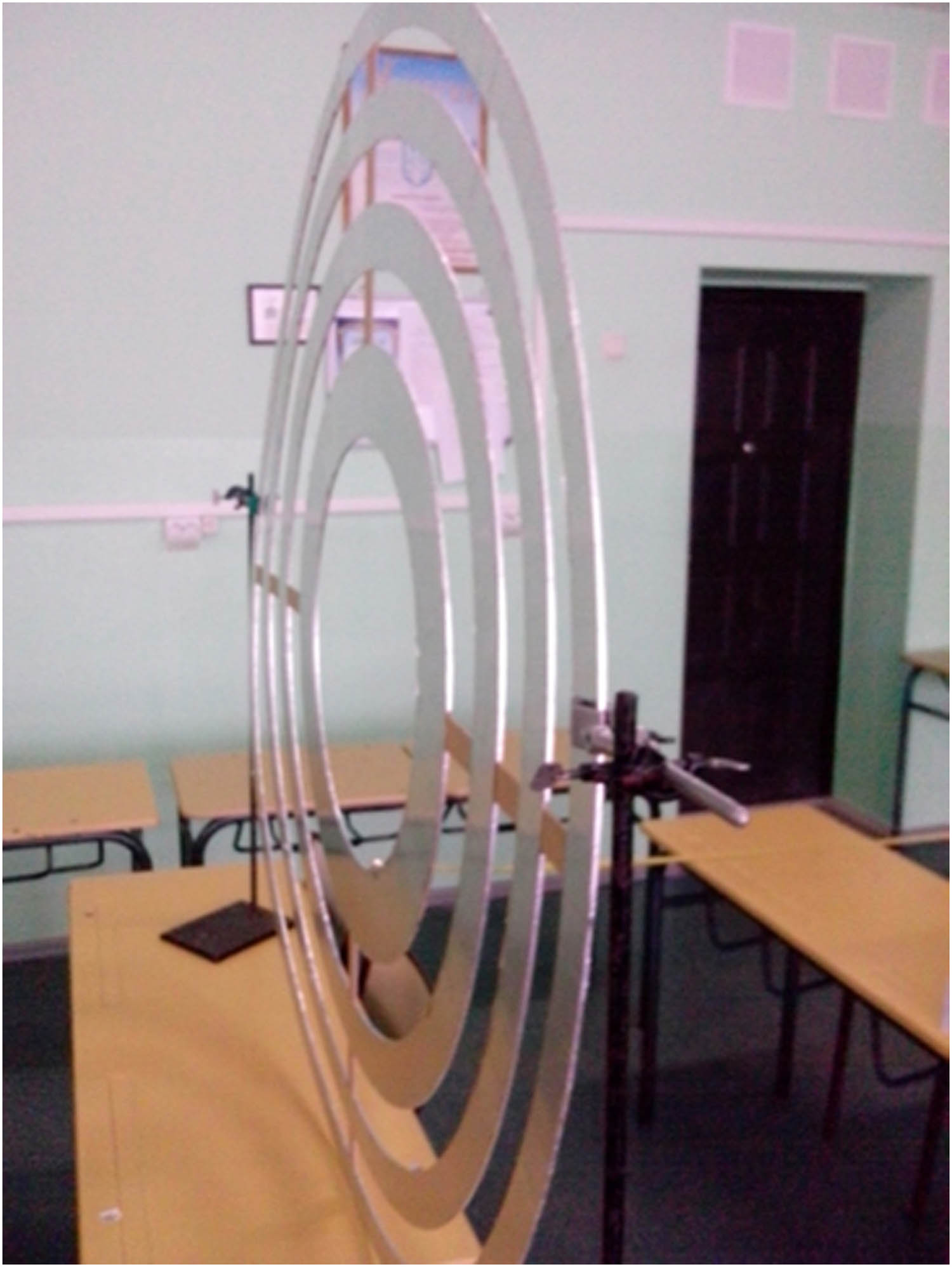
Photograph of the FZP utilized in the experiment.
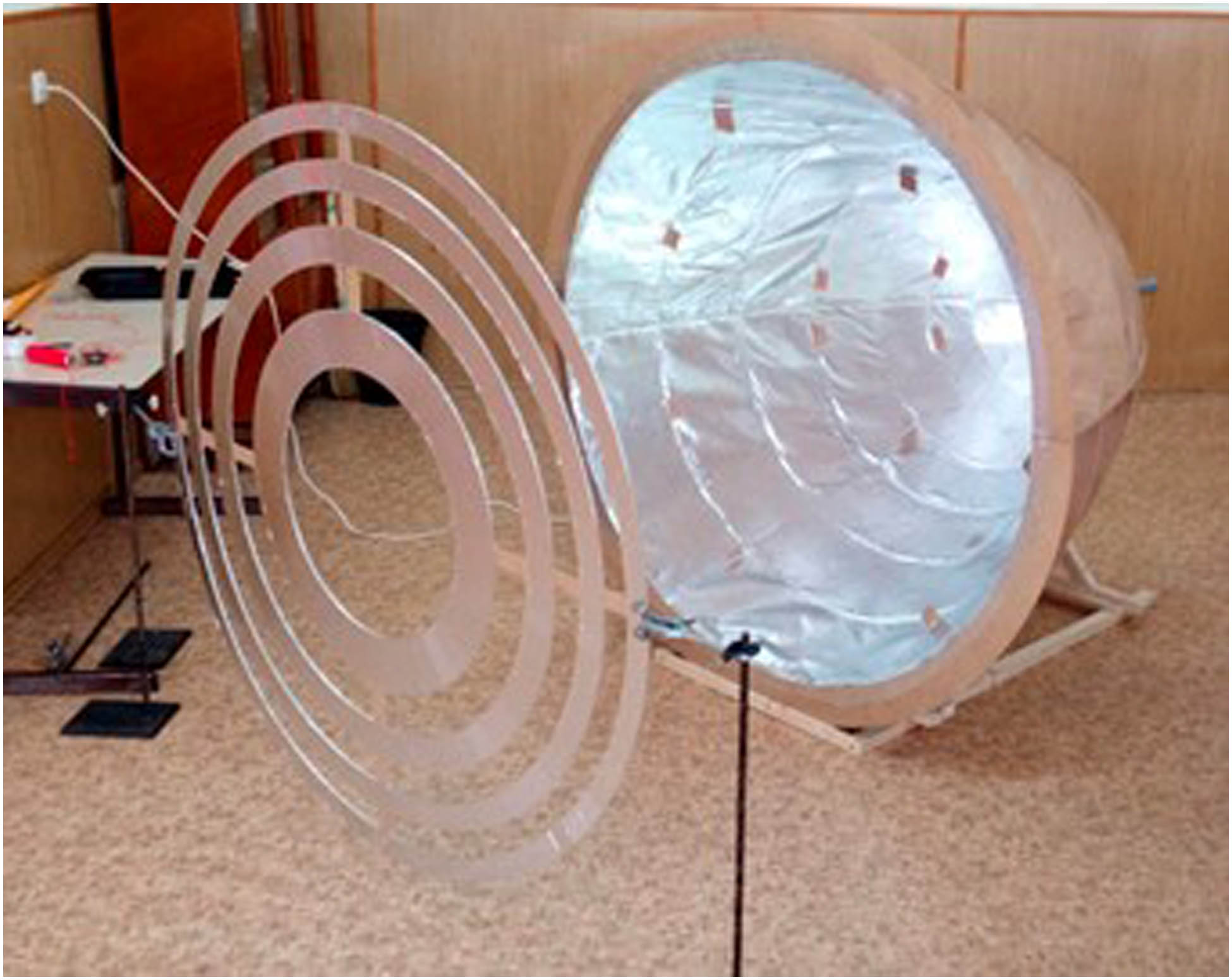
Appearance of the experimental setup.
5 Experimental part
Since the zone plate in the experiment should act as a thin lens, with the oscillation source located at its focus, a plane wave should propagate from the zone plate. The schematic of the experimental setup is shown in Figure 7.

Schematic diagram of the experimental setup: 1 – ZPF, 2 – speaker, 3 – frequency generator, 4 – sound level meter, 5 – sound-absorbing screen, and 6 – paraboloid of rotation.
The speaker, connected to the computer, was able to move freely along the axis of the paraboloid. In addition to this displacement, a series of measurements were conducted at different distances from the axis of the paraboloid: 0.5, 1.0, and 1.5 m. The background noise level in the room, in a silent state, was measured to be 34.5 ± 1.5 dB. The maximum relative measurement error was 3.45%. The measurement results were presented as intersecting graphical dependencies of intensities along the main axis of the zone plate, showing fluctuations around their average values, which were 68.08, 66.16, and 63.12 dB for microphone positions along the OS axis of 0.5, 1.0, and 1.5 m, respectively (Figure 8).
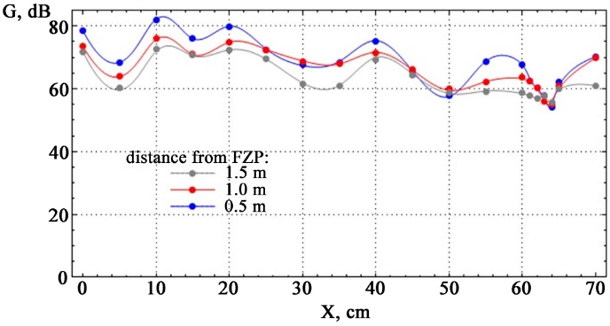
Demonstration of a plane wave in the experiment.
By moving the sound level meter at different distances from the axis, a series of curves were obtained that confirm the resemblance of the FZP to a converging lens. The observed trend in the propagation of oscillations confirms the fact that a plane wave is obtained when the oscillation source is located at the focus of the FZP. The nature of the propagation of the plane wave after passing through the zone plate can be explained by the interference of reflected waves from secondary elementary sources.
A distinct feature of the FZP is that it forms an image of multiple sources simultaneously, enabling its use as a lens. Therefore, after creating a FZP, an experimental determination of its focal length is necessary.
When d < F, divergent rays and imaginary foci occur. Placing the vibration source beyond the focus results in a converging lens with a real focus. During the experiment, the FZP could be moved along the oscillation source. When sound amplification was observed, the position was fixed, and the distance from the vibration source to the FZP and to the focus was measured.
As the sound source is located at the focus of the plate (i.e., at d = F
1 in formula
In practical conditions of noise suppression from transportation sources, the FZP should be placed at distances significantly larger than the focal length. By placing the sound source at the double focus of the plate (i.e., d
2 = 2F
2, according to the thin lens formula
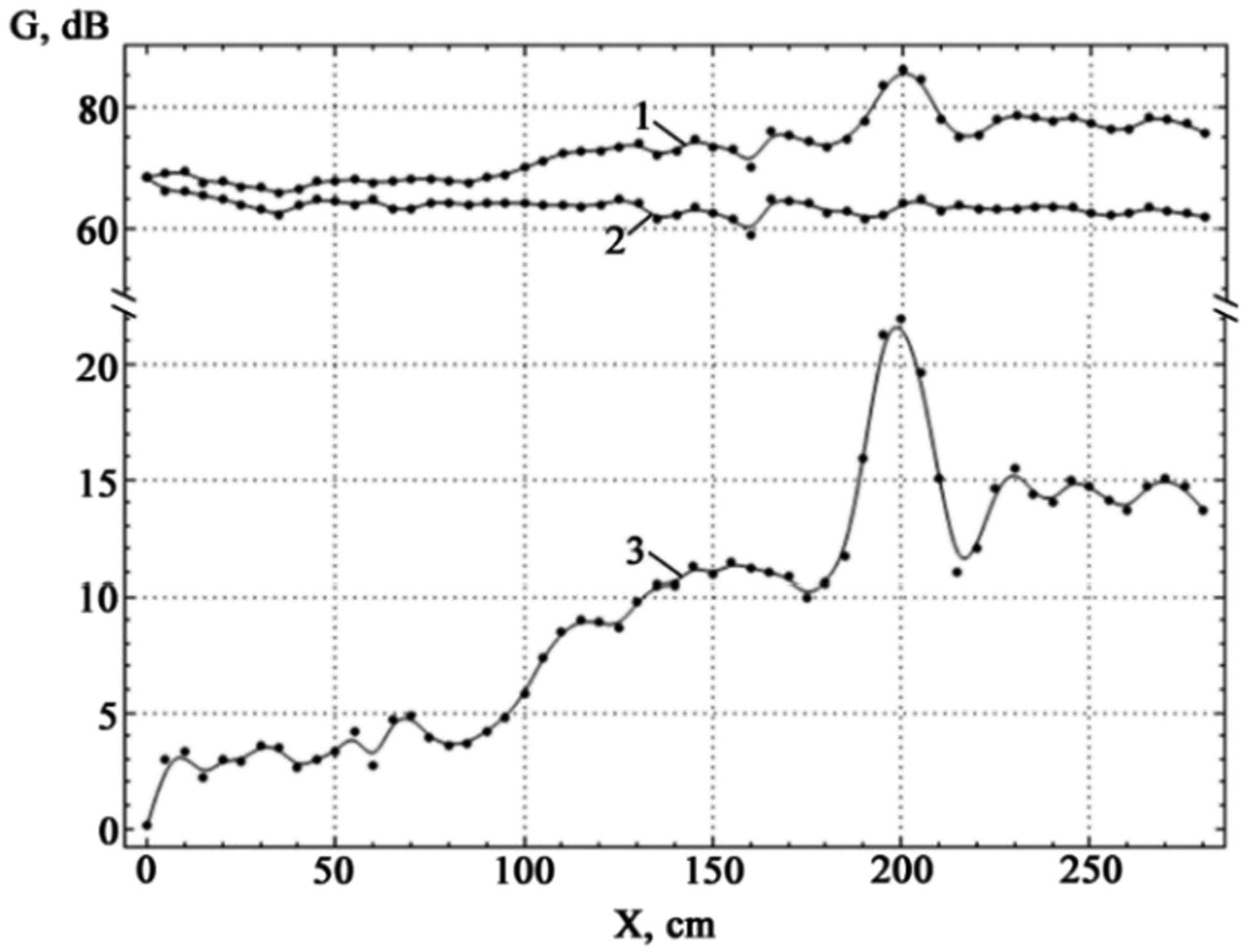
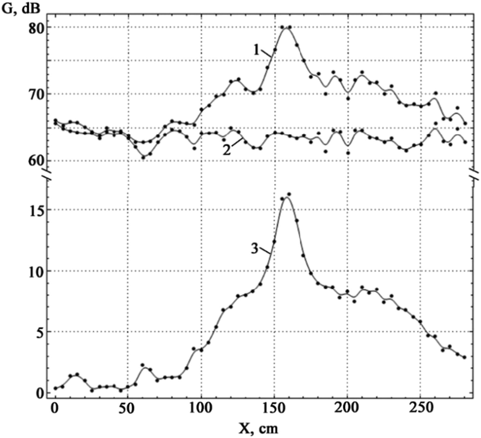
Experimental relationship between the amplitude of sound oscillations and the distance to the FZP (curve 1), noise values at different distances when the sound is activated (curve 2), and pure sound amplification from the FZP (curve 3) for a frequency of 6,000 Hz.
To represent the experimental results in terms of the exclusive contribution of the FZP to the analyzed oscillatory process, the noise component must be excluded. Noise values for various distances with different frequencies when the sound is activated are presented in Table 2 and Figure 9 (curve 2).
Experimental values of sound oscillation amplitudes are plotted against the distance to the FZP, along with noise levels at varying distances from the sound source for different frequencies
| Distance L (cm) | Volume (dB) | |||||||
|---|---|---|---|---|---|---|---|---|
| ν = 3,000 Hz | ν = 4,800 Hz | ν = 6,000 Hz | ν = 7,200 Hz | |||||
| Noise | Total | Noise | Total | Noise | Total | Noise | Total | |
| 0 | 60.7 | 61.1 | 65.7 | 66.1 | 68.3 | 68.4 | 61.5 | 61.8 |
| 5 | 60.8 | 61.3 | 64.8 | 65.3 | 66.1 | 69.1 | 62.9 | 63.9 |
| 10 | 64.5 | 65.9 | 64.5 | 65.9 | 66.2 | 69.5 | 62.7 | 63.5 |
| 15 | 64.3 | 65.8 | 64.3 | 65.8 | 65.4 | 67.6 | 61.9 | 62.97 |
| 20 | 61.1 | 62.1 | 64.1 | 65.1 | 64.8 | 67.8 | 61.3 | 62.3 |
| 25 | 60.2 | 60.4 | 64.2 | 64.4 | 64.0 | 66.9 | 62.0 | 63.4 |
| 30 | 63.3 | 63.8 | 63.3 | 63.8 | 63.1 | 66.7 | 62.7 | 63.8 |
| 35 | 64.4 | 64.9 | 64.4 | 64.9 | 62.3 | 65.8 | 63.3 | 64.9 |
| 40 | 63.8 | 63.9 | 63.8 | 64.4 | 63.8 | 66.4 | 64.2 | 64.4 |
| 45 | 64.3 | 65.3 | 64.3 | 64.5 | 64.7 | 67.7 | 64.4 | 64.8 |
| 50 | 63.3 | 64.5 | 63.3 | 63.8 | 64.5 | 67.8 | 63.1 | 64.14 |
| 55 | 62.1 | 65.7 | 62.1 | 62.8 | 63.9 | 68.1 | 64.7 | 65.1 |
| 60 | 60.4 | 67.1 | 60.4 | 62.7 | 64.8 | 67.5 | 63.7 | 64.75 |
| 65 | 61.0 | 67.4 | 61.0 | 62.9 | 63.1 | 67.8 | 64.8 | 64.9 |
| 70 | 62.7 | 69.8 | 62.7 | 63.7 | 63.2 | 68.1 | 64.4 | 64.6 |
| 75 | 63.1 | 71.8 | 63.9 | 65.2 | 64.3 | 68.2 | 63.6 | 64.4 |
| 80 | 64.7 | 74.8 | 64.7 | 66.0 | 64.3 | 67.9 | 63.8 | 64.7 |
| 85 | 64.5 | 74.9 | 64.5 | 65.8 | 63.8 | 67.5 | 64.9 | 65.3 |
| 90 | 63.6 | 73.68 | 63.6 | 65.6 | 64.2 | 68.4 | 64.8 | 65.2 |
| 95 | 61.8 | 73.4 | 61.8 | 65.4 | 64.1 | 68.9 | 63.4 | 64.7 |
| 100 | 62.2 | 74.9 | 64.2 | 67.7 | 64.2 | 70.0 | 64.6 | 64.9 |
| 105 | 63.2 | 73.6 | 64.2 | 68.3 | 63.8 | 71.2 | 63.5 | 64.58 |
| 110 | 64.3 | 73.4 | 64.3 | 69.7 | 63.9 | 72.4 | 64.0 | 64.4 |
| 115 | 63.1 | 70.3 | 63.1 | 69.9 | 63.7 | 72.7 | 64.4 | 64.5 |
| 120 | 64.9 | 72.7 | 64.9 | 71.9 | 63.9 | 72.8 | 63.1 | 63.6 |
| 125 | 64.4 | 71.4 | 64.4 | 72.3 | 64.8 | 73.5 | 63.6 | 64.3 |
| 130 | 62.8 | 70.8 | 62.8 | 70.8 | 64.1 | 73.9 | 64.9 | 65.8 |
| 135 | 61.9 | 68.4 | 61.9 | 70.2 | 61.5 | 72.0 | 63.4 | 65.1 |
| 140 | 61.8 | 67.7 | 61.8 | 70.7 | 62.3 | 72.8 | 63.8 | 65.1 |
| 145 | 63.7 | 69.0 | 63.7 | 74.0 | 63.4 | 74.7 | 63.3 | 66.1 |
| 150 | 64.3 | 69.7 | 64.3 | 76.7 | 62.5 | 73.4 | 62.6 | 65.79 |
| 155 | 64.1 | 70.0 | 64.1 | 80.0 | 61.7 | 73.1 | 63.7 | 66.7 |
| 160 | 63.7 | 69.0 | 63.7 | 80.0 | 59.0 | 70.2 | 63.9 | 65.4 |
| 165 | 63.3 | 68.4 | 63.3 | 77.4 | 64.8 | 75.8 | 63.7 | 65.1 |
| 170 | 63.8 | 69.1 | 63.8 | 75.1 | 64.5 | 75.3 | 61.4 | 64.3 |
| 175 | 62.8 | 67.6 | 62.8 | 72.6 | 64.2 | 74.2 | 63.2 | 66.4 |
| 180 | 64.1 | 69.1 | 64.1 | 73.1 | 62.7 | 73.3 | 62.2 | 65.8 |
| 185 | 63.4 | 68.1 | 61.4 | 70.1 | 63.0 | 74.7 | 63.7 | 66.4 |
| 190 | 64.6 | 69.3 | 64.6 | 73.3 | 61.7 | 77.6 | 63.8 | 67.3 |
| 195 | 64.4 | 69.2 | 64.4 | 72.2 | 62.1 | 83.4 | 64.4 | 70.2 |
| 200 | 63.1 | 67.4 | 61.1 | 69.4 | 64.1 | 86.1 | 61.1 | 70.4 |
| 205 | 64.6 | 68.1 | 64.6 | 72.1 | 64.8 | 84.4 | 64.6 | 72.1 |
| 210 | 64.6 | 68.3 | 64.6 | 73.3 | 62.9 | 78.0 | 64.6 | 73.3 |
| 215 | 63.5 | 66.67 | 63.5 | 71.67 | 63.9 | 74.9 | 63.5 | 71.67 |
| 220 | 63.3 | 66.8 | 63.3 | 71.8 | 63.2 | 75.2 | 63.3 | 71.8 |
| 225 | 62.7 | 66.1 | 62.7 | 70.1 | 63.2 | 77.8 | 62.7 | 72.1 |
| 230 | 63.3 | 66.2 | 63.3 | 71.2 | 63.2 | 78.7 | 63.3 | 73.2 |
| 235 | 61.9 | 64.8 | 61.9 | 68.8 | 63.7 | 78.1 | 61.9 | 73.8 |
| 240 | 61.5 | 64.3 | 61.5 | 68.3 | 63.6 | 77.6 | 61.5 | 77.3 |
| 245 | 62.3 | 64.5 | 62.3 | 68.5 | 63.4 | 78.4 | 63.3 | 79.5 |
| 250 | 62.4 | 64.2 | 62.4 | 68.2 | 62.4 | 77.1 | 61.4 | 77.2 |
| 255 | 63.8 | 65.5 | 63.8 | 68.5 | 62.1 | 76.2 | 63.4 | 76.1 |
| 260 | 63.6 | 65.2 | 65.6 | 70.2 | 62.5 | 76.2 | 64.6 | 75.2 |
| 265 | 62.9 | 64.4 | 62.9 | 66.4 | 63.4 | 78.1 | 63.5 | 73.0 |
| 270 | 62.4 | 64.2 | 62.4 | 66.2 | 62.9 | 77.97 | 63.4 | 72.2 |
| 275 | 63.8 | 64.97 | 64.8 | 67.97 | 62.4 | 77.1 | 64.5 | 72.67 |
| 280 | 62.7 | 64.6 | 62.7 | 65.6 | 62.0 | 75.7 | 63.8 | 69.7 |
By detaching the FZP from the paraboloid and shifting it horizontally, we achieved sound amplification at various positions of the FZP in relation to the vibration source. The experimental outcomes are depicted in Figure 9 (curve 3). The highest oscillation amplitude recorded was 86.1 dB, with a variation of ΔA = 1.73 dB and an efficiency of ε = 2.27%, observed at a location marked 2.0 m away.
The influence of the constant noise component was accounted for by making adjustments and corrections for the systematic error of the experiment, which was determined with the sound source turned off. Based on the analysis of Figure 8, a noticeable increase in volume can be observed starting from a distance of 100 cm, which corresponds to the focal length of the FZP. Subsequently, at a distance of 190 cm, a significantly greater increase in volume is observed, followed by a decrease and divergence of sound.
Similar measurements were conducted with the emitter and receiver positioned at the double focus of the FZP for a frequency of 7,200 Hz, which is a 20% increase from the initial frequency of the experiment, 6,000 Hz. Since frequency is inversely proportional to wavelength, the FZF focus should also increase by 20%, i.e., F
3 = 1.2F. Given that F = 1 m, this leads to F
3 = 1.2 m. As the oscillation source is located at a double focus distance from the FZP, applying the formula
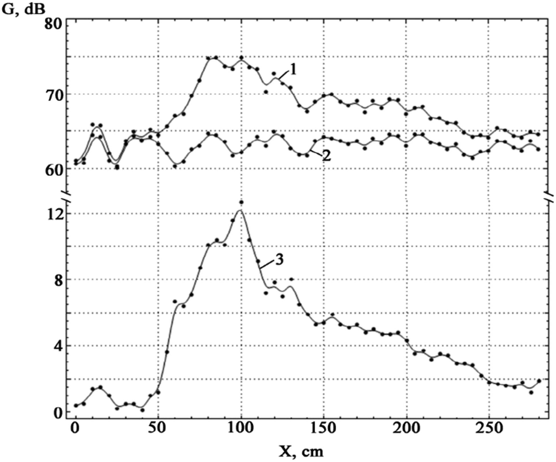
By adjusting the position of the FZP along the main axis from the edge of the paraboloid, we achieve an increased distance between the FZP and the oscillation source, up to the value f 3 = 2F 3. This allows us to determine the zone of maximum oscillation amplitude that has passed through the FZP. The outcomes of this experiment are presented in Figure 10. In this particular trial, taking the noise component into account, the highest oscillation amplitude reached 79.5 dB, with a variation of ΔA = 1.59 dB and an error margin of ε = 2.36%. This value corresponds to the 2.45 m mark. However, when comparing the experimental results with theoretical calculations, a certain discrepancy becomes apparent. The first focus appears somewhat indistinct. A noticeable rise in amplitude occurs not at a value of 1.2 m, but rather at 1.5 m. In the region of the second focus, there is a sharp escalation in oscillation amplitude, which continues to grow and culminates at 2.45 m. Subsequently, the amplitude decreases, resulting in a cone-shaped divergence of sound.
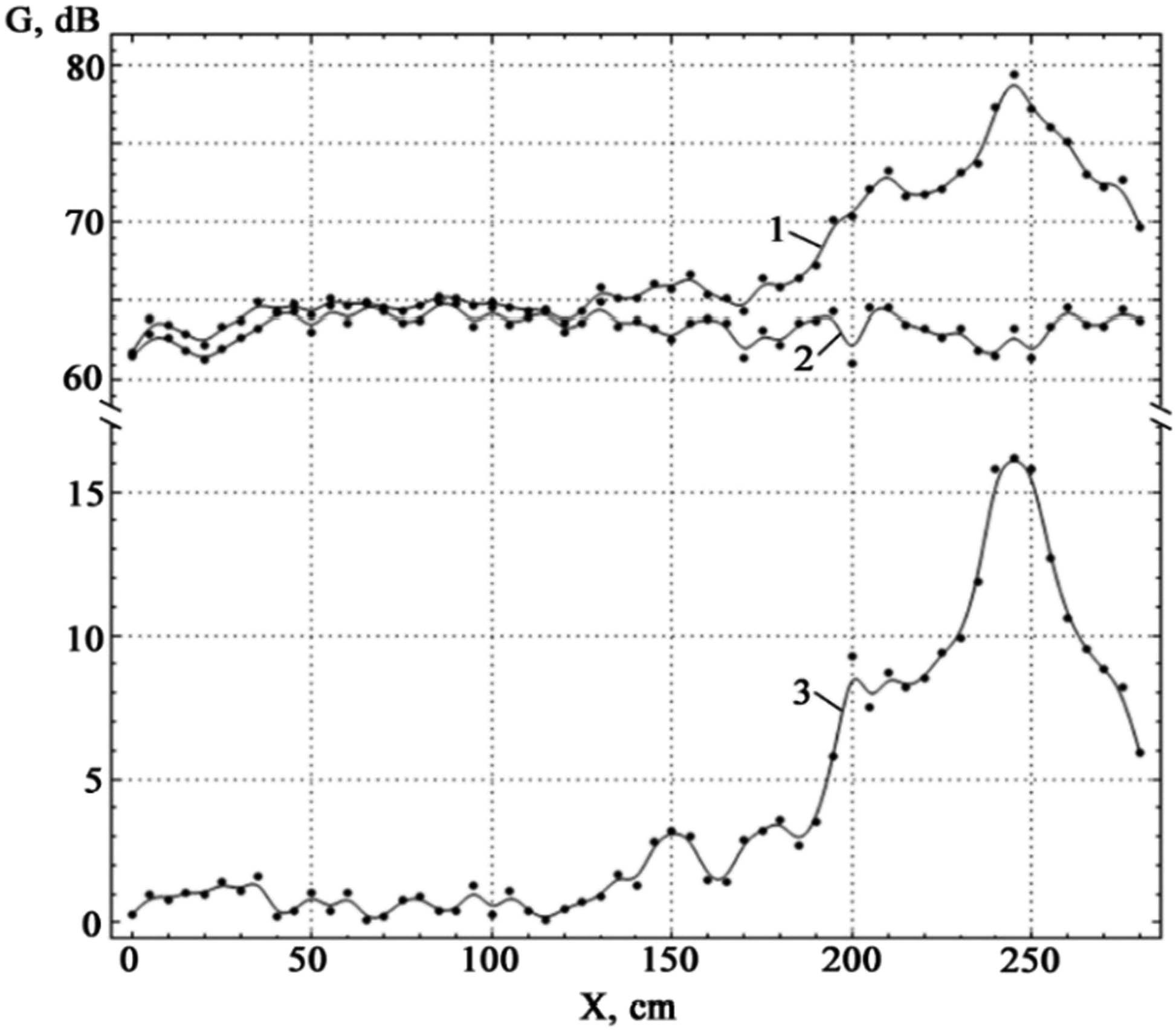
Experimental dependence of the amplitude of sound oscillations on the distance to the FZP (curve 1), noise values for different distances when the sound is turned on (curve 2), and pure sound amplification from the FZP (curve 3) for a frequency of 7,200 Hz.
To verify the relationship between the parameters of diffraction phenomena and the utilization of FZF when emitting source oscillations at different frequencies with the transmitter and receiver situated at a double focus, a series of analogous experiments were conducted, reducing the frequency relative to the initial 6,000 Hz by 20%, i.e., to a frequency of 4,800 Hz. For this frequency, the focal length value determined by formula (28) amounts to 0.8 m. The oscillation amplitude’s dependence on the distance to the FZP for a frequency of 4,800 Hz is depicted in Figure 11.
Experimental dependence of the amplitude of sound oscillations on the distance to the FZP (curve 1), noise values for different distances when the sound is turned on (curve 2), and pure sound amplification from the FZP (curve 3) for a frequency of 4,800 Hz.
The maximum oscillation amplitude, taking into account the noise component of 80.0 dB, was observed at a distance of 1.6 m.
The experimental dependence of the amplitude of sound oscillations on the distance to the FZP is depicted in Figure 12. Noteworthy is the frequency deviation from the baseline of 6,000 Hz by 50%. This led to a significant decrease in the maximum oscillation amplitude and the net amplification provided by the FZF. Therefore, a deviation from the base frequency of 6,000 Hz by 20% should be considered as the optimal condition.
Experimental dependence of the amplitude of sound vibrations on the distance to the FZP (curve 1), noise values for different distances when the sound is turned on (curve 2), and pure sound amplification from the FZP (curve 3) for a frequency of 3,000 Hz.
To organize the obtained results systematically, the measurement data and theoretical calculations regarding the positions of oscillation concentration at different source positions relative to the FZF and at various frequencies are presented in Table 3 and Figure 13.
Results of experimental and theoretical studies for determining oscillation concentration parameters
| Frequency (Hz) | 3,000 | 4,800 | 6,000 | 7,200 | |
|---|---|---|---|---|---|
| Wave length (m) | 0.114 | 0.071 | 0.057 | 0.047 | |
| Focal length of the ZPF (m) | Theory | 0.497 | 0.798 | 0.994 | 1.206 |
| Double focus of FZP (point of maximum amplitude) (m) | Theory | 0.994 | 1.596 | 1.988 | 2.412 |
| Experiment | 1.0 | 1.6 | 2.0 | 2.45 | |
| Maximum amplitude with noise (dB) | 74.9 | 80.0 | 86.1 | 79.5 | |
| Net Gain of FZF (dB) | 12.7 | 16.3 | 21.3 | 16.2 | |
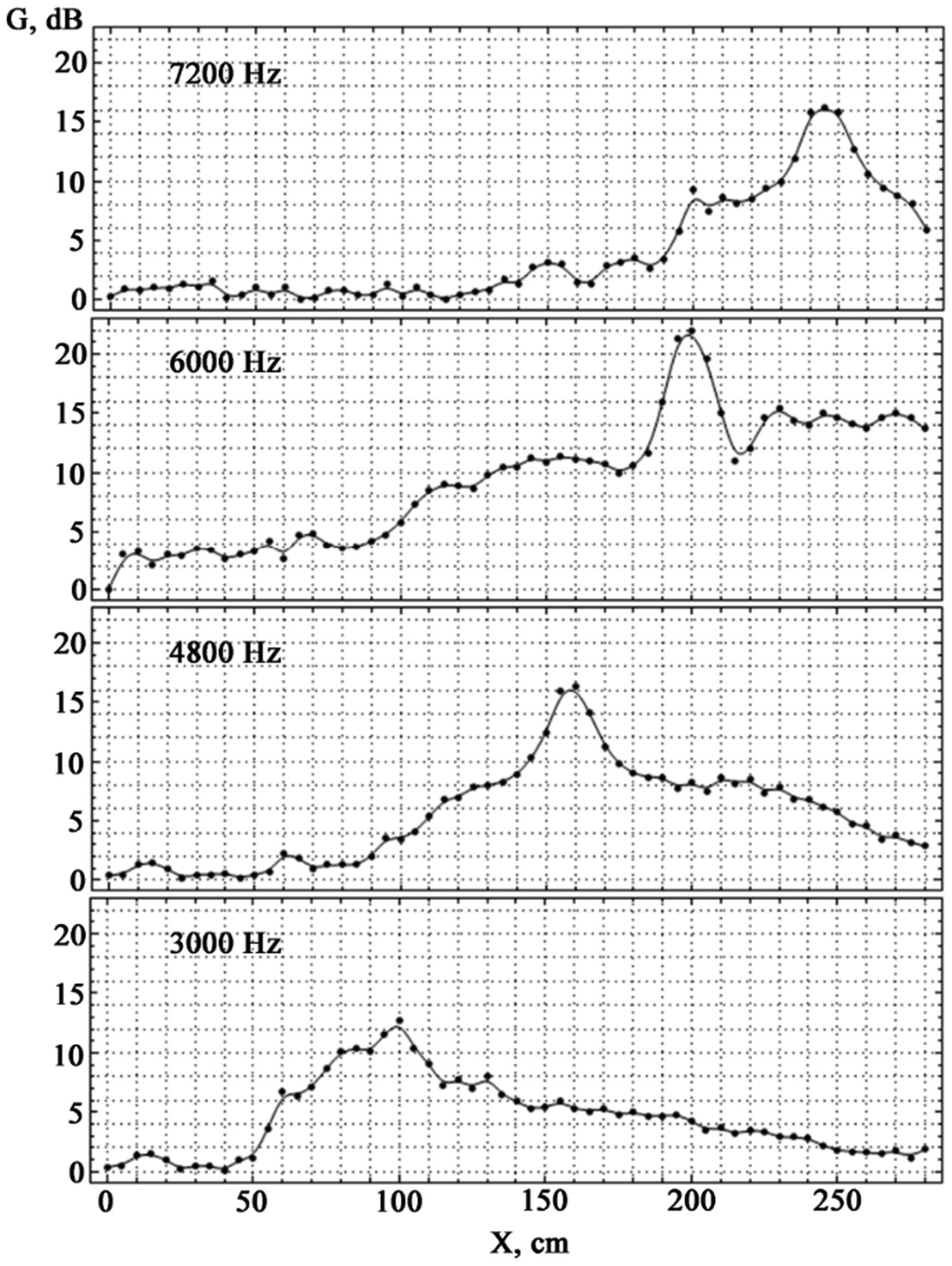
Experimental dependence of pure sound amplification on FZF for different sound frequencies.
For a clearer determination of the values Amax in Table 3, spline interpolation was employed.
Analysis of the theoretical calculation results presented in Table 3 reveals an inversely proportional relationship between the FZF focus and the wavelength. It has been observed that reducing the frequency by several times results in a corresponding decrease in the focal length. To establish general patterns of oscillation concentration for different frequencies using a single FZF, the experimentally obtained graphs in Figures 9–12 were rescaled on the same axes and arranged in ascending order of the analyzed noise oscillation frequencies (Figure 13). Connecting the corresponding foci of these dependencies with dotted lines enables us to predict how the positions of amplitudes passing through noise components of other frequencies within this range might change.
The primary objective of this work was to explore the potential of using the FZF calculated for a specific base frequency with other frequencies and to determine the frequency range in which the FZF retains its aperture properties. Estimating the size of focal spots in the oscillation concentration zone based on auditory perception and evaluation of the observed effect remains subjective.
Given the significant variability of experimental data in global practice for assessing and mitigating noise components from moving transportation sources, and the fundamental impossibility of isolating specific fixed frequencies from the entire noise spectrum, there are no standards or well-established experimental methodologies for determining the size of focal spots in the noise concentration zone.
Some experience in evaluating laser radiation and focusing light fields can be found in works on computer optics [30,31,32]. Though the application of sound vibrations might seem somewhat artificial, a qualitative trend can still be discerned.
As evident from the analysis of Figure 13, the longitudinal distribution of field intensity at the axial position of the radiation source exhibits maxima, the positions of which along the optical axis are wavelength-dependent. The peak widths were determined by studying the intensity profile of oscillations across the width of the maximum amplitude peak at half of its height [30]. The measurements indicated that the peak width at half maximum was 32 cm for 6,000 Hz, 60 cm for 7,200 Hz, 64 cm for 4,800 Hz, and 80 cm for 3,000 Hz. Deviating from the fundamental frequency of 6,000 Hz leads to increased peak width with decreasing maximum amplitude.
Since the focal length of the FZP is influenced by the wavelength, being inversely proportional to it, the FZF’s focal length measured from the geometric center will be greater for shorter wavelengths and higher frequencies of the incident sound (Figure 14).
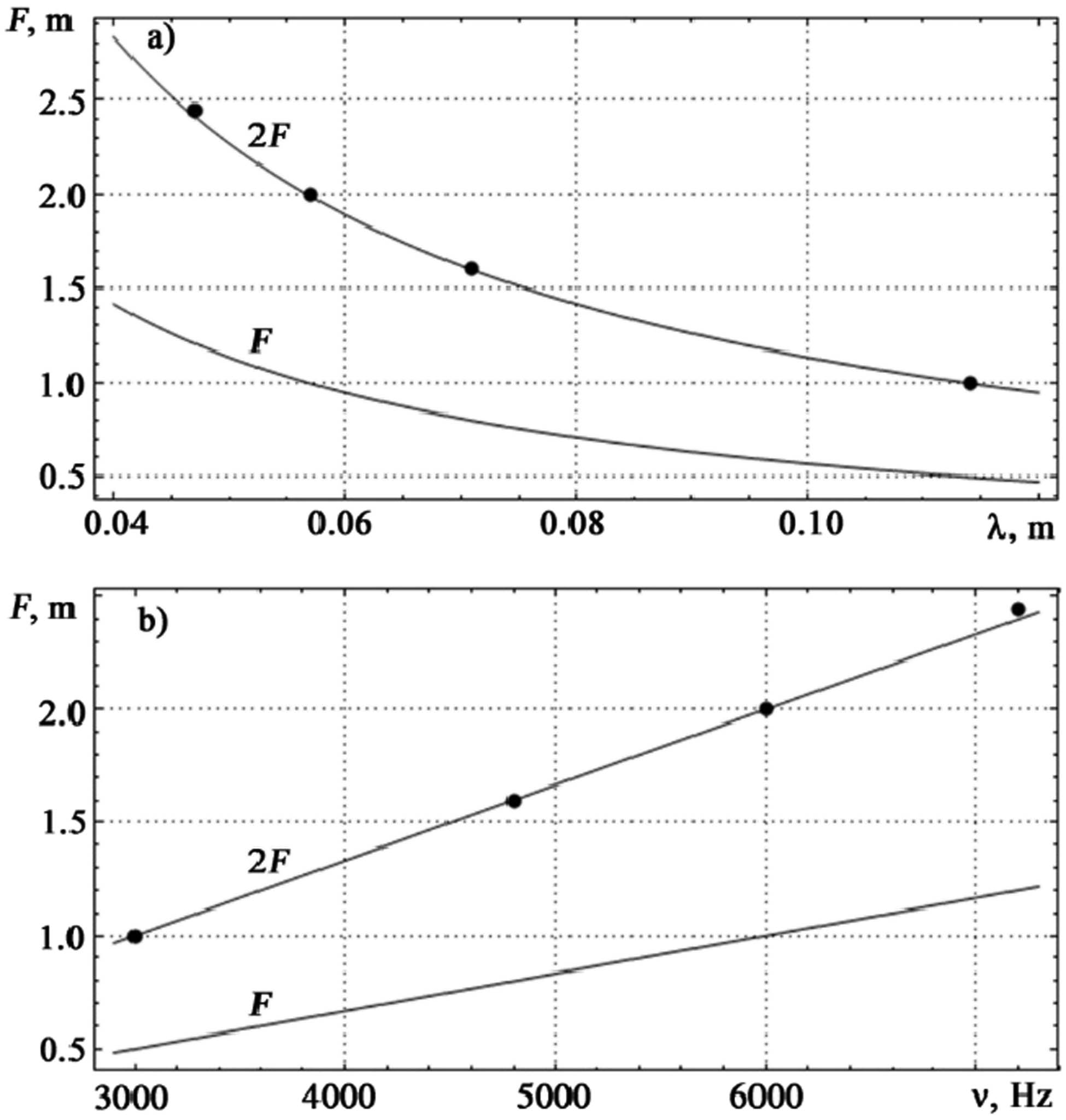
Theoretical (lines) and experimental (dots) dependencies of the focal and double focal lengths of the FZP on (a) the wavelength and (b) frequency of sound vibrations.
Analyzing the observed trends in conjunction with the Amax values provided in Table 3 and their corresponding positions for different frequencies enables us to draw a comprehensive conclusion about the viability of employing the FZP, initially calculated for a frequency of 6,000 Hz, for frequencies of 4,800 and 7,200 Hz – representing deviations of ±20%.
6 Conclusions
An active sound absorption system near highways is founded on the segregation of sound waves into incident and reflected components, adjusting reflections to desired levels, and controlling the directionality of transmitted vibrations. Vibrational concentration of waves passing through noise barriers is achieved through the implementation of diffraction effects in the Fraunhofer zones using acoustic FZPs, with the noise source positioned at the focus of the FZP.
Calculations of the resultant amplitude of oscillations passing through an axisymmetric acoustic FZP at points of wave concentration from both point and extended oscillation sources, along with the outer radii of the annular Fresnel zones, reveal an inversely proportional relationship between focal length and wavelength. Experimental investigations conducted for axial and off-axis receiver positions in relation to the point source of oscillations have demonstrated that the longitudinal intensity distribution of the field for axial radiation source positioning exhibits maxima. These maxima’s positions on the optical axis are wavelength-dependent – a unique aspect absent in refractive lenses that possess minimal chromatic aberration. This feature serves as an advantage for diffractive lenses, broadening their practical utility. The applicability of the thin lens formula for oscillation focusing after the FZP has been substantiated.
The experimental confirmation of the feasibility of using the FZP for passing sounds of different wavelengths has been established. It has been determined that experiments utilizing the same FZP can be conducted for diverse wavelengths within a range of ±20% relative changes, while adhering to diffraction conditions. In this context, the oscillation concentration remains intact, though the point of concentration shifts position.
Theoretical and empirical investigations have been undertaken to ensure the control of noise absorption from sound vibrations through the transformation of stochastic noise components produced by moving vehicles into a beam of parallel plane waves along the primary axis of the FZP. The possibility of replacing refractive lenses with diffractive ones has been verified. The noise protection effect is particularly noticeable within the acoustic shadow zone. Notably, the substitution of refractive acoustic energy concentrators with diffractive counterparts is technically beneficial, technologically straightforward, and economically sound.
Acknowledgments
The authors consider it their pleasant duty to note the participation in the staging part of the experiment of I.M. Pashko, a teacher of the Kherson Physico-Technical Lyceum, and A.D. Rakoma, a student.
-
Funding information: This publication was written at the Technical University of Liberec with the support of the Institutional Endowment for the Long-Term Conceptual Development of Research Institutes, as provided by the Ministry of Education, Youth, and Sports of the Czech Republic in the year 2023.
-
Author contributions: All authors have accepted responsibility for the entire content of this manuscript and approved its submission.
-
Conflict of interest: The authors state no conflict of interest.
References
[1] Wehr R, Conter M, Haider M, Gasparoni S. Far-field measurements of the acoustic properties of noise barriers. Proceedings – 9th European Conference on Noise Control; 2012 Jun 10-13; Prague, Czech Republic. European Acoustics Association, 2012. p. 1320–3.Search in Google Scholar
[2] Pazos DFP. Characterization of the sound absorption of corrugated noise barriers. 18th International Congress on Sound and Vibration; 2011 Jul 10-14; Rio de Janeiro, Brazil. International Institute of Acoustics and Vibration. 2012. p. 1889–96.Search in Google Scholar
[3] Bugaru M, Vasile O, Neagoe M. Recent developments of noise attenuation using acoustic barriers for a specific edge geometry. Computation. 2021;9(12):129.10.3390/computation9120129Search in Google Scholar
[4] Fuchs A, Wehr R, Conter M. Proposal for an in situ approval testing and quality assurance procedure for assessing sound reflection properties of noise barriers. 24th International Congress on Sound and Vibration; 2017 Jul 23-27; London, UK. International Institute of Acoustics and Vibration; 2017. p. 5811–17.Search in Google Scholar
[5] Jiang XP, Zhang TB, Jia J, Yue YF. Theoretical study on the acoustic field distribution of a rectangular transducer in attenuated media. Proceedings of SPIE – The International Society for Optical Engineering; 2020 Nov 20; Beijing, China. SPIE. 2020. id: 1156826.10.1117/12.2581299Search in Google Scholar
[6] Fuchs A, Wehr R, Conter M. Empirical study on the correlation between measurement methods under diffuse and direct sound field conditionsfor determining sound absorption and airborne sound insulation properties of noise barriers. Proceedings of INTER-NOISE 2021 - 2021 International Congress and Exposition of Noise Control Engineering; 2021 Aug 1-5; Virtual.Search in Google Scholar
[7] Xing G, Yang P, He L, Feng X. Spatial averaging effects of hydrophone on field characterization of planar transducer using Fresnel approximation. Ultrasonics. 2016;71:51–8.10.1016/j.ultras.2016.05.022Search in Google Scholar PubMed
[8] Levin BM. Analysis of antenna characteristics in a fresnel zone. DIPED-2008 - Proceedings of 13th International Seminar/Workshop on Direct and Inverse Problems of Electromagnetic and Acoustic Wave Theory; 2008 Sep 22-25; Tbilisi, Georgia. IEEE. 2008. p. 65–8.10.1109/DIPED.2008.4671805Search in Google Scholar
[9] Calvo DC, Thangawng AL, Nicholas M, Layman CN. Thin Fresnel zone plate lenses for underwater acoustics: Modeling and experiments. OCEANS 2015 - MTS/IEEE Washington; 2015 Oct 19-22; Washington DC, USA. IEEE 2016. p. 1–16.10.23919/OCEANS.2015.7401947Search in Google Scholar
[10] Guan Y, Zhao D, Low TS. Experimental evaluation on acoustic impedance and sound absorption performances of porous foams withadditives with Helmholtz number. Aerosp Sci Technol. 2021;119:107120.10.1016/j.ast.2021.107120Search in Google Scholar
[11] Suharno R, Farah DB, Achmad C, Tuasikal MA, Dhoni H. Fabrication of acoustic panel from composites of coconut husk waste powder and styrofoam resin and its soundabsorption performance. Mater Sci Forum 1029:73–9.10.4028/www.scientific.net/MSF.1029.73Search in Google Scholar
[12] Rouyer J, Poulesquen A, Frizon F. Viscoelastic monitoring of curing geopolymer by ultrasonic rheology. IEEE International Ultrasonics Symposium (IUS); 2013 Jul 21-25; Prague, Czech Republic. IEEE. 2014.10.1109/ULTSYM.2013.0483Search in Google Scholar
[13] Cruz RA, Correa CR, Diaz-Ramirez GA. Acoustic properties of concrete modified with an asphalt/styrene butadiene emulsion. J Physics: Conf Ser. 2019;1247(1):012036.10.1088/1742-6596/1247/1/012036Search in Google Scholar
[14] Fang Y, Zhang X, Zhou J. Experiments on reflection and transmission of acoustic porous metasurface with composite structure. Compos Struct. 2018;185:508–14.10.1016/j.compstruct.2017.11.054Search in Google Scholar
[15] Chen Y, Jiang N. Carbonized and Activated Non-wovens as High-Performance Acoustic Materials: Part I Noise Absorption. Text Res J. 2007;77(10):785–91.10.1177/0040517507080691Search in Google Scholar
[16] Lutgendorf D, De Roo F, Van Der Eerden F, Jean P, Ecotière D, Dutilleux G. Numerical simulation of the sound reflection effects of noise barriers in near and far field. Proceedings of Forum Acusticum 2011 Jun 27-Jul 1; Aalborg, Denmark. European Acoustics Association; 2011. p. 149–54.Search in Google Scholar
[17] Conter M, Wehr R. Comparison between laboratory and in-situ methods for measuring sound absorption properties of noise barriers. EuroNoise 2015; 2015 May 31-Jun 3; Maastricht, The Netherlands. European Acoustics Association, 2015;52–6.Search in Google Scholar
[18] Reiter P, Wehr R, Ziegelwanger H, Conter M. Optimization of noise barrier reflection properties. Proceedings of the INTER-NOISE 2016 - 45th International Congress and Exposition on Noise Control Engineering: Towards a Quieter Future; 2016 Aug 21-24; Hamburg, Germany. German Acoustical Society, 2016, p. 4261–5.Search in Google Scholar
[19] Chen S, Lee WC, Wu TL. A balanced-to-balanced power divider with common-mode noise absorption. IEEE MTT-S International Microwave Symposium (IMS); 2016 May 22-27; San Francisco (CA), USA. IEEE; 2016. p. 1–4.10.1109/MWSYM.2016.7540282Search in Google Scholar
[20] Hong B, Yoon J, Jang K, Kim Y, Seo E. Apply double layer sound absorption system development and acoustic performance evaluation of low heightbarrier near railways. INTER-NOISE 2018 - 47th International Congress and Exposition on Noise Control Engineering: Impact of Noise Control Engineering; 2018 Aug 26-29; Chicago (IL), USA. International Institute of Noise Control Engineering, 2018.Search in Google Scholar
[21] Zhu H, Rajamani R, Stelson KA. Active control of acoustic reflection, absorption, and transmission using thin panel speakers. J Acoustical Soc Am. 2003;113(2):852–70.10.1121/1.1534834Search in Google Scholar PubMed
[22] Thorsson PJ, Wgren M. Macroscopic modeling of urban traffic noise influence of absorption and vehicle flow distribution. Appl Acoust. 2005;66(2):195–209.10.1016/j.apacoust.2004.07.013Search in Google Scholar
[23] Picaut J, Scouarnec D. Using acoustic diffusors to reduce noise in urban areas. Acta Acust United Acust. 2009;95(4):653–68.10.3813/AAA.918194Search in Google Scholar
[24] Vanlanduit S, Vanherzeele J, Guillaume P, De G. Sitter Absorption measurement of acoustic materials using a scanning laser Doppler vibrometer. J Acoust Soc Am. 2005;117(3I):1168–72.10.1121/1.1859233Search in Google Scholar
[25] Fenlon FH. On the performance of a dual frequency parametric source via matched asymptotic solutions of Burgers’ equation. J Acoust Soc Am. 1987;55(1):35–46.10.1121/1.1919473Search in Google Scholar
[26] Louda P, Sharko A, Stepanchikov D, Sharko A. Experimental and theoretical study of plastic deformation of epoxy coatings on metal substrates using the acoustic emission method. Materials. 2022;15(11):3791.10.3390/ma15113791Search in Google Scholar PubMed PubMed Central
[27] Louda P, Sharko O, Stepanchikov D, Sharko A. Features of the application of the principal component method to the study of acoustic emission signals under loading of multilayer structures. In: Babichev S, Lytvinenko V, editors. Lecture Notes on Data Engineering and Communications Technologies. Vol. 149. Cham, Switzerland: Springer; 2022. p. 462–87.10.1007/978-3-031-16203-9_27Search in Google Scholar
[28] Louda P, Marasanov V, Sharko A, Stepanchikov D, Sharko A. The theory of similarity and analysis of dimensions for determining the state of operation of structures under difficult loading conditions. Materials. 2022;15(3):1191.10.3390/ma15031191Search in Google Scholar PubMed PubMed Central
[29] Louda P, Sharko A, Stepanchikov D. An acoustic emission method for assessing the degree of degradation of mechanical properties and residual life of metal structures under complex dynamic deformation stresses. Materials. 2021;14(9):2090.10.3390/ma14092090Search in Google Scholar PubMed PubMed Central
[30] Savelyeva AA, Kozlova ES. Comparison of the shapes of focal spots in terms of intensity and energy flux for a high-aperture zone plate and a spiral zone plate. Comput Opt. 2022;46(4):531–6. 10.18287/2412-6179-co934.Search in Google Scholar
[31] Kotlyar VV, Stafeev SS, Kovalev AA. Sharp focusing of a light field with a polarization and phase singularity of arbitrary order. Comput Opt. 2019;43(3):337–46. 10/18287/2412-6179-2019-43-3-337-346.Search in Google Scholar
[32] Doskolovich LL, Bezus EA, Bykov DA, Skidanov LL. Calculation of a diffractive lens with a fixed focus position at several given wavelengths. Comput Opt. 2019;43(6):946–55. 10.18287/2412-6179-2019-43-6-946-955.Search in Google Scholar
© 2024 the author(s), published by De Gruyter
This work is licensed under the Creative Commons Attribution 4.0 International License.
Articles in the same Issue
- Regular Articles
- Low-frequency cabin noise of rapid transit trains
- Utilizing the phenomenon of diffraction for noise protection of roadside objects
- Benchmarking the aircraft noise mapping package developed for a unified urban environmental modelling tool
- Acoustical analysis and optimization design of the hair dryers
- Methodologies for the prediction of future aircraft noise level
- Basics of meteorology for outdoor sound propagation and related modelling issues
- Predictive noise annoyance and noise-induced health effects models for road traffic noise in NCT of Delhi, India
- Modeling and mapping of traffic noise pollution by ArcGIS and TNM2.5 techniques
- A novel method for constructing large-scale industrial noise maps based on open source data
- Understanding perceived tranquillity in urban Woonerf streets: case studies in two Dutch cities
- Review Article
- A comprehensive review of noise pollution monitoring studies at bus transit terminals
- Rapid Communication
- The Environment (Air Quality and Soundscapes) (Wales) Act 2024
- Erratum
- Erratum to “Comparing pre- and post-pandemic greenhouse gas and noise emissions from road traffic in Rome (Italy): a multi-step approach”
- Special Issue: Latest Advances in Soundscape - Part II
- Soundscape maps of pleasantness in a university campus by crowd-sourced measurements interpolation
- Conscious walk assessment for the joint evaluation of the soundscape, air quality, biodiversity, and comfort in Barcelona
- A framework to characterize and classify soundscape design practices based on grounded theory
- Perceived quality of a nighttime hospital soundscape
- Relating 2D isovists to audiovisual assessments of two urban spaces in a neighbourhood
- Special Issue: Strategic noise mapping in the CNOSSOS-EU era - Part I
- Analysis of road traffic noise in an urban area in Croatia using different noise prediction models
- Citizens’ exposure to predominant noise sources in agglomerations