Ultra-secure optical encryption based on tightly focused perfect optical vortex beams
-
Qingshuai Yang


Abstract
Light’s orbital angular momentum (OAM) with inherent mode orthogonality has been suggested as a new way to the optical encryption. However, the dependence of annular intensity profiles on the topological charge complicates nanoscale light–matter interactions and hampers the ultra-secure encryption application. In this paper, we demonstrate ultra-secure image encryption by tightly focusing perfect optical vortex (POV) beams with controllable annular intensity profiles and OAM states. A simple scheme composed of single spatial light modulator to implement Fourier transform of an ideal Bessel mode with both amplitude and phase modulations is proposed to generate radius-controllable POV in tightly focused beams. Such focused POV beams with identical intensity profiles but varied local OAM density are applied to disorder-coupled gold nanorod aggregates to selectively excite electromagnetic hot spots for encoding information through photothermal deformation. As such, ultra-secure image encryption in OAM states of POV beams in combination with different polarizations can be achieved. Our results lay the ground for diverse nanophotonic applications harnessing the OAM division of POV beams.
1 Introduction
Recently, optical vortices have attracted significant research interests owing to the well-defined on-axis orbital angular momentum (OAM) they may carry [1]. A helical wavefront of exp(ilϕ) with multiple of 2π phase accumulation winding around the beam center denotes its characteristic properties [2]. This prominent feature has impinged diverse photonic applications including optical trapping [3], [4], [5], super-resolution imaging [6], lasing [7], optical communications [8, 9], and metasurface [10], [11], [12]. In particular, the inherent mode orthogonality of OAM states has been suggested as an excellent information carrier for multiplexing to boost the information capacity of both optical communications [13, 14], and holographic encryption [15], [16], [17]. However, the annular intensity profile and peak intensity vary as a function of topological charges of vortex beams. The interdependence complicates nanoscale light–matter interactions with varied both local intensity and OAM density and becomes problematic in applications that require to couple multiple OAM beams into fixed spatial modal distributions.
In this regard, the concept of perfect optical vortex (POV) whose annular intensity profiles of the generated beam are immune to the variation of topological charge has been introduced [18]. An idea POV beam can be treated as the Fourier transform (FT) of a Bessel beam. The general approaches to create such POV beams generally involve the superposition of an axicon phase function with a vortex phase, which has been implemented through metasurface elements [19], digital micromirror device [20], conical axicon [21], and liquid-crystal spatial light modulators (SLMs) [22, 23]. Unfortunately, these methods are only demonstrated effective in paraxial conditions. The presence of an axicon phase leads to defocusing effect in the propagation axis and the shifted focal spot is often understated with degraded both intensity profiles and ring radius, especially in applications where tightly focused POV beams are on-demand.
In this paper, we demonstrate POV with controlled annular radius and peak intensities in tightly focused conditions. The complex field of Fourier transfer of the focused POV expressed as a diffraction-limited annular ring intensity profile superposed with a vortex phase is implemented through a single SLM approach. It allows the generated POV beam with controlled annular radius and arbitrary local OAM densities in the focal plane. As a proof-of-principle, such tightly focused POV beams are applied to gold nanorod aggregates for ultra-secure image encryption in both topological charges and polarizations through a selective photothermal deformation process.
2 Results and discussion
2.1 Theoretical and experimental verification of tightly focused POV
The complex amplitude expression of an ideal POV with topological charge
where
where
where
For the field distribution in Eq. (3), its FT in polar coordinates is given by [22]:
where
where FT{·} represent the FT;
where
As can be seen from Eq. (6), the topological charge will not affect the amplitude distribution, which satisfies the definition of POV. Therefore, we can generate a tightly focused POV by implementing FT of an ideal Bessel mode with both amplitude and phase modulations according to Eq. (4). Now, the complex optical field can be expressed as
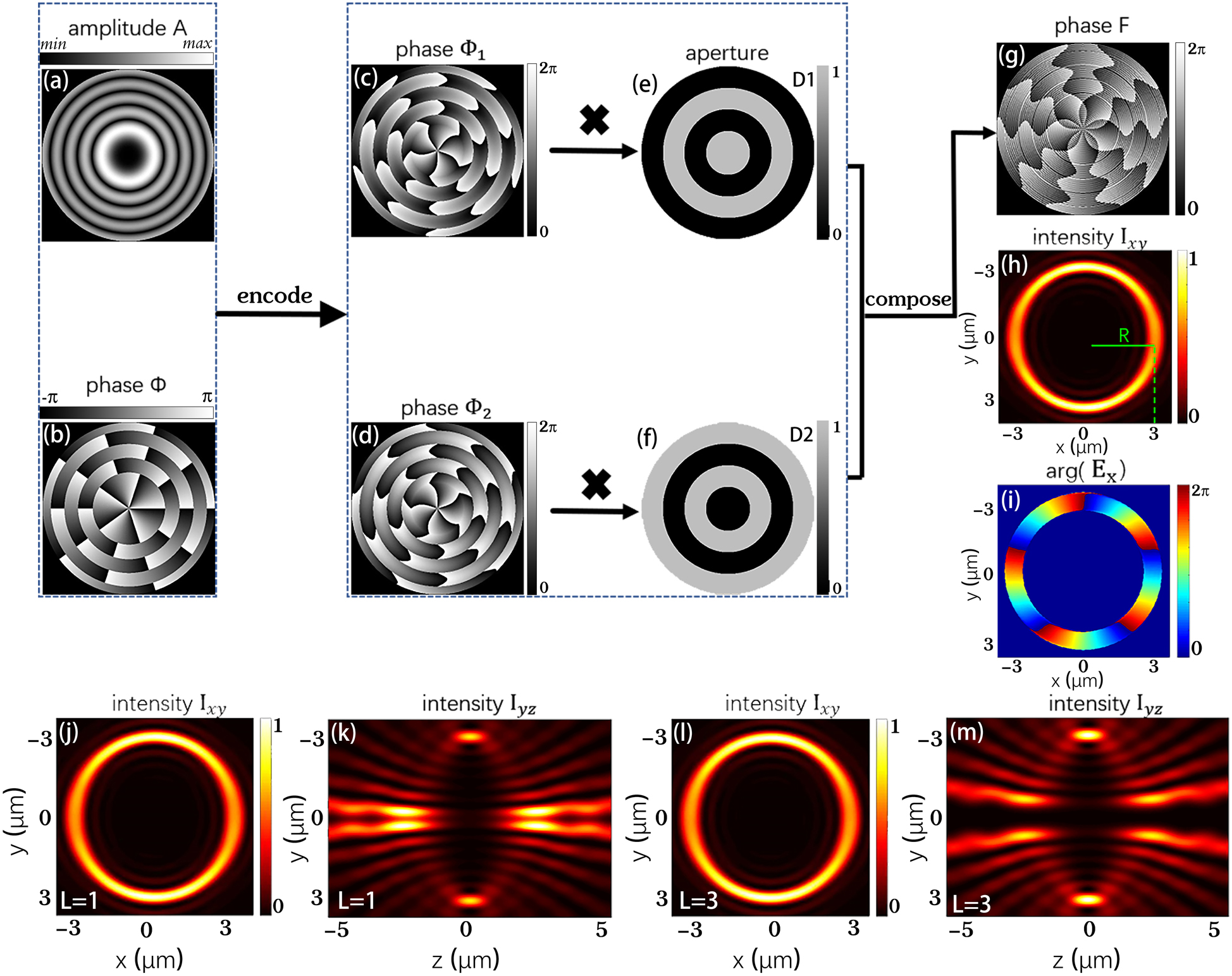
Schematic diagram of the calculation process of perfect vortex phase patterns. (a) Amplitude and (b) phase distributions of the complex field in Eq. (4). (c) and (d) Two phase-only distributions correspond to Eq. (7). (e) and (f) A pair of complementary ring-shaped apertures. (g) The final synthesized phase distribution. (h) and (i) The intensity distribution in the
To simplify the experimental configuration, we can use a phase-only SLM to generate complex amplitude modulations, in which amplitude and phase are modulated simultaneously. First, we rewrite the complex field expression as the superposition of two phase-only modulations:
The corresponding calculation results of two phase-only distributions are displayed in Figure 1(c) and (d). Then, in order to use a phase pattern to generate the complex field, the two kinds of different phase information must be superimposed on a single pattern. Here, we designed a pair of complementary ring-shaped apertures,
The superimposed phase is displayed in Figure 1(g). Based on the synthetic phase, we can realize the complex optical field. Finally, a POV is created in the tightly focus system.
Figure 1(h) shows the intensity distribution in the focus plane of a high NA objective lens when the incident optical field is modulated by phase F. It can be seen that the intensity profile of the optical field is a ring shape, and the radius is consistent with the theoretically designed value, indicating that the radius is controllable by this method. Simultaneously, its phase distribution of Ex exhibits 5-fold of 2π phase accumulation winding around the beam center, coinciding with theoretically designed topological charge
To experimentally verify the tightly focused POV, we conducted an interference experiment with our homemade setup. Figure 2(a) and (c) shows the POVs generated on the focal plane of the objective lens, with various topological charges (
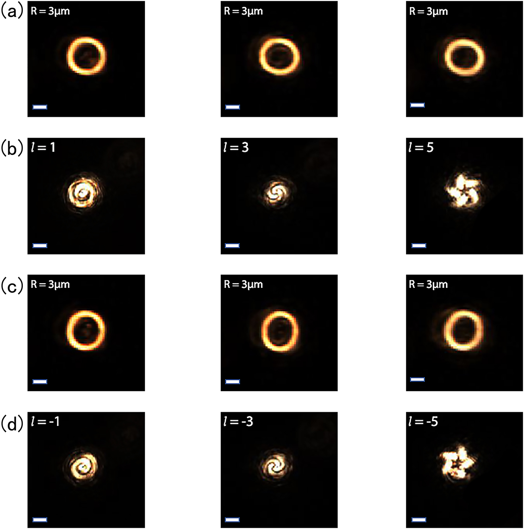
Intensity distributions and corresponding interference patterns of POVs with different topological charges. (a) and (c) Intensity patterns of POV with different topological charges on the focal plane (Z = 0). (b) and (d) The corresponding coaxial interference patterns. Scale bar: 3 μm.
2.2 Simulation and experimental results of optical storage
When these tightly focused POV interact with gold nanorod aggregates, the focal polarization distributions play an important role. It has been shown that the vortex beam can introduce OAM-dependent spatial rotations of the focal polarization ellipses and hence synthetic helical dichroism (HD) in individual gold nanorods [27]. Based on the vectorial diffraction integral theory, we can calculate and analyze the electric field components,
where
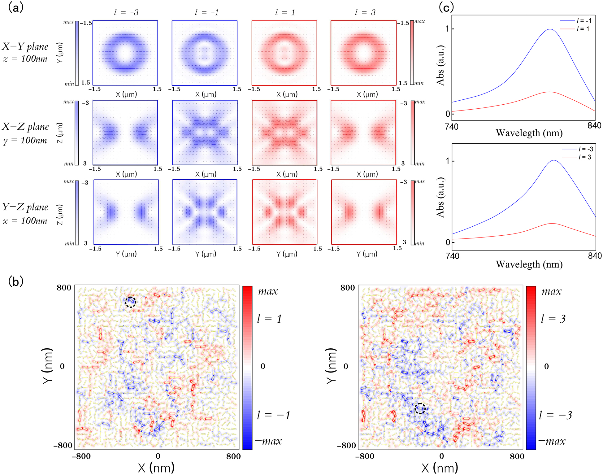
Synthetic helical dichroism by focused POVs. (a) The polarization ellipse and normalized intensity distributions of the
In order to provide an intuitive illustration, we used a simplified model to qualitatively evaluate the response of a disordered gold nanorod assembly under the excitation of a tightly focused POV [27, 29]. The simplified model consists of 961 gold nanorods, which are 50 nm in length and 12 nm in diameter. The gold nanorod array contains 31 × 31 randomly oriented gold nanorods whose centers form a square array with a lattice constant of 50 nm. The electric field distribution of gold nanorods can be calculated by the finite-difference time-domain (FDTD) method and the non-uniform grid with the maximum mesh step of 4 nm as well as perfectly matched layer boundary conditions are used in the numerical simulation. By calculating the intensity distribution generated by the interaction between the source which has been imported into the POV’s electric field distribution and the disordered gold nanorods model, we can intuitively see the excitation of localized electromagnetic hot spots by POV with variant topological charges, as shown in Figure 3(b). It is clearly seen that the recording beam with different topological charges can excite different hot spots constituted by different gold nanorods denoted by red and blue color. Then, the GNRs near the hotspots exhibiting strong difference in excitation strength in the disordered arrays were selected to unveal the linear absorption differences to the incident POV beams of opposite topological charges, which is shown in Figure 3(c). As a result of the non-trivial difference in excitation strengths, synthetic HD spontaneously emerges in which the GNR exhibits different linear absorptions for OAM beams [27]. When raising the beam power, the gold nanorods nearby these hot spots can be selectively photothermally reshaped to provide a mechanism for optical encryption in the OAM states of the POV.
To experimentally demonstrate ultra-secure optical image encryption by tightly focused POV, we prepared samples of gold nanorod aggregates. Gold nanorods with an initial optical density of 90 were mixed with 10 wt% poly(vinyl alcohol) polymer and self-dried at room temperature. In Figure 4(a), we show eight images encrypted at the same spatial region by the eight types of combination with polarization and topological charge, which have been marked in the corresponding positions. Each image consists of 30 by 30 pixels with a pixel separation of 1.5
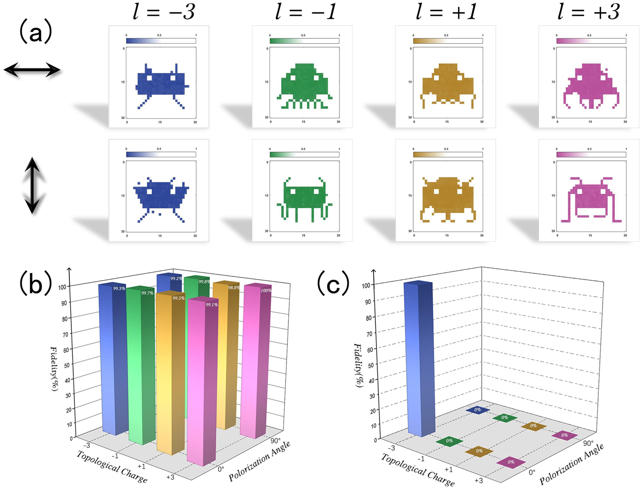
Ultra-secure optical encryption and encoding. (a) Schematic of the optical image encryption in a spatial region (45 × 45 μm2 with 30 × 30 pixels). The eight images are the retrieved results using eight different polarization and topological charge combinations, which are outlined in (b). The fidelity of these eight optically encrypted images in (a). (c) Analysis of fidelity of retrieved images using different combination of polarizations and topological charges.
Furthermore, we used a POV beam with topological charge
3 Conclusions
In summary, we propose a novel method to generate POV in the focal plane of tightly focused systems and we can control the radius and the topological charge based on a phase-only formula. Based on the complex expression of the FT of the ideal Bessel beam, we use a single phase-only SLM to achieve a complex field and focus this field onto the focal plane where the created POV is used to encryption. The image encryption has been demonstrated through the interaction between focused POV and disorder-coupled gold nanorod. Additionally, this novel approach can be used to generate other types of POV with different shape of the intensity distribution, such as elliptic POV [32, 33], fractional POV [34]. In theory, the physical dimension of OAM has boundless orthogonal states. It is anticipated that the combination of OAM and other physical dimensions can further increase the storage capacity of optical memory technology. We envision its huge potentials of application of this degree of freedom in different fields, such as multiplexed data storage, optical communication, and quantum entanglement, etc.
Funding source: Guangdong Provincial Innovation and Entrepreneurship Project
Award Identifier / Grant number: 2016ZT06D081
Award Identifier / Grant number: 2019ZT08X340
Funding source: National Natural Science Foundation of China
Award Identifier / Grant number: 61522504
Award Identifier / Grant number: 61875073
Award Identifier / Grant number: 61975066
Award Identifier / Grant number: 62174073
Award Identifier / Grant number: 91750110
Funding source: Research and Development Plan in Key Areas of Guangdong Province
Award Identifier / Grant number: 2018B010114002
Funding source: Pearl River Nova Program of Guangzhou
Award Identifier / Grant number: 201806010040
-
Author contribution: X.L. conceived the idea. Q.Y. performed the theoretical study. Q.Y. conducted the experiments with the help of Z.X., M.Z., X.O., Y.X., Y.C. and X.L. Y.X. and X.L. analysed the data. Q.Y. and X.L. wrote the manuscript with input from all the authors. X.L. supervised this project.
-
Research funding: National Natural Science Foundation of China (NSFC)(61522504 and 91750110), the Guangdong Provincial Innovation and Entrepreneurship Project (Grant 2016ZT06D081 and 2019ZT08X340), the Research and Development Plan in Key Areas of Guangdong Province (2018B010114002), the Pearl River Nova Program of Guangzhou (No. 201806010040), National Natural Science Foundation of China (NSFC)(61975066), National Natural Science Foundation of China (NSFC)(61875073), National Natural Science Foundation of China (NSFC)(62174073).
-
Conflict of interest statement: The authors declare no conflicts of interest regarding this article.
References
[1] A. M. Yao and M. J. Padgett, “Orbital angular momentum: origins, behavior and applications,” Adv. Opt. Photon., vol. 3, pp. 161–204, 2011, https://doi.org/10.1364/aop.3.000161.Suche in Google Scholar
[2] Y. Shen, X. Wang, Z. Xie, et al.., “Optical vortices 30 years on: OAM manipulation from topological charge to multiple singularities,” Light Sci. Appl., vol. 8, pp. 1–29, 2019, https://doi.org/10.1038/s41377-019-0194-2.Suche in Google Scholar PubMed PubMed Central
[3] M. Padgett and R. Bowman, “Tweezers with a twist,” Nat. Photonics, vol. 5, pp. 343–348, 2011, https://doi.org/10.1038/nphoton.2011.81.Suche in Google Scholar
[4] S. C. Chapin, V. Germain, and E. R. Dufresne, “Automated trapping, assembly, and sorting with holographic optical tweezers,” Opt. Express, vol. 14, pp. 13095–13100, 2006, https://doi.org/10.1364/oe.14.013095.Suche in Google Scholar PubMed PubMed Central
[5] M. Dienerowitz, M. Mazilu, and K. Dholakia, “Optical manipulation of nanoparticles: a review,” J. Nanophotonics, vol. 2, p. 021875, 2008, https://doi.org/10.1117/1.2992045.Suche in Google Scholar
[6] F. Tamburini, G. Anzolin, G. Umbriaco, A. Bianchini, and C. Barbieri, “Overcoming the Rayleigh criterion limit with optical vortices,” Phys. Rev. Lett., vol. 97, p. 163903, 2006, https://doi.org/10.1103/physrevlett.97.163903.Suche in Google Scholar
[7] H. Li, D. B. Phillips, X. Wang, et al.., “Orbital angular momentum vertical-cavity surface-emitting lasers,” Optica, vol. 2, pp. 547–552, 2015, https://doi.org/10.1364/optica.2.000547.Suche in Google Scholar
[8] J. T. Barreiro, T. C. Wei, and P. G. Kwiat, “Beating the channel capacity limit for linear photonic superdense coding,” Nat. Phys., vol. 4, pp. 282–286, 2008, https://doi.org/10.1038/nphys919.Suche in Google Scholar
[9] H. Ren, X. Li, Q. Zhang, and M. J. S. Gu, “On-chip noninterference angular momentum multiplexing of broadband light,” Science, vol. 352, pp. 805–809, 2016, https://doi.org/10.1126/science.aaf1112.Suche in Google Scholar PubMed
[10] H. Ren, G. Briere, X. Fang, et al.. “Metasurface orbital angular momentum holography,” Nat. Commun. vol. 10, pp. 1–8, 2019, https://doi.org/10.1038/s41467-019-11030-1.Suche in Google Scholar PubMed PubMed Central
[11] H. Ren, X. Fang, J. Jang, J. Bürger, J. Rho, and S. A. Maier. “Complex-amplitude metasurface-based orbital angular momentum holography in momentum space,” Nat. Nanotechnol. vol. 15, pp. 948-955, 2020, https://doi.org/10.1038/s41565-020-0768-4.Suche in Google Scholar PubMed
[12] X. Shan, Z. Li, L. Deng, and Q. Dai. “Continuous amplitude-modulated meta-fork gratings with zero-order extinction,” Opt. Lett. vol. 45, pp. 1902–1905, 2020, https://doi.org/10.1364/ol.387665.Suche in Google Scholar
[13] J. Wang, J. Yang, I. M. Fazal, et al.., “Terabit free-space data transmission employing orbital angular momentum multiplexing,” Nat. Photonics, vol. 6, pp. 488–496, 2012, https://doi.org/10.1038/nphoton.2012.138.Suche in Google Scholar
[14] W. Shao, S. Huang, X. Liu, and M. Chen, “Free-space optical communication with perfect optical vortex beams multiplexing,” Opt Commun., vol. 427, pp. 545–550, 2018, https://doi.org/10.1016/j.optcom.2018.06.079.Suche in Google Scholar
[15] X. Fang, H. Ren, and M. Gu, “Orbital angular momentum holography for high-security encryption,” Nat. Photonics, vol. 14, pp. 102–108, 2020, https://doi.org/10.1038/s41566-019-0560-x.Suche in Google Scholar
[16] H. Zhou, B. Sain, Y. Wang, et al.., “Polarization-encrypted orbital angular momentum multiplexed metasurface holography,” ACS Nano, vol. 14, pp. 5553–5559, 2020, https://doi.org/10.1021/acsnano.9b09814.Suche in Google Scholar PubMed PubMed Central
[17] H. Gao, X. Fan, W. Xiong, and M. Hong, “Recent advances in optical dynamic meta-holography,” Opto-Electron. Adv., vol. 4, p. 210030, 2021, https://doi.org/10.29026/oea.2021.210030.Suche in Google Scholar
[18] A. S. Ostrovsky, C. Rickenstorff-Parrao, and V. Arrizón, “Generation of the “perfect” optical vortex using a liquid-crystal spatial light modulator,” Opt. Lett., vol. 38, pp. 534–536, 2013, https://doi.org/10.1364/ol.38.000534.Suche in Google Scholar PubMed
[19] Y. Bao, J. Ni, and C. W. Qiu, “A minimalist single‐layer metasurface for arbitrary and full control of vector vortex beams,” Adv. Mater., vol. 32, p. 1905659, 2020, https://doi.org/10.1002/adma.201905659.Suche in Google Scholar PubMed
[20] Y. Chen, Z. Fang, Y. Ren, L. Gong, and R. Lu, “Generation and characterization of a perfect vortex beam with a large topological charge through a digital micromirror device,” Appl. Opt., vol. 54, pp. 8030–8035, 2015, https://doi.org/10.1364/ao.54.008030.Suche in Google Scholar PubMed
[21] M. Chen, M. Mazilu, Y. Arita, E. M. Wright, and K. Dholakia, “Dynamics of microparticles trapped in a perfect vortex beam,” Opt. Lett., vol. 38, pp. 4919–4922, 2013, https://doi.org/10.1364/ol.38.004919.Suche in Google Scholar
[22] P. Vaity and L. Rusch, “Perfect vortex beam: Fourier transformation of a Bessel beam,” Opt. Lett., vol. 40, pp. 597–600, 2015, https://doi.org/10.1364/ol.40.000597.Suche in Google Scholar
[23] C. Zhang, C. Min, L. Du, and X. C. Yuan, “Perfect optical vortex enhanced surface plasmon excitation for plasmonic structured illumination microscopy imaging,” Appl. Phys. Lett., vol. 108, p. 201601, 2016, https://doi.org/10.1063/1.4948249.Suche in Google Scholar
[24] L. Gong, Y. Ren, G. Xue, et al.., “Generation of nondiffracting Bessel beam using digital micromirror device,” Appl. Opt., vol. 52, pp. 4566–4575, 2013, https://doi.org/10.1364/ao.52.004566.Suche in Google Scholar PubMed
[25] V. V. Kotlyar, A. A. Kovalev, and A. P. Porfirev, “Optimal phase element for generating a perfect optical vortex,” J. Opt. Soc. Am. A, vol. 33, pp. 2376–2384, 2016, https://doi.org/10.1364/josaa.33.002376.Suche in Google Scholar PubMed
[26] L. Zhu, R. Yang, D. Zhang, J. Yu, and J. Chen, “Dynamic three-dimensional multifocal spots in high numerical-aperture objectives,” Opt. Express, vol. 25, pp. 24756–24766, 2017, https://doi.org/10.1364/oe.25.024756.Suche in Google Scholar PubMed
[27] X. Ouyang, Y. Xu, M. Xian, et al.., “Synthetic helical dichroism for six-dimensional optical orbital angular momentum multiplexing,” Nat. Photonics, vol. 15, pp. 901–907, 2021, https://doi.org/10.1038/s41566-021-00880-1.Suche in Google Scholar
[28] M. Born and E. Wolf, Principles of Optics: in Electromagnetic Theory of Propagation, Interference and Diffraction of Light, New York, Cambridge University Press, 2000.10.1063/1.1325200Suche in Google Scholar
[29] Q. Dai, M. Ouyang, W. Yuan, et al.., “Encoding random hot spots of a volume gold nanorod assembly for ultralow energy memory,” Adv. Mater., vol. 29, p. 1701918, 2017, https://doi.org/10.1002/adma.201701918.Suche in Google Scholar PubMed
[30] X. Li, T. H. Lan, C. H. Tien, and M. Gu, “Three-dimensional orientation-unlimited polarization encryption by a single optically configured vectorial beam,” Nat. Commun., vol. 3, pp. 1–6, 2012, https://doi.org/10.1038/ncomms2006.Suche in Google Scholar PubMed PubMed Central
[31] Y. Zhang, J. Han, L. Shi, et al.., “Extremely polarized and efficient hot electron intraband luminescence from aluminum nanostructures for nonlinear optical encoding,” Laser Photon. Rev., vol. 15, p. 2000339, 2021, https://doi.org/10.1002/lpor.202000339.Suche in Google Scholar
[32] A. Kovalev, V. Kotlyar, and A. Porfirev, “A highly efficient element for generating elliptic perfect optical vortices,” Appl. Phys. Lett., vol. 110, p. 261102, 2017, https://doi.org/10.1063/1.4990394.Suche in Google Scholar
[33] L. Li, C. Chang, C. Yuan, et al.., “High efficiency generation of tunable ellipse perfect vector beams,” Photon. Res., vol. 6, pp. 1116–1123, 2018, https://doi.org/10.1364/prj.6.001116.Suche in Google Scholar
[34] F. Gu, L. Li, C. Chang, et al.., “Generation of fractional ellipse perfect vector beams,” Opt. Commun., vol. 443, pp. 44–47, 2019, https://doi.org/10.1016/j.optcom.2019.03.023.Suche in Google Scholar
Supplementary Material
The online version of this article offers supplementary material (https://doi.org/10.1515/nanoph-2021-0786).
© 2022 Qingshuai Yang et al., published by De Gruyter, Berlin/Boston
This work is licensed under the Creative Commons Attribution 4.0 International License.
Artikel in diesem Heft
- Frontmatter
- Reviews
- Photonic neuromorphic technologies in optical communications
- Photo-modulated optical and electrical properties of graphene
- Optical metasurfaces for generating and manipulating optical vortex beams
- Research Articles
- Photon coupling-induced spectrum envelope modulation in the coupled resonators from Vernier effect to harmonic Vernier effect
- Generation of high-uniformity and high-resolution Bessel beam arrays through all-dielectric metasurfaces
- Controlling and probing heat generation in an optical heater system
- Nonthermal laser ablation of high-efficiency semitransparent and aesthetic perovskite solar cells
- Plasmon-enhanced photoluminescence from MoS2 monolayer with topological insulator nanoparticle
- Polarization-controlled anisotropy in hybrid plasmonic nanoparticles
- Empirical formulation of broadband complex refractive index spectra of single-chirality carbon nanotube assembly
- Direct generation of entangled photon pairs in nonlinear optical waveguides
- A high-gain cladded waveguide amplifier on erbium doped thin-film lithium niobate fabricated using photolithography assisted chemo-mechanical etching
- High-performance near-infrared photodetectors based on gate-controlled graphene–germanium Schottky junction with split active junction
- Nonlinear thermal lensing of high repetition rate ultrafast laser light in plasmonic nano-colloids
- Ultra-secure optical encryption based on tightly focused perfect optical vortex beams