Guided-mode resonance on pedestal and half-buried high-contrast gratings for biosensing applications
-
Giovanni Finco

 ,
Mehri Ziaee Bideskan
,
Mehri Ziaee Bideskan

Abstract
Optical sensors typically provide compact, fast and precise means of performing quantitative measures for almost any kind of measurand that is usually probed electronically. High-contrast grating (HCG) resonators are known to manifest an extremely sharp and sensitive optical resonance and can constitute a highly suitable sensing platform. In this paper we present two advanced high-contrast grating designs improving the sensing performances of conventional implementations. These configurations, namely pedestal and half-buried HCGs, allow to enhance the shift of the photonic resonance while maintaining the spectral features of the standard configuration. First, the spectral feature of the HCGs was numerically optimized to express the sharpest possible resonance when the structure is immersed in serum. Second, the sensing properties of conventional and advanced HCG implementations were studied by modelling the biological entities to be sensed as a thin dielectric coating layer of increasing thickness. Pedestal HCGs were found to provide a ∼12% improvement in sensitivity and a six-fold improvement in resonance quality factor (Q-factor), while buried HCGs resulted in a ∼58% improvement in sensitivity at the expense of a slightly broader resonance. Such structures may serve as an improved sensitive biosensing platform for near-infrared spectroscopy.
1 Introduction
High-contrast grating (HCG) resonators are well-known and thoroughly studied dielectric nanostructures [1], [2], [3], [4], [5], [6], which have been used for many years in various applications from signal filtering [1], [2], [3, 7], [8], [9] to biosensing [4, 10], [11], [12], [13], [14], [15], [16], [17], [18], [19], [20]. A typical HCG consists of a one-dimensional periodic array of high-index structures (rectangular bars, tubes, or sinusoidal modulations of the refractive index), surrounded by a low-index medium. The physical behavior of such structure relies on the concept of leaky-mode resonances or guided-mode resonances (GMR). There also have been realizations of GMR in dielectric gratings placed on top of a dielectric slab waveguide [21]. We note that GMR-based devices are also known as resonant gratings waveguide structures [21] or resonant guided-mode filters (RGMFs) [1, 2].
The underlying meaning of leaky-mode resonances is that, should the structure be free of refractive index modulations, it would act a standard slab waveguide where the guided mode could not be excited by a plane wave impinging on the structure at normal incidence. However, with a perturbation of the dielectric constant, a transverse momentum could be generated, which causes the guided mode to couple to light waves in an ambient medium and to be excited by an incoming plane wave at normal incidence. Furthermore, HCGs are dramatically polarization dependent, as they can manifest extremely narrow or broadband near-unit reflection depending on design and polarization. The resonance originates from a strong coupling between grating modes and as such it is characterized by a Fano-shape [22].
Optical biosensing exploits the sensitivity of guided or resonant modes confined in photonic nanostructures to the environmental conditions [4, 10], [11], [12], [13, 16, 20]. Among several different approaches, refractometric sensing and wavelength interrogation [23] can be used where very small concentration variations of a specific analyte induce small changes of the local refractive index, resulting in the shift of resonance wavelength. Conventionally, plasmonic structures relying on either propagating or localized surface plasmons have been extensively used to detect biomarkers down to clinically-relevant concentrations [24], [25], [26]. Despite their high sensitivity, metallic platforms are characterized by large optical losses, which render accurate experiments harder to perform. On the other hand, high-Q resonance of dielectric HCG structures may provide higher accuracy in sensing and can be easily tuned to resonate in any wavelength range where materials can be approximated as lossless. Both one- and two-dimensional periodic dielectric nanostructures have been successfully used to perform the sensing tasks with encouraging results [14], [15], [16], [17], [18, 27], [28], [29], [30], [31], [32].
Here we present two advanced HCG designs based on GMR with different mechanisms to improve the sensitivity of such structures beyond the reported values for the conventional implementation. These new configurations will be referred to as pedestal and half-buried HCGs, respectively, as illustrated in Figure 1. Pedestal nanostructures are a quite novel approach that relies on the maximization of the sensing area and increased index contrast by partial etching of the substrate beneath the grating bars. This approach particularly suits HCGs as the resonance features heavily rely on a large index contrast. Plasmonic nanoparticles have been suspended on dielectric pedestals to improve the platform sensitivity with a configuration referred to as plasmonic nanomushrooms [33]. Furthermore, dielectric Mie resonators obtained by pedestalling silicon nanostructures have been reported [34], as well as silicon-on-insulator (SOI) suspended waveguide for mid-IR sensing [35]. In our case we apply pedestalling for long bars thus improving the figure-of-merit (FOM) by enhancing both the resonance redshift and the structure’s Q-factor. Up to date, there has not been any reported case of pedestal high-contrast gratings to the best of authors’ knowledge. The half-buried version of HCGs was inspired by [5], who propose a similar implementation to enhance the field interaction with metallic nanoantennas placed in between the grating bars for surface-enhanced Raman scattering (SERS) applications. Partially burying the high-index structures on the low-index substrate allows maintaining the resonance features of HCGs while providing a mean to maximize the interaction between field-profile and biological entities, hence the device sensitivity.
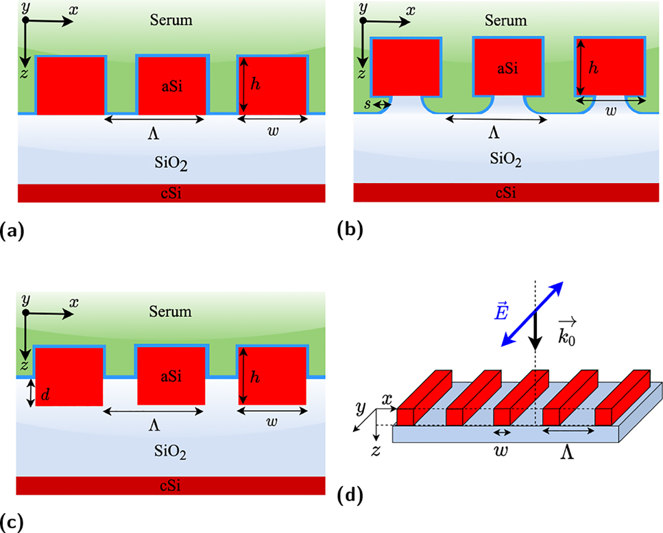
One-dimensional high contrast grating structures under consideration. Schematic design of (a) conventional, (b) pedestal, and (c) half-buried HCG structures. Note that thin blue layers around HCG structures are assumed to be the analyte layers in serum (n = 1.35) background, in green. (d) Illustration of the structure under consideration in a three-dimensional drawing where the considered incident polarization is depicted. Simulations were performed by considering normal incidence and with an electric field aligned parallel to the grating bars.
2 Numerical analysis
Figure 1 illustrates the considered HCG designs, which we optimized to manifest the largest possible resonance shift in response to a thickness variation of a thin coating analyte layer (thin blue line) while immersed in human serum. The structures were simulated by considering a practical implementation, where SOI wafers would be manufactured by first depositing an SiO2 layer, and then amorphous silicon (aSi) on top of a blank crystalline silicon (cSi) wafer. We applied various numerical methods to conduct thorough numerical simulations of the optimized designs: the commercial finite difference time-domain (FDTD) method (Ansys Lumerical Inc., version 2020 R2.2) and finite element method (COMSOL Inc., COMSOL Multiphysics), as well as two homemade methods: rigorous coupled-wave analysis (RCWA) [36, 37] and method of lines (MoL) [38] implemented on MATLAB. We found excellent agreement between results provided by all methods witnessing validity of the drawn conclusions.
The starting point was to reproduce results from literature [5, 16] with the structures optimized to manifest the narrowest possible resonance close to 1550 nm when immersed in human serum. Refractive index of serum was assumed to be n = 1.35. As the top layer can be deposited by low-pressure chemical vapor deposition (LPCVD), material parameters were taken from the ellipsometry measurements after amorphous silicon deposition. Crystalline silicon and silicon dioxide were instead modelled by means of the Sellmeier equations with coefficients taken from [39].
Both the functionalization layer and the target biomarkers were simulated as a protein layer of identical refractive index (n = 1.5). Specifically, the structure is initially coated with a 5 nm-thick protein layer that represents the surface functionalization layer (experimental baseline). Then, the thickness of the same layer is increased to 8 nm in order to resemble the immobilized biomarkers binding to antibodies [40]. As a result of such layer thickness increase the resonance wavelength is red-shifted. Basically, this model assumes a uniform biomarker coating of the whole grating structure, which can be related to the maximum detectable concentration of such proteins. A more accurate model could be developed, for instance, by assuming a certain concentration of randomly arranged and oriented ellipsoids, thus applying effective medium theory (EMT) [41], [42], [43].
2.1 Conventional HCG
As shown in Figure 2a, we optimized the traditional HCG configuration, first by setting the periodicity in order to tune the structure for the wavelength range of interest, and second by calculating the dispersion diagram to identify the anticrossing point corresponding to strong coupling of the grating modes, hence appearing of a high-Q resonance, as thoroughly discussed in [5]. Finally, we found the grating duty-cycle corresponding to the phase-matching condition between Bloch modes in the grating plane, which allows to further maximize the resonance Q-factor (Figure 2b). Furthermore, we applied the aforementioned analyte model in order to identify the duty-cycle providing the optimal resonance redshift upon increase of the protein layer thickness by 3 nm, as shown in Figure 2c.
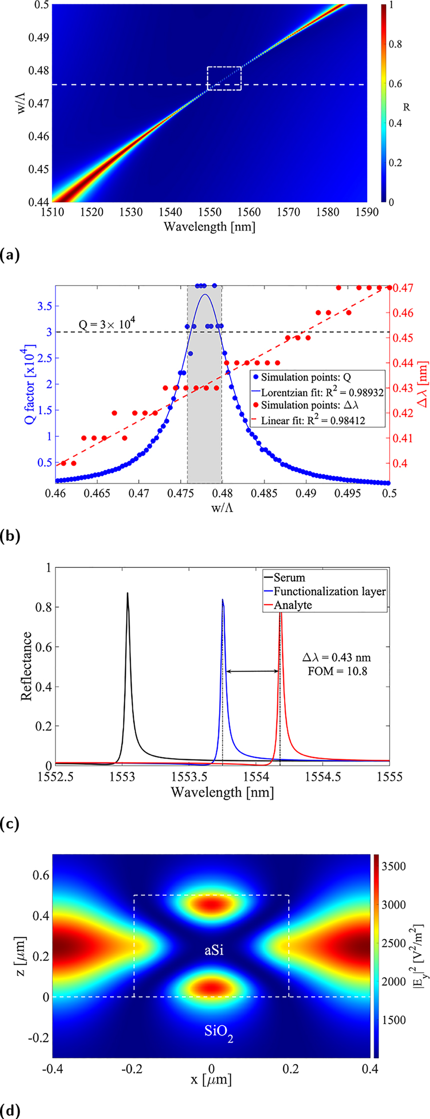
Optical response of conventional HCG structures. (a) Reflectance contour plot versus wavelength and duty-cycle, (b) Q-factor and resonance redshift as a function of duty cycle, (c) calculated reflection spectra for the an HCG without coating layer (black), with functionalization layer (blue), and with immobilized biomarker (red), and (d) field-intensity enhancement (|E y |2) at resonance in a unit cell calculated by the FDTD. Note that in (a) the box with white dashed line indicate the region where FOM is between its maximum and half, indicating the parameter space where FOM is high.
It is customary [23, 44] in the sensing community to define an FOM which relates the sensitivity, S (wavelength shift of resonance), and full-width half-maximum (FWHM) of the resonance, namely by
thus quantifying the goodness of the sensor under investigation. Moreover, we calculated the bulk refractive index sensitivity, S BRIS, of each structure defined as
where Δλ is the shift of the resonance wavelengths as opposed to the change of background liquid’s refractive index Δn, and RIU stands for the refractive index unit. S BRIS is also a general indication of sensors sensitivity toward the change of a bulk refractive index of the background liquid. In our study, the interest lies in the sensitivity towards the change of the refractive index at the nanoscale proximity to the grating surface.
We found that the experienced redshift manifests a linear trend as a function of the grating bars width, most likely due to the extended grating surface that can accommodate an increased amount of proteins sitting on the high-index structures. The staircase-like pattern of the red simulation points is due to a truncation of the redshift to 10 pm. Figure 2d shows the typical field profile of the HCG structures. Note, that the excitation field in Figure 2d was set to E 0 = 1 V/m, hence the color bar represents the field-intensity enhancement. The field profile suggests that the fields on top of the silicon grating surface mainly contribute to the sensing of analyte, and we confirmed this statement with our simulations.
2.2 Pedestal HCG
The physics of HCGs heavily relies on a large refractive index contrast between grating bars and their surroundings resulting in high-Q resonances. The index contrast of standard structures can be increased even further by partial etching of the substrate beneath the grating, thus suspending the grating bars on glass pedestals (Figure 1b). Such configuration allows for narrowing down the resonances and increasing their Q-factor. Furthermore, in this way the sensing area increases as well, as a larger portion of the grating surface will be exposed to the environment. All these aspects contribute to maximizing the sensing FOM (Eq. (1)), hence bringing an important advantage in terms of practical experimental implementation.
We repeated the same series of analysis for pedestal HCG structures by running large parametric sweeps. The optimal grating geometry resulted to be unvaried with respect to the standard implementation, as shown in Figure 3a, meaning that the maximum Q-factor is achieved in correspondence of the same duty-cycle previously found. In the case of pedestal structures, the Q-factor enhancement depends on the achieved etch depth as the structure progressively tends to the ideal implementation of completely suspended grating bars as can be seen from Figure 3b. Note that a lorentzian fit accompanies the simulation points in order to compensate for numerical inaccuracy related to resolution of such extremely narrow spectral features. Similarly, the resonance redshift is enhanced with deeper etch due to extended sensing area upon increase of the protein layer thickness and, importantly, the field hot-spot at the bottom grating interface is eventually becoming accessible in virtue of the HCG suspension. We would like to emphasize that the field profile of the pedestal HCG is very similar to that of a conventional HCG case except that the maximum intensity is enhanced due to the increased Q-factor. The spectral response of an s = 100 nm pedestal HCG is reported in Figure 3c.
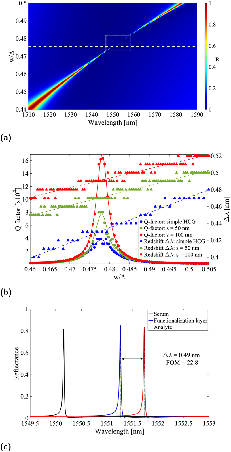
Optical response of pedestal HCG structures. (a) Reflectance contour plot versus wavelength and duty-cycle, (b) resonance Q-factor for conventional (blue), 50 nm (green) and 100 nm (red) pedestal HCG as a function of the grating duty-cycle, and (c) calculated reflection spectra for a 100 nm pedestal HCG without coating layer (black), with functionalization layer (blue) and with immobilized biomarker (red). Note that in (a) the white dashed line box indicates the region, where FOM is between the maximum and its half, indicating the parameter space of a high FOM. Note also that for the sake of keeping (b) readable, the entries describing the fitted curves have been omitted.
2.3 Half-buried HCG
The field profile outside the grating bars (i.e. in the air gaps) is more intense at the middle of the grating bars height, as shown in Figure 2d. Indeed, when simulating the conventional HCG with and without proteins on the SiO2 substrate, the sensitivity is not changing significantly. This is due to the low field-proteins overlap in the conventional HCG case. We employed the same model representing a uniform coating protein layer. In order to identify which part of the structure mostly contributes to sensing, we ran the simulations by first coating only the grating bars, then only the substrate. This showed that the main contribution comes from the actual grating (silicon) surface. Therefore, half-burying the grating bars in the glass substrate increases the interaction between the field and analyte layers, resulting in improved sensitivity, as illustrated in Figure 4. In this case, the duty-cycle providing the maximum Q-factor slightly decreases due to the phase difference introduced by the increased effective index in the air gaps, and the resonance is reasonably broadened with respect to the conventional implementation, yet retaining most of the HCG features, as shown in Figure 4a. An important parameter to be optimized is the percentage of silicon thickness buried in the glass substrate, which plays a relevant role in the tradeoff between amelioration of the Q-factor and device sensitivity as depicted in Figure 4b. The shaded area in Figure 4b represents the range of buried silicon thickness to be targeted during the fabrication. Incidentally, due to the broader resonance (Figure 4c) with a slower Q-factor trend as a function of the duty-cycle, the fabrication tolerance for this configuration is more relaxed. Furthermore, although the sensing FOM suffers an evident decrease as the result of resonance broadening, the redshift improvement largely compensates for such loss by reaching remarkable values, thanks to the enhanced overlap of fields and analyte (Figure 4d). Additionally, the region, in parametric space, of high-FOM values is greatly extended (Figure 4a), thus indicating that the design is more robust to parameter variations in terms of sensing performance then the previously described configurations. This is relevant as nanometer precision is not always achievable in nanofabrication, especially when the associated costs needs to be kept at a reasonable level.
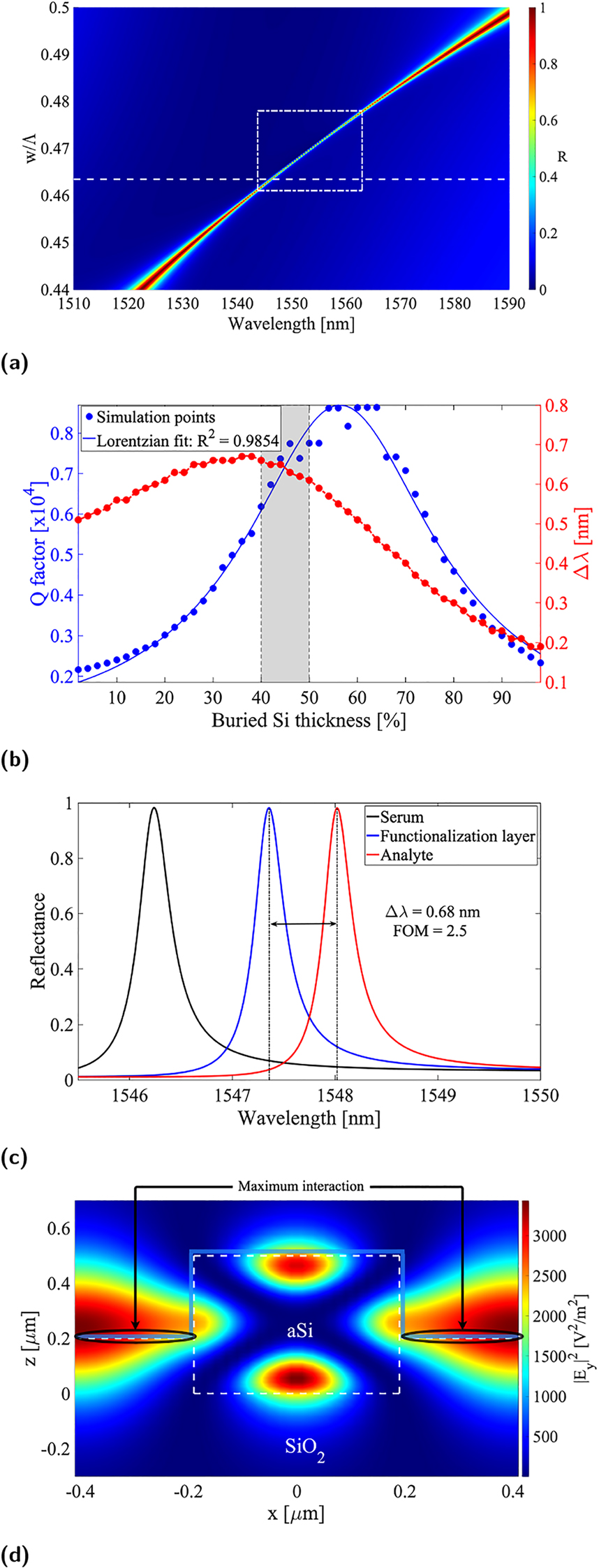
Optical response of half-buried HCG structures. (a) Reflectance contour plot versus wavelength and duty-cycle, (b) resonance Q-factor and redshift versus percentage of buried silicon thickness, (c) calculated reflection spectra for a 40% buried HCG without coating layer (black), with functionalization layer (blue) and with immobilized biomarker (red), and (d) field profile at resonance for a 40% buried HCG with highlight on the protein layer being optimally interfaced with it. Note that in (a) the white dashed line box indicates the region, where FOM is between the maximum and its half, indicating the parameter space of a high FOM.
3 Discussion and conclusions
Two novel HCG configurations, relying on different mechanisms to improve the performances of such platform in the context of biosensing, clearly provide practical advantages as they allow increasing the sensitivity of the device. On one hand, pedestal gratings mainly rely on increased index contrast and extended sensing area to maximize the FOM, while on other, half-buried HCGs are based on maximum field-proteins overlap by enhancing the interaction with analytes being captured at the substrate level. Table 1 lists geometrical parameters and resonance wavelength of the considered structures. Table 2 resumes the findings and compares different configurations. Overall, 100 nm pedestal HCGs provide a ∼12% increase in the redshift and a 210% improvement in the FOM, while 40% buried HCGs manifest a ∼58% redshift enhancement at the expense of FOM being roughly 23% that of conventional realizations.
Geometrical parameters of considered HCG configurations.
| HCG design | w [nm] | h [nm] | Λ [nm] | λ 0 [nm] |
|---|---|---|---|---|
| Conventional | 390 | 500 | 820 | 1553.1 |
| Pedestal | 390 | 500 | 820 | 1550.2 |
| Half-buried | 380 | 500 | 820 | 1546.2 |
-
The table refers to s = 100 nm pedestal and d = 40% buried HCGs. The corresponding resonance wavelength (λ 0) is also reported for the case of an uncoated grating (black curves in Figures 2c, 3c, 4c) for completeness. The geometrical parameters do not perfectly correspond to the maximum achievable Q-factor as we rounded them to the nearest multiple of 10 nm accounting for fabrication tolerances.
Comparison of optical responses between three studied HCG configurations.
| HCG design | Δλ | FWHM | Q | FOM | S BRIS |
|---|---|---|---|---|---|
| [nm] | [nm] | [×104] | [nm/RIU] | ||
| Conventional | 0.43 | 0.04 | 3.9 | 10.8 | 278 |
| Pedestal | 0.49 | 0.01 | 15.5 | 22.8 | 291 |
| Half-buried | 0.68 | 0.27 | 0.7 | 2.5 | 193 |
-
The table refers again to s = 100 nm pedestal and d = 40% buried HCGs. Note that resolving such an extremely narrow resonance is complicated when running large parametric sweeps, and as such the FWHM of pedestal gratings is limited by the algorithm spectral resolution, which was set to 0.01 nm in this case. The wavelength redshift, Δλ, is induced by a 3 nm-increase in protein layer thickness. S BRIS is calculated by Eq. (2) for the background (serum) refractive index change of Δn = 1.30–1.40.
The bulk refractive index sensitivity S BRIS of the pedestal design is improved from conventional one, which has similar values as for reported Si gratings [20], due to an extended grating surface interfacing with the environment. The buried configuration instead suffers from reduction of S BRIS due to the opposite reason: a smaller portion of grating is exposed to the surroundings.
There have been numerous realizations of sensor structures by GMR on dielectric grating on top of dielectric slab waveguide, known as guided-mode resonant gratings (GMRGs) or RGMFs [18]. One of the main limitations of such GMR-based sensors is their moderate quality factor, Q, on the order of a few hundreds while the bulk refractive index sensitivity, S BRIS, is similar to our design of a few hundreds nm/RIU. Our proposed design can achieve higher Q-factor and narrow FWHM by the geometrical parameters and hence high FOM.
As indicated by the white dashed line boxes in Figures 2a, 3a, and a4a, the high FOM regions of the conventional and pedestal designs are smaller in parameter space, w/Λ, and more sensitive to the change of geometrical parameters due to their narrow resonances. On the other hand, FOM of the half-buried design is more tolerant to the change of geometrical parameter, w/Λ. Additionally, another advantage provided by such Si-based structures is the reduced production cost associated with such materials and the well-developed processes suitable for mass-scale production.
To conclude we have proposed two novel designs of dielectric high-contrast gratings in the context of biosensing for the detection of thin protein layers. Comprehensive numerical study reveals the significant improvement in the FOM and/or resonance wavelength shift. Pedestal HCGs show remarkably large resonance Q-factors, which can be progressively increased by extending the etch depth during their fabrication. We foresee that such platform may efficiently serve in other applications, where narrow spectral responses and extreme field-enhancement are of interest, for instance, in signal filtering and nonlinear optics. Buried HCGs instead appear to be the most promising design for applications in biosensing as they allow probing proteins by the most intense field localization, previously inaccessible in the conventional HCGs structures, while still retaining a narrow resonance in the wavelength range of interest.
Funding source: The Independent Research Fund Denmark (DFF Research)
Award Identifier / Grant number: 8022-00387B
Funding source: The Danish National Research Foundation - "NanoPhoton" - Center for NanophotonicsTarbiat Modares University
Award Identifier / Grant number: DNRF147
Award Identifier / Grant number: Unassigned
Acknowledgment
The authors would like to acknowledge the support from the Danish National Center for Micro- and Nanofabrication (DTU Nanolab). G. F. acknowledges Prof. Domenico de Ceglia (Univeristy of Padova, Italy) who provided the RCWA code. M. Z. B. acknowledges Prof. Keyvan Forooraghi and Prof. Zahra Atlasbaf from Tarbiat Modares University of Tehran, Iran for supporting her stay at DTU.
-
Author contributions: G. F. conducted numerical analysis by FDTD and RCWA. M. Z. B. performed numerical analysis by MoL. L. V. simulated by FEM. O. T., P. E. A., and A. V. L. conceived the idea of the research. All authors were involved in the discussion and manuscript writing.
-
Research funding: Authors acknowledge financial support from The Independent Research Fund Denmark (DFF Research Project 2, “PhotoHub” 8022-00387B) and the Danish National Research Foundation (“NanoPhoton” – Center for Nanophotonics, DNRF147).
-
Conflict of interest statement: The authors declare no conflict of interest.
References
[1] R. Magnusson and S. S. Wang, “New principle for optical filters,” Appl. Phys. Lett., vol. 61, pp. 1022–1024, 1992. https://doi.org/10.1063/1.107703.Search in Google Scholar
[2] S. S. Wang and R. Magnusson, “Theory and applications of guided-mode resonance filters,” Appl. Opt., vol. 32, p. 2606, 1993. https://doi.org/10.1364/ao.32.002606.Search in Google Scholar PubMed
[3] S. Tibuleac and R. Magnusson, “Reflection and transmission guided-mode resonance filters,” J. Opt. Soc. Am. A, vol. 14, p. 1617, 1997. https://doi.org/10.1364/josaa.14.001617.Search in Google Scholar
[4] R. Magnusson, M. Shokooh-Saremi, K. J. Lee, et al.., “Leaky-mode resonance photonics: an applications platform,” Nanoengineering: Fabrication, Properties, Optics, and Devices VIII, vol. 8102, p. 810202, 2011. https://doi.org/10.1117/12.896431.Search in Google Scholar
[5] C. J. Chang-Hasnain and W. Yang, “High-contrast gratings for integrated optoelectronics,” Adv. Opt. Photon., vol. 4, p. 379, 2012. https://doi.org/10.1364/aop.4.000379.Search in Google Scholar
[6] G. Quaranta, G. Basset, O. Martin, and B. Gallinet, “Recent advances in resonant waveguide gratings,” Laser Photon. Rev., vol. 12, pp. 1–31, 2018. https://doi.org/10.1117/1.jnp.12.016004.Search in Google Scholar
[7] P. S. Priambodo, T. A. Maldonado, and R. Magnusson, “Fabrication and characterization of high-quality waveguidemode resonant optical filters,” Appl. Phys. Lett., vol. 83, pp. 3248–3250, 2003. https://doi.org/10.1063/1.1618930.Search in Google Scholar
[8] Y. Kanamori, T. Kitani, and K. Hane, “Guided-mode resonant grating filter fabricated on silicon-on-insulator substrate,” Jpn. J. Appl. Phys., vol. 45, pp. 1883–1885, 2006. https://doi.org/10.1143/jjap.45.1883.Search in Google Scholar
[9] K. Lee, R. LaComb, B. Britton, et al.., “Silicon-layer guided-mode resonance polarizer with 40 nm bandwidth,” IEEE Photon. Technol. Lett., vol. 20, pp. 1857–1859, 2008. https://doi.org/10.1109/lpt.2008.2004777.Search in Google Scholar
[10] D. Wawro, P. Priambodo, and R. Magnusson, “Resonating periodic waveguides as ultraresolution sensors in biomedicine,” Nanoengineering: Fabrication, Properties, Optics, and Devices, vol. 5515, p. 52, 2004. https://doi.org/10.1117/12.560192.Search in Google Scholar
[11] J. Wang, L. Chen, S. Kwan, F. Liu, and X. Deng, “Resonant grating filters as refractive index sensors for chemical and biological detections,” J. Vac. Sci. Technol., B: Microelectron. Nanometer Struct., vol. 23, p. 3006, 2005. https://doi.org/10.1116/1.2101774.Search in Google Scholar
[12] R. Magnusson, Y. Ding, K. J. Lee, P. S. Priambodo, and D. Wawro, “Characteristics of resonant leaky-mode biosensors,” Nanosensing: Materials and Devices II, vol. 6008, p. 60080U, 2005. https://doi.org/10.1117/12.634094.Search in Google Scholar
[13] H. N. Daghestani and B. Day, “Theory and applications of surface plasmon resonance, resonant mirror, resonant waveguide grating, and dual polarization interferometry biosensors,” Sensors, vol. 10, pp. 9630–9646, 2010. https://doi.org/10.3390/s101109630.Search in Google Scholar PubMed PubMed Central
[14] D. Threm, Y. Nazirizadeh, and M. Gerken, “Photonic crystal biosensors towards on-chip integration,” J. Biophot., vol. 5, pp. 601–616, 2012. https://doi.org/10.1002/jbio.201200039.Search in Google Scholar PubMed
[15] H. Shafiee, E. Lidstone, M. Jahangir, et al.., “Nanostructured optical photonic crystal biosensor for HIV viral load measurement,” Sci. Rep., vol. 4, pp. 1–7, 2014. https://doi.org/10.1038/srep04116.Search in Google Scholar PubMed PubMed Central
[16] T. Sun, S. Kan, G. Marriott, and C. Chang-Hasnain, “High-contrast grating resonators for label-free detection of disease biomarkers,” Sci. Rep., vol. 6, pp. 1–7, 2016. https://doi.org/10.1038/srep27482.Search in Google Scholar PubMed PubMed Central
[17] J. Baker, R. Sriram, and B. Miller, “Two-dimensional photonic crystals for sensitive microscale chemical and biochemical sensing,” Lab Chip, vol. 15, pp. 971–990, 2015. https://doi.org/10.1039/c4lc01208a.Search in Google Scholar PubMed PubMed Central
[18] G. Pitruzzello and T. Krauss, “Photonic crystal resonances for sensing and imaging,” J. Opt., vol. 20, pp. 1–23, 2018. https://doi.org/10.1088/2040-8986/aac75b.Search in Google Scholar
[19] J. Langer, D. J. de Aberasturi, J. Aizpurua, et al.., “Present and future of surface-enhanced Raman scattering,” ACS Nano, vol. 14, pp. 28–117, 2020.10.1021/acsnano.9b04224Search in Google Scholar PubMed PubMed Central
[20] D. Maksimov, V. Gerasimov, S. Romano, and S. Polyutov, “Refractive index sensing with optical bound states in the continuum,” Opt. Express, vol. 28, p. 38907, 2020. https://doi.org/10.1364/oe.411749.Search in Google Scholar PubMed
[21] D. Rosenblatt, A. Sharon, and A. A. Friesem, “Resonant grating waveguide structures,” IEEE J. Quant. Electron., vol. 33, pp. 2038–2059, 1997. https://doi.org/10.1109/3.641320.Search in Google Scholar
[22] M. Limonov, M. Rybin, A. Poddubny, and Y. Kivshar, “Fano resonances in photonics,” Nat. Photonics, vol. 11, pp. 543–554, 2017. https://doi.org/10.1038/nphoton.2017.142.Search in Google Scholar
[23] M. Svedendahl, S. Chen, A. Dmitriev, and M. Käll, “Refractometric sensing using propagating versus localized surface plasmons: a direct comparison,” Nano Lett., vol. 9, pp. 4428–4433, 2009. https://doi.org/10.1021/nl902721z.Search in Google Scholar PubMed
[24] S. Aćimović, M. Ortega, V. Sanz, et al.., “LSPR chip for parallel, rapid, and sensitive detection of cancer markers in serum,” Nano Lett., vol. 14, pp. 6–11, 2014.10.1021/nl500574nSearch in Google Scholar PubMed
[25] B. Špačková, P. Wrobel, M. Bocková, and J. Homola, “Optical biosensors based on plasmonic nanostructures: a review,” Proc. IEEE, vol. 104, pp. 2380–2408, 2016. https://doi.org/10.1109/jproc.2016.2624340.Search in Google Scholar
[26] O. Yavas, S. Aćimović, J. Garcia-Guirado, et al.., “Self- calibrating on-chip localized surface plasmon resonance sensing for quantitative and multiplexed detection of cancer markers in human serum,” ACS Sens., vol. 3, pp. 1376–1384, 2018. https://doi.org/10.1021/acssensors.8b00305.Search in Google Scholar PubMed
[27] B. Cunningham, M. Zhang, Y. Zhuo, L. Kwon, and C. Race, “Recent advances in biosensing with photonic crystal surfaces: a review,” IEEE Sensor. J., vol. 16, pp. 3349–3366, 2016. https://doi.org/10.1109/jsen.2015.2429738.Search in Google Scholar
[28] H. Inan, M. Poyraz, F. Inci, et al.., “Photonic crystals: emerging biosensors and their promise for point-of-care applications,” Chem. Soc. Rev., vol. 46, pp. 366–388, 2017. https://doi.org/10.1039/c6cs00206d.Search in Google Scholar PubMed PubMed Central
[29] S. Isaacs, A. Hajoj, M. Abutoama, A. Kozlovsky, E. Golan, and I. Abdulhalim, “Resonant grating without a planar waveguide layer as a refractive index sensor,” Sensors, vol. 19, pp. 1–13, 2019. https://doi.org/10.3390/s19133003.Search in Google Scholar PubMed PubMed Central
[30] S. Romano, G. Zito, S. Torino, et al.., “Label-free sensing of ultralow-weight molecules with all-dielectric metasurfaces supporting bound states in the continuum,” Photon. Res., vol. 6, pp. 726–733, 2018. https://doi.org/10.1364/prj.6.000726.Search in Google Scholar
[31] F. Yesilkoy, E. R. Arvelo, Y. Jahani, et al.., “Ultrasensitive hyperspectral imaging and biodetection enabled by dielectric metasurfaces,” Nat. Photonics, vol. 13, pp. 390–396, 2019. https://doi.org/10.1038/s41566-019-0394-6.Search in Google Scholar
[32] S. Romano, M. Mangini, E. Penzo, et al.., “Surface refractive index imaging based on quasi-bound states in the continuum,” ACS Nano, vol. 14, pp. 15417–15427, 2020. https://doi.org/10.1021/acsnano.0c06050.Search in Google Scholar
[33] N. Bhalla, S. Sathish, C. Galvin, R. Campbell, A. Sinha, and A. Shen, “Plasma-assisted large-scale nanoassembly of metal-insulator bioplasmonic mushrooms,” ACS Appl. Mater. Interfaces, vol. 10, pp. 219–226, 2018. https://doi.org/10.1021/acsami.7b15396.Search in Google Scholar
[34] M. Garín, M. Solà, A. Julian, and P. Ortega, “Enabling silicon-on-silicon photonics with pedestalled Mie resonators,” Nanoscale, vol. 10, pp. 14406–14413, 2018. https://doi.org/10.1039/c8nr02259c.Search in Google Scholar
[35] P. Lin, V. Singh, J. Hu, et al.., “Chip-scale mid-infrared chemical sensors using air-clad pedestal silicon waveguides,” Lab Chip, vol. 13, pp. 2161–2166, 2013. https://doi.org/10.1039/c3lc50177a.Search in Google Scholar
[36] M. Moharam and T. Gaylord, “Rigorous coupled-wave analysis of planar-grating diffraction,” J. Opt. Soc. Am. B, vol. 71, pp. 811–818, 1981. https://doi.org/10.1364/josa.71.000811.Search in Google Scholar
[37] A. Khavasi, A. Kazemi Jahromi, and K. Mehrany, “Longitudinal Legendre polynomial expansion of electromagnetic fields for analysis of arbitrary-shaped gratings,” J. Opt. Soc. Am. A, vol. 25, p. 1564, 2008. https://doi.org/10.1364/josaa.25.001564.Search in Google Scholar
[38] M. Bideskan, K. Forooraghi, and Z. Atlasbaf, “Method of lines for analysis of plane wave scattering by periodic arrays of magnetically-biased graphene strips,” Sci. Rep., vol. 11, pp. 1–13, 2021. https://doi.org/10.1038/s41598-021-86882-z.Search in Google Scholar
[39] E. Palik, Handbook of Optical Constants of Solids, vol. 1. USA, Academic Press, 2012.Search in Google Scholar
[40] E. Shkondin, T. Repän, E. M. P. Aryaee, A. Lavrinenko, and O. Takayama, “High aspect ratio plasmonic nanotrench structures with large active surface area for label-free mid-infrared molecular absorption sensing,” ACS Appl. Nano Mater., vol. 1, pp. 1212–1218, 2018. https://doi.org/10.1021/acsanm.7b00381.Search in Google Scholar
[41] S. M. Rytov, “Electromagnetic properties of finely stratified medium,” Sov. Phys. - JETP, vol. 2, pp. 466–475, 1956.Search in Google Scholar
[42] V. M. Agranovich, “Dielectric permeability and influence of external fields on optical properties of surperlattices,” Solid State Commun., vol. 78, pp. 747–750, 1991. https://doi.org/10.1016/0038-1098(91)90856-q.Search in Google Scholar
[43] Y. W. X. Zhang, “Effective medium theory for anisotropic metamaterials,” Sci. Rep., vol. 5, pp. 1–7, 2015. https://doi.org/10.1038/srep07892.Search in Google Scholar PubMed PubMed Central
[44] T. Chung, S. Lee, E. Song, H. Chun, and B. Lee, “Plasmonic nanostructures for nano-scale bio-sensing,” Sensors, vol. 11, pp. 10907–10929, 2011. https://doi.org/10.3390/s111110907.Search in Google Scholar PubMed PubMed Central
© 2021 Giovanni Finco et al., published by De Gruyter, Berlin/Boston
This work is licensed under the Creative Commons Attribution 4.0 International License.
Articles in the same Issue
- Frontmatter
- Editorial
- The science of harnessing light’s darkness
- Reviews
- Bound states in the continuum in resonant nanostructures: an overview of engineered materials for tailored applications
- Reconfigurable nonlinear response of dielectric and semiconductor metasurfaces
- Research Articles
- Active angular tuning and switching of Brewster quasi bound states in the continuum in magneto-optic metasurfaces
- Resonance-forbidden second-harmonic generation in nonlinear photonic crystals
- Dispersive bands of bound states in the continuum
- Dressed emitters as impurities
- Engineering gallium phosphide nanostructures for efficient nonlinear photonics and enhanced spectroscopies
- Ultraviolet second harmonic generation from Mie-resonant lithium niobate nanospheres
- Label-free DNA biosensing by topological light confinement
- Guided-mode resonance on pedestal and half-buried high-contrast gratings for biosensing applications
- Ways to achieve efficient non-local vortex beam generation
- Fabrication robustness in BIC metasurfaces
- Bound states in the continuum in periodic structures with structural disorder
- Demonstration of on-chip gigahertz acousto-optic modulation at near-visible wavelengths
- Integrated diffraction gratings on the Bloch surface wave platform supporting bound states in the continuum
- Ultrahigh-Q system of a few coaxial disks
- Bound states in the continuum in strong-coupling and weak-coupling regimes under the cylinder – ring transition
- Two tractable models of dynamic light scattering and their application to Fano resonances
- Polarization-independent anapole response of a trimer-based dielectric metasurface
- Transparent hybrid anapole metasurfaces with negligible electromagnetic coupling for phase engineering
- Nonradiating sources for efficient wireless power transfer
- Anapole-enabled RFID security against far-field attacks