Frequency domain analysis of a piezoelectric energy harvester with impedance matching network
-
Michele Bonnin

 und
Kailing Song
und
Kailing Song

Abstract
Piezoelectric energy harvesters are electromechanical systems, capable to convert ambient dispersed mechanical vibrations into usable electrical energy. They can be used for supplying power to sensors and actuators that are wireless connected, miniaturized and remote located. In this work, we analyze piezoelectric energy harvesters for mechanical vibrations in the frequency domain. White Gaussian and colored noise models for random vibrations are considered. The governing equations for the harvester are derived from mechanical properties, the characteristic relationships of piezoelectric materials, and circuit description of the electrical load. We show that the energy harvester can be modelled by cascade connected electromechanical two-ports, and that frequency domain methods are the perfect tool for analysis. Formulas for the harvested power and power efficiency are derived. We also show that application of matching networks reduces the impedance mismatch between the mechanical and the electrical parts, significantly increasing the harvested power and power efficiency. The matching network solution is compared to others, previously proposed solutions, such as application of power-factor correction. We show that the matching network offers nine times more average power and better power efficiency than the unmatched resistive load, and increases by more than 10% the harvested power and efficiency, with respect to the power-factor corrected solution.
Introduction
Wireless sensor and actuator networks (WSANs) are the hardware backbone of the Internet of Things (IoT). WSANs may involve hundreds of nodes that share some common features: they are wireless connected, miniaturized, and in some cases, remote located and difficult to access. Old fashioned solutions for powering WSANs, e.g. batteries, are far from being ideal, because despite the recent advancements, batteries remain relatively bulky and heavy. Systems capable of self-powering, collecting energy dispersed in the surrounding environment that would otherwise be wasted, would represent the perfect solution. Technical solutions to scavenge ambient energy go by the name of energy harvesting (Paradiso and Starner 2005; Priya and Inman 2009; Roundy, Wright, and Rabaey 2003).
Ambient is a potentially unlimited energy source. Energy is dispersed in the environment in various form, with solar and wind power being the most abundant and, consequently, also the most exploited. Solar and wind power are mature technologies, but they require outdoor application and large structures. Therefore, they are not suitable to supply power to wireless, miniaturized, remote located electrical circuits and systems. Conversely, sources such as thermal gradients, dispersed electromagnetic waves and parasitic mechanical vibrations are negligible at the macro-scale, but are suitable to supply power to WSANs (Beeby, Tudor, and White 2006; Khaligh, Zeng, and Zheng 2009; Lu et al. 2015; Mann and Sims 2009; Mitcheson et al. 2008).
Ambient mechanical vibrations are particularly attractive, because of their widespread diffusion, their relatively high power density and, most importantly, because they can be easily converted into usable electrical power. Various physical mechanisms can be exploited for power conversion, including magnetic induction, electrostatic conversion, and piezoelectricity. Piezoelectric transducers are perhaps the preferred solution, thanks to their low cost, easy of manufacturing, and because they can be miniaturized.
Because the power conveyed by parasitic vibrations is limited (ranging from μW to few mW), it is of paramount importance designing energy harvesters as efficient as possible. A major problem is represented by the frequency mismatch between parasitic vibrations, mechanical structure, whose working frequency ranges from few Hz to some hundred Hz, and the electrical part, whose typical working frequency is much higher. To cope with the problem, ingenious solutions have been recently devised, to realize mechanical structures that are capable to adjust their resonant frequency, matching the spectral interval where most of vibrations are concentrated (Shin et al. 2020; Wang et al. 2021). Other researchers focused more on the electrical domain of the harvesters. In (Bonnin et al. 2021; Huang, Shengxi, and Grzegorz 2019; Yu and Zhou 2021), it was shown that the harvested power and power efficiency can be significantly improved, reducing the lag between the voltage across and the current through the electrical load, a procedure known in circuit theory as power-factor correction. Power factor correction is obtained placing an inductive element in parallel with the resistive load, to compensate the capacitive reactance of piezoelectric transducers.
In a previous work (Bonnin et al. 2022), we have shown that power performances of energy harvester can be boosted, at least for the case of purely sinusoidal vibrations, through impedance matching. Impedance matching is another classical solution of circuit theory, specifically in RF problem, to eliminate the impedance mismatch between a source (in this case the mechanical part of the harvester), and a load (the electrical part), maximizing the power transfer from the former to the latter. In this work, we extend the results of (Bonnin et al. 2022) to energy harvesters subject to random vibrations, either Gaussian white or colored noise, and we develop an analysis technique, based on transmission parameters representation and frequency domain analysis, specifically suited to study matching networks composed by multistage circuits.
The paper is organized as follows. In Section 2 we describe the modelling of piezoelectric energy harvesters for ambient mechanical vibrations. The governing equations are derived from mechanical properties, the characteristic equations of piezoelectric materials, and the circuit description of electrical loads. In Section 3 we describe the basics of frequency domain analysis for evaluating the power performances of electromechanical systems. We show that energy harvesters can be described by cascade connected two-ports. As a first main contribution, we derive formulas for the harvested power and power efficiency, for both Gaussian white and colored noise, modelled as an Ornstein-Uhlenbeck process. In Section 4 we show the application of frequency domain analysis to an energy harveste, with different type of loads. As a second main contribution, we show that application of impedance matching networks significantly increases the average harvested power and power efficiency. Finally, Section 5 is devoted to conclusions.
System modeling
A scheme of a cantilever beam piezoelectric energy harvester for ambient mechanical vibrations is shown in Figure 1. One end of a beam is fixed to a vibrating support, with an inertial mass m at the opposite end. Mechanical vibrations of the support produce oscillations of the beam, that are amplified by the inertial mass. Oscillations induce mechanical stress and strain in the beam, that are converted into electrical current by a layer of piezoelectric material that covers the beam. Eventually, a properly designed matching network can be interposed between the piezoelectric transducer and the load, with the goal to reduce the impedance mismatch between the two parts, increasing the electric power absorbed by the load.
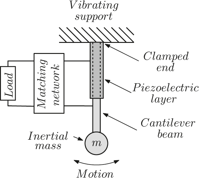
Schematic representation of a piezoelectric energy harvester for ambient mechanical vibrations.
Mechanical vibrations modeling
Ambient mechanical vibrations are random in nature, and thus they are best described as a stochastic process. If vibrational energy is distributed over a sufficiently broad spectral interval, ambient vibrations can be modeled by white Gaussian noise (Bonnin, Traversa, and Bonani 2020). White Gaussian noise is the “formal” derivative of a Wiener process Wt = W(t), characterized by zero mean 〈Wt〉 = 0 (symbol 〈⋅〉 denotes mean value), covariance
As a matter of fact, the energy of ambient mechanical vibrations is often concentrated at low frequencies. Thus, a low-pass filtered white Gaussian noise can be a more realistic model for parasitic vibrations. Consider the low-pass filter circuit shown in Figure 2, where the input voltage source is a white Gaussian noise process:
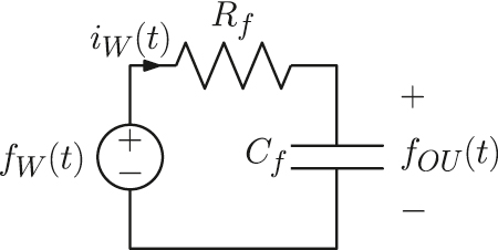
Low-pass filter circuit to generate an Ornstein-Uhlenbeck process.
Voltage fOU(t) is called Ornstein-Uhlenbeck process (OUP). It is characterized by the expectation
where fOU(0) is a deterministic initial condition, and by the time correlation function
For the current iW we have
where Gf = 1/Rf is the conductance of the resistor.
Mechanical-to-electrical analogies implies that forces can be replaced by voltages (and vice-versa), and velocities by currents. Thus we shall model the force of random mechanical vibrations by fOU(t), and the velocity of the vibrating support by iW(t). The results are readily adapted to the case where mechanical vibrations are modelled as a white Gaussian noise process fW(t), as in corollaries 2 and 3.
Energy harvester modelling
To derive the governing equations for the mechanical part, we shall make some simplifying hypothesis. First, we shall assume that the masses of the cantilever beam and of the piezoelectric layer are negligible with respect to the inertial mass. Second, we shall assume that the oscillation amplitude is so small with respect to the cantilever length, that the arc described by the inertial mass can be approximated by a straight line. The small oscillation amplitude also justify neglecting nonlinear contributions in the beam stiffness.
Under this simplifying assumptions, the Lagrange equation of motion for the mechanical part is
where m is the inertial mass, x is the mass displacement with respect to the rest position, k is the elastic constant of the beam, γ is the damping coefficient, and fOU(t) (possibly fW(t)), fpz(t) are the forces exerted by mechanical vibrations and the piezoelectric layer, respectively. If mechanical vibrations are best described by a white Gaussian noise, the OUP fOU(t) will be replaced by
For the piezoelectric transducer, we start from the constitutive relationships for linear piezoelectric materials (Priya and Inman 2009). Neglecting the stiffness of the piezoelectric layer, the following relationships between mechanical and electrical variables are obtained, through spatial integration of the local variables in the tensor equations:
where α is the electro-mechanical coupling factor (in N/V or As/m), Cpz is the electrical capacitance of the piezoelectric layer, q(t) is the electrical charge, and e(t) is the output voltage. Equation (7) imply that piezoelectric conversion is completely reversible, because the same coupling constant α is used for both mechanical-to-electrical and electrical-to-mechanical conversion. A detailed discussion about modelling of piezoelectric material can be found in (Jones and Nenadic 2013). The piezoelectric transducer is assumed to be lossless, with all dissipations accounted for by the damping coefficient γ. Such a model has been extensively used in literature (Bonnin et al. 2021; Daqaq et al. 2014; Huang, Shengxi, and Grzegorz 2019; Yang, Erturk, and Zu 2017; Yu and Zhou 2021; Zhou et al. 2016).
Finally, we consider the electrical part. We shall consider three different loads: a simple resistive load, a power-factor corrected load, and impedance matched load. The latter two architectures were recently proposed as solutions to increase the harvested power and the power efficiency (Bonnin et al. 2021; Bonnin et al. 2022; Huang, Shengxi, and Grzegorz 2019; Yu and Zhou 2021). It is worth mentioning that, in general, other interface circuits can be interposed between the transducer and the load, such as rectifier circuits designed to increase the harvested power (Dicken et al. 2012). In this work we restrict the attention to relatively simple, easy to implement structures. The representation we shall give, based on cascade connected two-ports networks, can be easily extended to include more stages, and our frequency domain analysis method, also applies to more complicated structures.
Resistive load
In circuit theory, a load is any element that absorb power from the rest of the circuit. Loads are typically represented by resistors. In the simplest setup, the resistor is connected directly to the output of the piezoelectric transducer (see Figure 3a). Application of Ohm law gives

The three different load setup considered: (a) Resistive load. (b) Power factor corrected (resistive-inductive) load. (c) Matched load.
Power factor corrected (resistive-inductive) load
Several works have shown that the harvested average power and power efficiency can be significantly increased through power factor correction (Bonnin et al. 2021; Huang, Shengxi, and Grzegorz 2019; Yu and Zhou 2021). Power factor correction is a standard method of electrical engineering. It permits to reduce the lag between the voltage across, and the current through a load, thus increasing the average power absorbed by the latter. Given the capacitive reactance of piezoelectric transducers, power factor correction is obtained inserting an inductive element in parallel with the resistive load, as in Figure 3b. Applying Kirchhoff voltage and current laws (KVL and KCL), and using the constitutive relationship of linear inductors
Combining together (6), (7) and (9) yields the state equations for the energy harvester with power-factor corrected load:
Matched load
In (Bonnin et al. 2022), it was shown that the main limiting factor to the performances of piezoelectric energy harvester, is the impedance mismatch between the mechanical and the electrical part. Impedance mismatch is a classical problem in electrical engineering. A possible solution consists in interposing an impedance matching network between the source (the piezoelectric transducer) and the load, as shown in Figure 3c. The matching network not only reduces the impedance mismatch, but it can also be designed to resonate at a chosen frequency, not necessarily coincident with the resonant frequency of the energy harvester. This characteristic is very useful when the resonant frequency of the energy harvester and the frequency where vibrational energy is concentrated are far apart (Bonnin et al. 2022). Here we show that application of a matching network offers significant advantages, both in terms of average harvested power and power efficiency, also in the case of random vibrations. We consider the simple low-pass L-matching network shown in Figure 3c. It is composed by two reactive elements, an inductor LS and a capacitor CP, connected to form an L-structure. Application of KVL and KCL yields
Combining together (6), (7), and (11) gives the state equations for the energy harvester with matched load:
Frequency domain analysis
For a linear time invariant system (LTI) the input-output relation takes the form
where h(t) is the step response, x(t), y(t) are the input and the output, respectively, and
Taking the Fourier transform we obtain the well known relation between input and output power spectral densities
where
By the Wiener–Khinchin theorem (Gardiner 1985), the power spectral density (PSD) is the Fourier transform of the correlation function. The PSD for white Gaussian noise fW(t) is
which reflects the well known fact that energy content for white noise is constant over all frequencies. For the OUP fOU(t) we have
We shall now apply frequency domain analysis to the energy harvester models described in Section 2. Energy harvesters are electromechanical two-ports, that can be conveniently described in terms of transmission parameters. Consider the frequency domain representation of a generic electromechanical two-port in Figure 4a, where s = jω is complex frequency,

(a) Frequency domain representation of a generic electromechanical two port network. At the left port are the mechanical quantities, force and velocity. At the right port the electrical quantities, voltage and current. The two port is conveniently described by the transmission or ABCD matrix T(s). (b) Representation of the energy harvested by cascade connected electromechanical two-ports. The relevant quantities at each port are given in the frequency domain.
The transmission or ABCD matrix T(s) defines the relationships between mechanical quantities at the input and electrical quantities at the output
The transmission matrix T(s) can be easily derived taking advantage of the structure of the energy harvester, that is composed by cascade connected two-port networks, as it is shown in Figure 4b. Starting from the filter representation of the OUP, by Laplace transforming Equations (1) and (4) we have
where TOU(s) is the transmission matrix for the OUP.
Denoting by TM(s) the transmission matrix for the mechanical part, and taking the Laplace transform of Equations (7) we have
Similarly, denoting with Tpz(s) the transmission matrix of the piezoelectric transducer, and taking the Laplace transform of (8) yields
where
Finally, we consider the two types of two-port networks designed to improve the output average power and power efficiency of the harvester. Taking the Laplace transform of the constitutive relationships for power factor correction network (9), the following expression for the transmission matrix TPF(s) is obtained:
For the low-pass L-matching network, by Laplace transforming the time domain relationships (11), the transmission matrix Tmat(s) is obtained:
The total transmission matrix for cascade connected two-ports, is the matrix product of the transmission matrices. Therefore the transmission matrix of the energy harvester subject to OUP noise is:
It is worth mentioning that:
More than one matching network can be included, forming a ladder of cascade connected matching networks. In this case one can use
The case of mechanical vibrations described by white Gaussian noise is straightforward. The only difference is that the matrix TOU(s) does not appear in Equation (24) and matrix T(s) is replaced by
The transmission matrix T′(s) will also be instrumental to calculate the power efficiency. We shall now use the transmission matrix to derive a set of useful formulas.
Theorem 1.
(Power Balance equation)
Irrespective of the type of load, the power balance equation for the energy harvester takes the form
Proof.
We illustrate the proof for the case of the matched load. The cases of the resistive load and the power-factor corrected load are analogous. The total energy stored in the harvester is the sum of the kinetic energy of the mass, the elastic potential energy of the beam, the capacitive energy stored in the piezoelectric transducer and the reactive energies stored in the reactive elements of matching network
Taking the derivative with respect to time and using equations (12) yields
and taking expectations the thesis follows.□
The power balance equation implies that the harvester will eventually reach a steady state, where the power transferred from the OUP noise to the harvester Pin = 〈fOU(t)y〉, will equal the power dissipated by friction Pγ = γ〈y2〉 plus power absorbed by the load
Theorem 2.
(Harvested power formula)
For an energy harvester subject to OUP noise, described by one of the transmission matrices T (s) of equation (24), the average power absorbed by the load GLis
Proof.
Consider the two-port network shown in Figure 4(a), closed on the resistor with conductance GL, then
Corollary 1.
(Alternative formula for the harvested power)
An equivalent formula to calculate the harvested power is
with
Proof.
From equations (20)–(23) we have
that implies (32) for
Corollary 2.
(Harvested power formula for white Gaussian noise)
In the case vibrations are described by white Gaussian noise, the harvested power is still given by (29), with
Proof.
It follows directly from theorem 2 and the definition of the transmission matrix for the white Gaussian noise scenario.□
Theorem 3.
(Power efficiency formula)
For an energy harvester subject to OUP noise, described by one of the transmission matrices T (s) of equation (24), the power efficiency is
Proof.
The power efficiency is defined as the ratio between the power absorbed by the load, and the power injected by the noise. From theorem 1, we have that at steady state
Corollary 3.
For white G. noise vibrations, the power efficiency is given by (34), with
Proof.
The proof is analogous to that of theorem 3, with SOU(ω) replaced by SW(ω) = ε2.□
Results
To verify whether the low-pass L-matching network solution offers advantages in terms of average harvested power and power efficiency with respect to previously proposed solutions, we have applied frequency domain analysis to energy harvesters with resistive, power-factor corrected, and low-pass L-matched loads. The parameters used in the analysis are adapted from previous works, where models based on equivalent circuits were used (Bonnin et al. 2021; Bonnin et al. 2022; Yang and Tang 2009). The values where determined setting the tip inertial mass equal to 1, and deriving all other quantities consequently. It is worth mentioning that the inertial mass not only determines the resonant frequency of the mechanical domain, but also the maximum power harvested at that frequency and the bandwidth. Choice of the tip mass is always a trade-off between maximum harvested power and bandwidth. A change in the mass aimed at increasing the former, inevitably decreases the latter, and vice-versa. The role of the tip mass have been throughly investigated, and ingenious solution to design tunable systems have been devised (Shin et al. 2020; Wang et al. 2021). Parameters values are summarized in Table 1.
Values of parameters used in the analysis. The first six values are adapted from (Yang and Tang 2009).
| Parameter | Value |
|---|---|
| γ | 6.9366 N s/m |
| k | 1.7024 105 N/m |
| m (normalized) | 1 |
| C pz | 80.08 nF |
| R L | 1 M Ω |
| α | 0.0267198 N/V (as/m) |
| ε | 10 −2 N |
| τ | 10 −3 s |
Figure 5 shows the average harvested power and the power efficiency for the energy harvester with power-factor corrected load, versus the value of the inductance L. The average harvested power and the power efficiency shows the same behavior and are maximum for
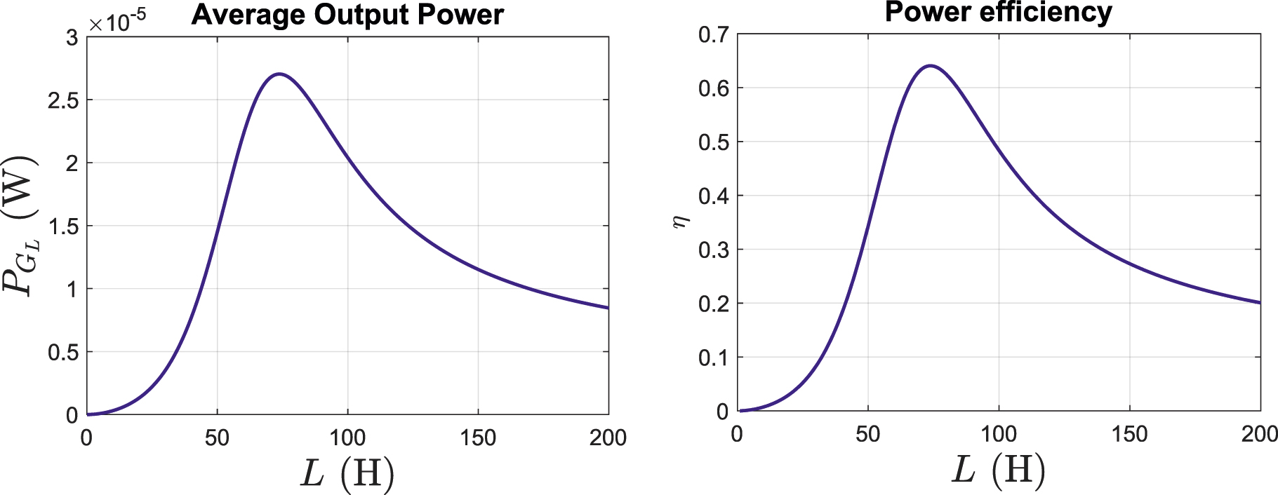
Output average power (on the left) and power efficiency (on the right) versus the inductance value L, for an energy harvester with power-factor corrected load.
Average harvested power and power efficiency for the energy harvester with different load setups.
| Configuration |
|
η |
|---|---|---|
| Resistive load | 3.4857 μW | 8.27% |
| Power-factor corrected load | 27.033 μW | 64.05% |
| Low-pass L matched load | 31.614 μW | 74.97% |
| Two stages low-pass L matched load | 35.992 μW | 85.32% |
Figure 6 shows the average harvested power and power efficiency for the energy harvester with low-pass L-matching network, versus the values of the matching parameters LS and CP. The average harvested power and the power efficiency are maximum for the same values of the components
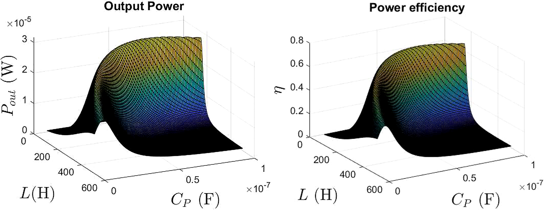
Output average power (on the left) and power efficiency (on the right) versus the inductance value LS and the capacity CP, for an energy harvester with low-pass L-matching network.
Finally, Figure 7 shows the amplitude response

Comparison between the amplitude responses of a linear harvester with resistive load (R load), power-factor corrected (
Conclusions
Piezoelectric energy harvesters are micro-electro-mechanical systems, capable to convert ambient dispersed mechanical vibrations into usable electrical energy. They can be used for supplying power to electronic circuits, sensors and actuators, that are wireless connected, miniaturized and remote located.
In this work we have analyzed piezoelectric energy harvesters for ambient mechanical vibrations. The governing equations are derived from the mechanical properties, the characteristic equations of linear piezoelectric materials and the circuit description of the electrical domain. We show that energy harvesters can be modelled by cascade connected two port electromechanical networks. Consequently, the governing equations are formulated in terms of transmission matrices and transmission parameters, and are efficiently analyzed in the frequency domain. As a first main contribution, formulas for the harvested power and power efficiency for energy harvesters subject to both white Gaussian colored noise mechanical vibrations are given.
The most important limiting factor for vibrational energy harvesting, is the impedance mismatch between the mechanical and the electrical parts. As a second main contribution, we show that interposing a matching network between the piezoelectric transducer and the electrical load, the impedance mismatch is significantly reduced. The power performances of the harvester are increased by a large amount: In particular, the maximum average harvested power and the power efficiency are nine times better with respect to a simple, unmatched resistive load. Application of a matching network offers better performances also with respect to other, recently proposed solutions, such as the application of power-factor correction methods.
-
Author contributions: All the authors have accepted responsibility for the entire content of this submitted manuscript and approved submission.
-
Research funding: None declared.
-
Conflict of interest statement: The authors declare no conflicts of interest regarding this article.
References
Beeby, S. P., M. J. Tudor, and N. White. 2006. “Energy Harvesting Vibration Sources for Microsystems Applications.” Measurement Science and Technology 17: R175, https://doi.org/10.1088/0957-0233/17/12/r01.Suche in Google Scholar
Bonnin, M., F. L. Traversa, and F. Bonani. 2021. “Leveraging Circuit Theory and Nonlinear Dynamics for the Efficiency Improvement of Energy Harvesting.” Nonlinear Dynamics 104: 367–82.10.1007/s11071-021-06297-3Suche in Google Scholar
Bonnin, M., F. L. Traversa, and F. Bonani. 2022. “An Impedance Matching Solution to Increase the Harvested Power and Efficiency of Nonlinear Piezoelectric Energy Harvesters.” Energies 15: 2764.10.3390/en15082764Suche in Google Scholar
Bonnin, M., F. L. Traversa, and F. Bonani. 2020. “Analysis of Influence of Nonlinearities and Noise Correlation Time in a Single-DOF Energy-Harvesting System via Power Balance Description.” Nonlinear Dynamics 100: 119–33, https://doi.org/10.1007/s11071-020-05563-0.Suche in Google Scholar
Daqaq, M. F., R. Masana, A. Erturk, and D. Dane Quinn. 2014. “On the Role of Nonlinearities in Vibratory Energy Harvesting: a Critical Review and Discussion.” Applied Mechanics Reviews 66 (4): 040801–1, https://doi.org/10.1115/1.4027259.Suche in Google Scholar
Dicken, J., P. D. Mitcheson, I. Stoianov, and E. M. Yeatman. 2012. “Power-extraction Circuits for Piezoelectric Energy Harvesters in Miniature and Low-Power Applications.” IEEE Transactions on Power Electronics 27 (11): 4514–29, https://doi.org/10.1109/tpel.2012.2192291.Suche in Google Scholar
Gardiner, C. W. 1985. Handbook of Stochastic Methods. Berlin: Springer.Suche in Google Scholar
Shin, Y. H., J. Choi, S. J. Kim, S. Kim, D. Maurya, T. H. Sung, S. Priya, C. Y. Kang, and H. C. Song. 2020. “Automatic Resonance Tuning Mechanism for Ultra-wide Bandwidth Mechanical Energy Harvesting.” Nano Energy 77: 104986, https://doi.org/10.1016/j.nanoen.2020.104986.Suche in Google Scholar
Huang, D., Z. Shengxi, and L. Grzegorz. 2019. “Analytical Analysis of the Vibrational Tristable Energy Harvester with a Resonant Circuit.” Nonlinear Dynamics 97: 663–77, https://doi.org/10.1007/s11071-019-05005-6.Suche in Google Scholar
Jones, T. B., and N. G. Nenadic. 2013. Electromechanics and MEMS. Cambridge: Cambridge University Press.10.1017/CBO9781139032605Suche in Google Scholar
Khaligh, A., P. Zeng, and C. Zheng. 2009. “Kinetic Energy Harvesting Using Piezoelectric and Electromagnetic Technologies—State of the Art.” IEEE Transactions on Industrial Electronics 57: 850–60.10.1109/TIE.2009.2024652Suche in Google Scholar
Lu, X., P. Wang, D. Niyato, D. I. Kim, and Z. Han. 2015. “Wireless Networks with RF Energy Harvesting: A Contemporary Survey.” IEEE Communication Survey Tutorials 17: 757–89, https://doi.org/10.1109/comst.2014.2368999.Suche in Google Scholar
Lossouarn, B., M. Aucejo, J.-F. Deü, and B. Multon. 2017. “Design of Inductors with High Inductance Values for Resonant Piezoelectric Damping.” Sensors and Actuators, A Physical 259: 68–76, https://doi.org/10.1016/j.sna.2017.03.030.Suche in Google Scholar
Mitcheson, P., E. Yeatman, G. Rao, A. Holmes, and T. Green. 2008. “Energy Harvesting from Human and Machine Motion for Wireless Electronic Devices.” Proceedings of the IEEE 96: 1457–86, https://doi.org/10.1109/jproc.2008.927494.Suche in Google Scholar
Mann, B. P., and N. D. Sims. 2009. “Energy Harvesting from the Nonlinear Oscillations of Magnetic Levitation.” Journal of Sound and Vibration 319: 515–30, https://doi.org/10.1016/j.jsv.2008.06.011.Suche in Google Scholar
Øksendal, B. 2003. Stochastic Differential Equations. Berlin: Springer.10.1007/978-3-642-14394-6Suche in Google Scholar
Paradiso, J. A., T. Starner,“Energy Scavenging for Mobile and Wireless Electronics” IEEE Pervasive Comput., 4 (2005): 18–27.https://doi.org/10.1109/mprv.2005.9.Suche in Google Scholar
Priya, S., and D. J. Inman. 2009. Energy Harvesting Technologies. Boston: Springer.10.1007/978-0-387-76464-1Suche in Google Scholar
Roundy, S., P. K. Wright, and J. M. Rabaey. 2003. Energy Scavenging for Wireless Sensor Networks. Boston: Springer.10.1007/978-1-4615-0485-6Suche in Google Scholar
Wang, Z., Y. Du, T. Li, Z. Yan, and T. Tan. 2021. “A Flute-Inspired Broadband Piezoelectric Vibration Energy Harvesting Device with Mechanical Intelligent Design.” Applied Energy 303: 117577, https://doi.org/10.1016/j.apenergy.2021.117577.Suche in Google Scholar
Yu, T., and S. Zhou. 2021. “Performance Investigations of Nonlinear Piezoelectric Energy Harvesters with a Resonant Circuit under White Gaussian Noises.” Nonlinear Dynamics 103: 183–96, https://doi.org/10.1007/s11071-020-06170-9.Suche in Google Scholar
Yang, Z., A. Erturk, and J. Zu. 2017. “On the Efficiency of Piezoelectric Energy Harvesters.” Extreme Mechanics Letter 15: 26–37, https://doi.org/10.1016/j.eml.2017.05.002.Suche in Google Scholar
Yang, Y., and L. Tang. 2009. “Equivalent Circuit Modeling of Piezoelectric Energy Harvesters.” Journal of Intelligent Material Systems and Structures 20 (18): 2223–35, https://doi.org/10.1177/1045389x09351757.Suche in Google Scholar
Zhou, S., J. Cao, D. J. Inman, J. Lin, and D. Li. 2016. “Harmonic Balance Analysis of Nonlinear Tristable Energy Harvesters for Performance Enhancement.” Journal of Sound and Vibration 373: 223–35, https://doi.org/10.1016/j.jsv.2016.03.017.Suche in Google Scholar
© 2022 Walter de Gruyter GmbH, Berlin/Boston
Artikel in diesem Heft
- Frontmatter
- Review
- A comprehensive review on electric vehicles: charging and control techniques, electric vehicle-grid integration
- Research Articles
- Evaluation of parameters influencing the performance of photovoltaic-thermoelectric (PV-TE) hybrid system
- Dispatchable power supply from beam down solar point concentrator coupled to thermal energy storage and a Stirling engine
- Modelling, design and parametric analysis of a levitation based energy harvester
- Performance optimization of flywheel using experimental design approach
- Assessment and optimization of photovoltaic systems at the University Ibn Tofail according to the new law on renewable energy in Morocco using HOMER Pro
- Optimizing hybrid power system at highest sustainability
- Preparation of Na2HPO4⋅12H2O-based composite PCM and its application in air insulated box
- The efficiency of linear electromagnetic vibration-based energy harvester at resistive, capacitive and inductive loads
- A numerical investigation of optimum angles for solar energy receivers in the eastern part of Algeria
- Experimental investigation of soiling effects on the photovoltaic modules energy generation
- Frequency domain analysis of a piezoelectric energy harvester with impedance matching network