Study on interference and protection of pipeline due to high-voltage direct current electrode
-

 ,
,

Abstract
To study the rules of interference and protective measures on buried pipelines of high-voltage direct current (HVDC), the influence of different factors, including current into soil, soil resistance, damaged rate of coatings, and electrode-to-pipe distance, on pipe-to-soil potential deviation were simulated. Based on the simulated results, the fitted equations and interference judgment pattern were also obtained. The protective measures of insulation and cathodic protection can be performed for buried pipelines to prevent the interference, but the cathodic protection in the isolated area may become the stray current source of the other pipe section. This study can provide suggestions for the evaluation of interference and protective measures of pipelines of HVDC.
1 Introduction
The high-voltage direct current (HVDC) transmission system is commonly a bipolar symmetric connection mode. During normal running, the leakage current into soil is just less than 1% of the running current (Cui et al., 2015). However, once the system malfunctions, it turns into a single mode, which means that the current into soil can reach thousands of amperes that have significant influence on buried metal facilities (Crabtree et al., 1985; Ying, 2014; Gong et al., 2015; Zhang et al., 2015).
Focusing on the severity of the interference of HVDC, Nicholson (2010) found that HVDC fault current flows into buried pipelines, lasting for several days along the pipelines until outflowing with serious corrosion. Some field tests were also performed to study the influence on pipeline and facilities of HVDC. According to our research, when 3000 A current flows into soil from a certain grounding electrode, potential deviation can reach 50 V at the location of the insulating flange, making great damage for related facilities.
Numerical methods have been shown to be a powerful tool to analyze corrosion problems in the last two decades. Numerical methods used for corrosion studies include the finite difference method (FDM), the finite element method (FEM; Xu & Cheng, 2013), and the boundary element method (BEM; Metwally et al., 2007; Boumaiza & Aour, 2014). BEM was applied to model cathodic protection systems in the early 1980s (Lan et al., 2012; Liu et al., 2013). Compared to FDM and FEM, BEM requires the meshing of the boundary only. As a result, BEM needs fewer equations resulting in a smaller matrix size than FEM and can solve both finite and infinite domain problems (Jia et al., 2004; Parvanova et al., 2014). Last but not least, BEM has been specifically developed to calculate the DC induced in pipeline networks by transmission system and can model the soil and the entire system (Bortels et al., 2007).
In this paper, BEM was carried out to determine the interference and protective measures on buried pipelines under the influence of HVDC. It focuses on the influence of the fault current of electrode, damaged rate of coatings, soil resistance, pipe-to-electrode distance, and protective measures.
2 Mathematical model of the problem
2.1 Governing equation
Assume that the soil is uniform and electroneutral. Therefore, according to Ohm’s law, the current density i can be described by the following equation:
where i is the current density (A/m2), E is the electric field (V/m), and ρsoil is the soil resistance (Ω m).
Assume that there is no electric charge in this system and the current of electrode is static, so the electrostatic field formed by the current is stable, the character of which can be described by potential φ. Then, the static form of the equation can be given as
Therefore, the governing equation of electric distribution under the above assumptions can be described by the Laplace equation:
2.2 Boundary conditions
When HVDC is in unipolar mode, the current into soil is stable and known, rated current and equipotential boundary was set by far enough earth. Therefore, the boundary can be described by following equations:
In this paper, the ground boundary is treated as an insulating surface, which means that the normal current density through this surface is 0. Therefore,
where n is the normal direction of the ground boundary.
where Rp is the pipe resistance and Rc is the pipe-to-earth resistance.
On the surface of the cathode, many complex electrochemical reactions occur. Polarization is one such consequence of these reactions. The polarization data will be used as the cathodic boundary. The steel’s polarization curves with different damaged areas were measured in soil using a conventional three-electrode cell assembly. Rectangular platinum shapes were used as the counter electrode and a saturated copper sulfate electrode works as the reference. The working electrode was a cuboid, and its material was X65 steel. The steel electrode was embedded in epoxy resin so that only 1 cm2 area of the cuboid was exposed to the soil. Before the experiment, the working electrode was polished gradually using a 600–1200 grid waterproof abrasive paper. It was then washed with distilled water, degreased with acetone, and washed with ethanol. Finally, it was dried in an unheated air stream. Electrochemical measurements were carried out using electrochemical workstation Parstat 2273, which was specially designed for the study of the electrochemical corrosion behavior. In this paper, the Tafel curve was tested, and the polarization measurement involved a scan starting from 0 to −250 mV vs. OCP at a scan rate of 0.3 mV/s.
The polarization curve is used as the cathode boundary condition, but it is a nonlinear curve, so we have to use polarization data in a piecewise linear interpolation approach (Abootalebi et al., 2010; Liu et al., 2013).
2.3 Basal conditions of numerical simulation
According to the Xiluodu HVDC project, the basal conditions of numerical simulation were given in Table 1. The minimal pipe-to-electrode distance is 860 m, and the self-potential of pipe is −600 mV vs. saturated silver chloride reference electrode.
Basal conditions of numerical simulation.
| Parameter | Value |
|---|---|
| Normal operating voltage | ±800 kV |
| Normal operating current | 5000 A |
| Unbalanced current | 50 A |
| Depth of grounding electrode | 3.5 m |
| Soil resistance | 150 Ω m |
| Pipe diameter and wall thickness | φ 813×10 mm |
| Anticorrosive coating | 3PE |
| Depth of pipe | 2 m |
| Longitudinal resistance | 1×10⁻⁶ Ω m |
| Damaged rate of coatings | 1% |
2.4 Model verification
In Figure 1, a test pipe was buried in soil, the length of which is 3 m, the damaged rate of coatings is 1%, the depth is 0.5 m, and the soil resistance is 116 Ω m. Two breaking points of 1 cm2 were set as the location that current inflows or outflows. The pipe-to-soil potential was collected by the data acquisition unit. Figure 2 shows the cathodic polarization curve and piecewise linearization.
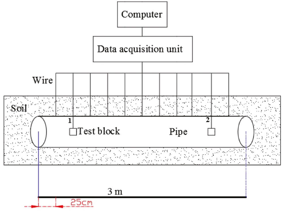
Test pipe for model validation.
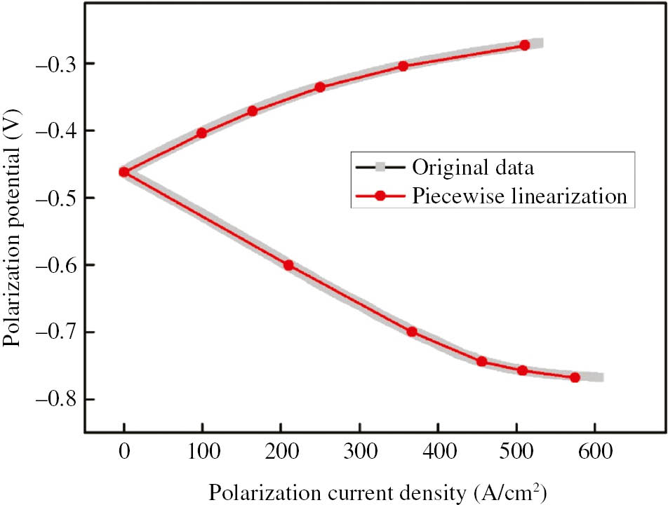
Experimental and piecewise polarization curves.
In this case, stray current flows into pipe from point 1 and out of pipe from point 2. The pipe-to-soil potential is almost constant in this short pipe so that final results are taken as the average potential of the whole pipe. Figure 3 shows the pipe-to-soil potential in different DC stray currents by experiment and simulated methods, respectively.
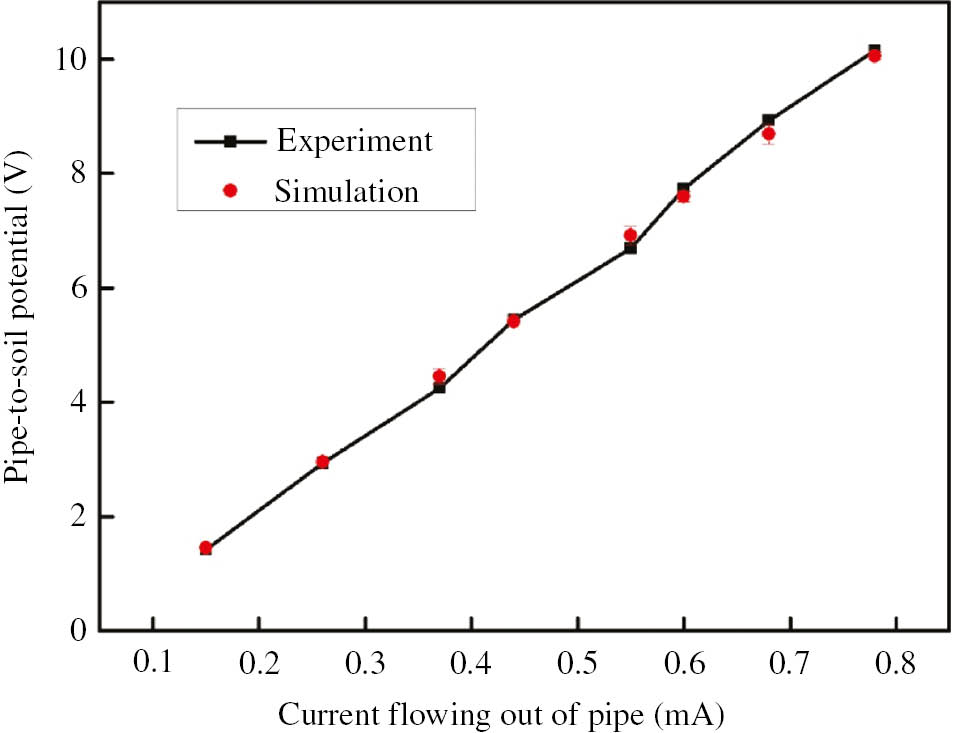
Experimental and simulated results under different DC interference.
It can be seen that the experimental data are in relatively good agreement with simulation results. Therefore, the mathematical model of the DC stray current interference is acceptable. This BEM modeling proves to be very effective for simulating HVDC interference on pipelines.
3 Results and analysis
3.1 Influencing factors
(1) Current into soil
Once the HVDC transmission system breaks down or maintains, the transmission mode turns into unipolar mode and then the earth works as a wire in the transmission system. Under these circumstances, the current returns to receiving electrode from sending electrode through soil. Thousand of amperes in soil can break down the cathodic protection facilities and hurt the operators. Therefore, the pipe-to-soil potential was simulated in different currents.
Figure 4 shows the relationship of potential deviation and current into soil. The maximal positive and negative deviation (named as PDM and NDM, respectively, which means maximal difference of pipe-to-soil potential with or without interference) are proportional to the current, and it is also similar within the range along the pipeline of 14 km. It is obvious that the smaller electrode-to-pipe distance is, the greater potential deviation is. Therefore, NDM appears at a point of minimal electrode-to-pipe distance, which is called Pdmin. However, when the range along pipeline is more than 14 km, the change does not meet with the above description.
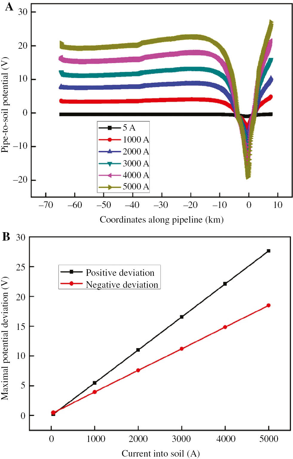
Curves of pipe-to-soil potential deviation in different current: (A) pipe-to-soil potential and (B) maximal pipe-to-soil potential deviation.
In this paper, the damage of coatings is assumed to be uniform, which means the inflowing and outflowing of current occur simultaneously at any point of pipe. Therefore, the potential deviation is the result of synthesis. In Figure 4, in the range of 0–14 km, current into pipe gradually decreases over distance. At 7 km, the balance of current inflowing and outflowing is reached, that is, the potential is almost equal to the natural potential. However, when the range is more than 14 km, the potential deviation is dominated by the current outflowing in this pipe section that is kept constant.
From the above analysis, when earth-fault current is set to 5000 A, PDM and NDM can reach 27.65 and 18.48 V, respectively, which can not only result in pipe pitting and anticorrosive coating delamination but also harm the operators. When HVDC runs normally, PDM and NDM are 0.2 and 0.45 V, respectively. According to the result of the field test, the pipe-to-soil potential can be kept flat by the cathodic protection system if the deviation is less than 1 V; meanwhile, the accumulation effect of stray current should be noted.
(2) Soil resistance
Soil resistance reflects soil electrical conductivity and all kinds of corrosive factors of underground metal facilities including water, organic, salt, texture, and other elements. It was found in the previous study that, in the model of vertical layers, if the surface soil resistance is far less than the following, the direct stray current is more likely to spread on the surface soil to make the range and severity more critical, and it also proves that the DC stray current trends to select the channel with lower resistance to spread. Compared to soil, the resistance of the pipe is smaller, which provides a better channel for current. Therefore, in this paper, the pipe-to-soil potential of pipe was simulated in different soil resistance using earth-fault current of 5000 A as an example.
Figure 5 shows the relationship of potential deviation and soil resistance. With the soil resistance increasing, NDM first increases sharply and then slightly, but PDM first increases and then decreases and is finally kept the same.
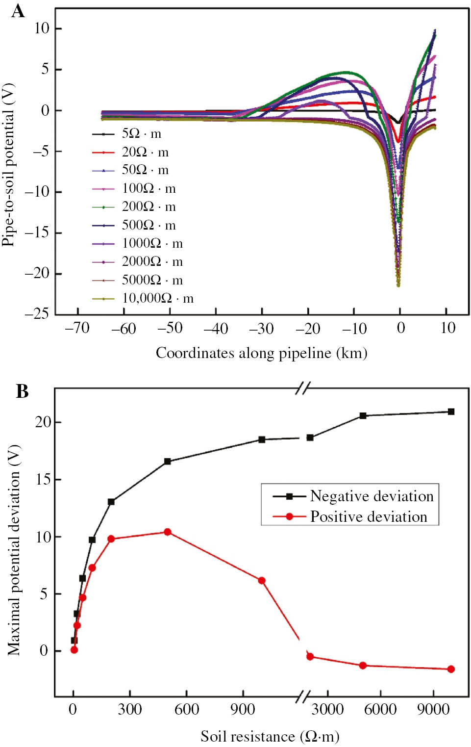
Curves of pipe-to-soil potential in different soil resistance: (A) pipe-to-soil potential and (B) maximal pipe-to-soil potential deviation.
According to the curve representing negative deviation, once the soil resistance is more than 600 Ω m, the variability of the potential slows down and then keeps flat. This is because the larger soil resistivity results in more uniform distribution and further transportation of current in the soil. Therefore, the current at the soil into pipe at Pdmin is kept the same basically. However, PDM appears at different points. From the curve on behalf of positive deviation, it shows a similar regulation. When the soil resistance is more than 600 Ω m, the degree of positive deviation gradually decreases; when the soil resistance is more than 2000 Ω m, the current flows along the pipe rather than flows from pipe to soil.
(3) Damaged rate of coatings
Coating is a commonly used method for buried pipe to prevent corrosion, which isolates pipe from corrosive media and prevents mechanical damage. However, damage of coatings not only makes reduced resistance and cathodic protection current loss but also increases the risk of local pitting. Therefore, in this paper, the pipe-to-soil potential of pipe was simulated in different coating damage rates using earth-fault current 5000 A as an example.
Figure 6 shows the relationship of potential deviation and damaged rate of coatings. With the increase of damaged rate, first PDM and NDM both increase sharply and then mostly kept plain. Especially, when the rate is more than 50%, the deviation is smaller, and the difference of PDM and NDM at rates 50% and 100% (bare pipe) is less than 400 mV. Therefore, under these circumstances, the amount of current flowing into pipe is constant, and PDM and NDM are more serious with a larger current density due to a smaller holiday.
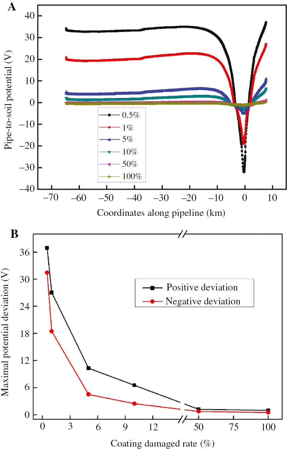
Curves of pipe-to-soil potential in different damaged rates of coatings: (A) pipe-to-soil potential and (B) maximal pipe-to-soil potential deviation.
In this paper, the potential deviation and current density with holidays of 1, 3, and 5 cm2 were simulated, whereas the other parts of coatings are in a uniformly damaged rate of 1%. Figure 7 and Table 2 show the contour fill and analyzed results in different areas of holidays, respectively. As the damaged areas increase from 1 to 5 cm2, the maximal potential appearing at the center of holidays decreases from −1.19 to −1.11 V, changing a little. However, with the increase of damaged areas, the minimal potential reduces to 0.33 V, whereas the current density decreases from 150.380 to 75.680 A/m2, which appears on the coatings close to the holidays. Therefore, the smaller the holiday is, the larger the current density is, which makes more serious influence; at the same time, the potential of coatings close to the holidays will be in a greater negative deviation that may result in hydrogen evolution reaction and then delamination.
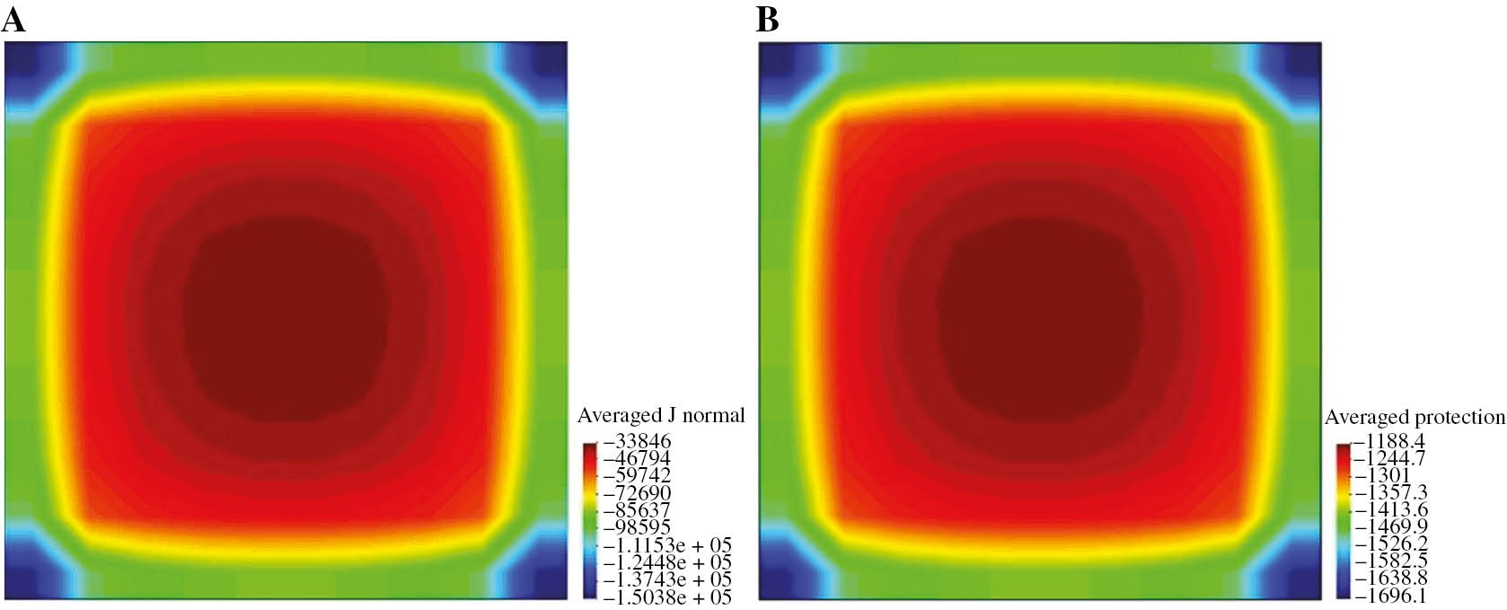
Contour fill of pipe-to-soil potential current density of 1 cm2 holiday: (A) pipe-to-soil potential and (B) distribution of current density.
Change of related parameters in different damaged area of holidays.
| Damaged area (cm2) | Maximal potential (V) | Minimal potential (V) | Current density (A/m2) |
|---|---|---|---|
| 1 | −1.19 | −1.70 | −150.380 |
| 3 | −1.13 | −1.46 | −95.452 |
| 5 | −1.11 | −1.37 | −75.670 |
(4) Pipe-to-electrode distance
According to the law of DL/T 5224-2014 “Technical rule for the design of HVDC earth return operation system”, the minimal pipe-to-electrode distance (d), the influence on these facilities of grounding electrode should be evaluated. Therefore, using earth-fault current 5000 A as an example, the pipe-to-soil potential of pipe was simulated in different distances, including 860 m, 10 km, 30 km, 60 km, and 100 km.
Figure 8 shows the relationship of potential deviation and pipe-to-electrode distance. In the distance of 0–30 km, the potential decreases sharply as the distance increases, and when the distance is more than 30 km, the trend becomes relatively flat. From the curve of distance 60 and 100 km, the potential keeps almost invariant compared to that of 0–60 km. It is because the increase of distance makes current distribution in soil more uniform, which expands the range and flows less into pipe. When the distance is more than 100 km, the pipe is not almost affected by the earth-fault current.
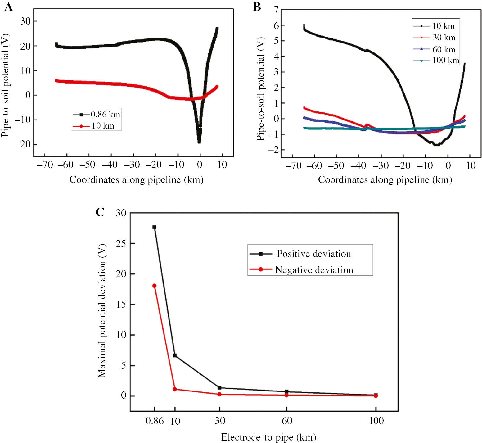
(A) and (B) are the curves of pipe-to-soil potential in different electrode-to-pipe distance. (C) Is the maximal pipe-to-soil potential deviation.
For another aspect, the field test found that when the pipe-to-electrode distance is about 67 km and the earth-fault current is 5000 A, the pipe-to-soil potential can be kept flat under the protection of the cathodic system. Therefore, in the projects, it is suggested that the pipe-to-electrode distance should not be less than 30 km, and at least, the influence on pipe should be evaluated within the scope of 60 km around the electrode.
3.2 Data fitting
In the study, the fitting formulas and regression coefficients of potential deviation were given by data fitting at Pdmin.
where P is the potential deviation at Pdmin.
It can be seen from the above R that good regression is presented between single factor x1 to x4 and P. For another, the four parameters are independent of each other. Therefore, multiple regression equation is established in the influence of four parameters:
3.3 Interference judgment
According to the above analysis, under the circumstances of current 5000 A and coating damaged rate 1%, Figure 9 shows the range of interference on buried pipelines of HVDC in different soil resistance and pipe-to-electrode distance. Based on the related regulations, interference of DC is wildly thought to exist if the potential deviation is more than 20 mV, and protective measures should be taken if the potential deviation is more than 100 mV. Therefore, Figure 9 is divided into three regions representing noninterfering, interference, and needed protection, respectively. Combined with the analysis and fitted equations, the interference can be approximately calculated to draw the conclusion whether it needs protective measures.
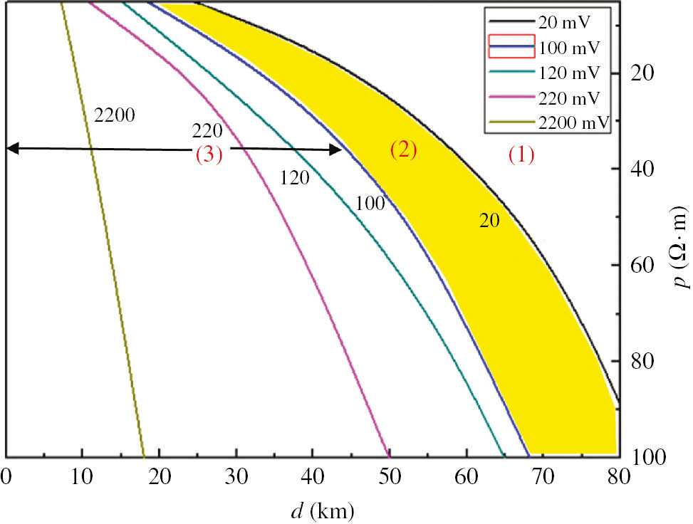
Range of interference of buried pipelines of HVDC.
4 Protective measures
Measures are needed to protect pipelines under DC interference such as drainage, cathodic protection, equipotential connection, insulation, and shield. However, for the interference of HVDC, on the one hand, because of unique characteristics such as the uncertainty of fault time, the effectiveness of traditional measures is doubtful; on the other hand, setting threshold current or voltage of drainage may cause cathodic protection fail. Therefore, based on the study of the effectiveness of traditional measures, the application of the combined methods was explored.
4.1 Insulation
It can be seen in Figure 8 that when the pipe-to-electrode distance is more than 30 km, the changes of maximal positive and negative deviation are slight, and when the distance exceeds 100 km, the interference is nearly negligible. Therefore, in this paper, the potential of pipe was simulated with insulation using earth-fault current 5000 A and distance 30 km as an example.
It can be seen in Figure 10 that the potential increases in insulated area, whereas another two parts are the opposite. However, it should be noted that the potential difference on both sides of insulating flange can reach 1.22 V, which may not only makes the operator get an electric shock and break down insulating flange but also accelerates internal corrosion around the insulating flange. Therefore, this method guarantees the another sections at the expense of the section closest to the electrode.
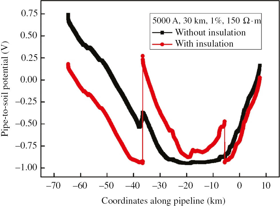
Influence on pipeline with insulation of HVDC.
4.2 Insulation and cathodic protection
Figure 11 shows the results of the combination of cathodic protection and isolation. The C curve in the figure is the result of the potential distribution with cathodic protection and insulation. On this occasion, the anodic output current is 5 A and the feeding point is set on the point where the potential is the largest. It can be seen that the potential of the whole isolated pipe decreases slightly and distributes unevenly, and another two parts are almost affected. The D curve is the result of the potential distribution with cathodic protection and insulation. On this occasion, the anodic output current of two sides is 50 A. The potential decreases sharply because of the increase of protection current, especially in the feeding point. However, on the other hand, the cathodic protection may become stray current for another two parts. Therefore, the pipe in the area of HVDC grounding electrode can be protected by combining insulation with cathodic protection, but it should be noted that the cathodic protection in isolated area may become the stray current source of the other pipe section.

Influence on the averaged protection potential of different protective measures: (A) without any protective measures, (B) insulation, (C) insulation + cathodic protection performed on the one side and anodic current 5 A, and (D) insulation + cathodic protection performed on both sides and anodic current 30 A.
5 Conclusions
The following conclusions can be drawn based on our experiments and simulation:
The mathematical model of the DC stray current interference in pipelines investigated in this paper is accurate, and BEM is confirmed to simulate DC stray current interference on pipelines very well.
Four factors, including current into soil, soil resistance, damaged rate of coatings, and pipe-to-electrode distance, have a greatly different influence on the pipe-to-soil potential. In this case, the pipe-to-soil potential of Pdmin is proportional to the current into soil, exponential to coating damage rate and distance, and logarithmic to soil resistance. Therefore, the current into soil has the greatest influence on potential deviation, but the pipe-to-electrode distance should be mainly considered when designing pipe route.
For protecting pipes in the interference area of HVDC, segmented isolation and cathodic protection can be carried out under the conditions of guaranteeing the maximal reasonable distance, but the interference on the pipe section out of the isolated area should be noted.
Acknowledgments
This work was supported by the Fundamental Research Funds for the Central Universities (18CX06034A) and also by the Shandong Provincial Key Laboratory of Oil & Gas Storage and Transportation Safety, Qingdao Key Laboratory of Circle Sea Oil & Gas Storage and Transportation Technology.
References
Abootalebi O, Kermanpur A, Shishesaz MR, Golozar MA. Optimizing the electrode position in sacrificial anode cathodic protection systems using boundary element method. Corros Sci 2010; 52: 678–687.10.1016/j.corsci.2009.10.025Search in Google Scholar
Bortels L, Dorochenko A, Vanden BB, Weyns G, Deconinck J. Three-dimensional boundary element method and finite element method simulations applied to stray current interference problems. A unique coupling mechanism that takes the best of both methods. Corrosion 2007; 63: 561–576.10.5006/1.3278407Search in Google Scholar
Boumaiza D, Aour B. On the efficiency of the iterative coupling FEM-BEM for solving the elasto-plastic problems. Eng Struct 2014; 72: 12–25.10.1016/j.engstruct.2014.03.036Search in Google Scholar
Crabtree IM, Mackey KJ, Kito K. Studies on electrolytic corrosion of hardware of DC line insulators. IEEE T Power App Syst 1985; 104: 645–654.10.1109/TPAS.1985.319000Search in Google Scholar
Cui G, Li ZL, Yang C, Wei X. Study on the interference corrosion of cathodic protection system. Corros Rev 2015; 33: 233–247.10.1515/corrrev-2014-0061Search in Google Scholar
Gong Y, Xue CL, Yuan ZL, Li YX, Dawalibi FP. Advanced analysis of HVDC electrodes interference on neighboring pipelines. J Power Energy Eng 2015; 3: 332–341.10.4236/jpee.2015.34045Search in Google Scholar
Jia JX, Song G, Atrens A, John DS, Baynham J, Chandler G. Evaluation of the BEASY program using linear and piecewise linear approaches for the boundary conditions. Mater Corros 2004; 55: 845–852.10.1002/maco.200403795Search in Google Scholar
Lan ZG, Wang XT, Hou BR, Wang ZF, Song JW, Chen SL. Simulation of sacrificial anode protection for steel platform using boundary element method. Eng Anal Bound Elem 2012; 36: 903–916.10.1016/j.enganabound.2011.07.018Search in Google Scholar
Liu GC, Sun W, Wang L, Li L. Modeling cathodic shielding of sacrificial anode cathodic protection systems in sea water. Mater Corros 2013; 63: 472–477.10.1002/maco.201206726Search in Google Scholar
Metwally IA, Al-Mandhari HM, Gastli A, Zhuang XG, Yuan ZK, Liu YH. Factors affecting cathodic protection interference. Eng Anal Bound Elem 2007; 31: 485–493.10.1016/j.enganabound.2006.11.003Search in Google Scholar
Nicholson P. High voltage direct current interference with underground or underwater pipelines. NACE Int 2010; 10102.10.5006/C2010-10102Search in Google Scholar
Parvanova SL, Dineva PS, Manolis GD, Kochev PN. Dynamic response of a solid with multiple inclusions under anti-plane strain conditions by the BEM. Comput Struct 2014; 139: 65–83.10.1016/j.compstruc.2014.04.002Search in Google Scholar
Xu LY, Cheng YF. Development of a finite element model for simulation and prediction of mechano-electrochemical effect of pipeline corrosion. Corros Sci 2013; 73: 150–160.10.1016/j.corsci.2013.04.004Search in Google Scholar
Ying B. The influence on safe operation of the long-distance pipeline of electrode of high voltage direct current transmission system [in Chinese]. Oil-Gasfield Surf Eng 2014; 33: 23–24.Search in Google Scholar
Zhang FZ, Luo B, Wang GL, Liao YF, Luo L. Study of test method for accelerated electrolytic corrosion of iron caps of DC disc porcelain insulators. IEEE T Dielect El In 2015; 22: 2937–2943.10.1109/TDEI.2015.005095Search in Google Scholar
©2019 Walter de Gruyter GmbH, Berlin/Boston
Articles in the same Issue
- Frontmatter
- In this issue
- Review
- Supramolecular concepts and approaches in corrosion and biofouling prevention
- Mini review
- Sulfate-reducing bacteria-assisted cracking
- Original articles
- Corrosion characteristics of an automotive coolant formulation dispersed with nanomaterials
- Pitting corrosion and effect of Euphorbia echinus extract on the corrosion behavior of AISI 321 stainless steel in chlorinated acid
- Study on interference and protection of pipeline due to high-voltage direct current electrode