New service limit state criteria for reinforced concrete in chloride environments
-
Arnaud Castel
 ,
Raoul François
,
Raoul François

Abstract
In chloride environments, reinforcement stress limits, intended to control flexural cracking, are one of the most important requirements for service limit state (SLS) design. However, concrete damage at the steel-concrete interface between bending cracks, so called cover-controlled cracking, is always correlated to areas of severe steel reinforcement corrosion. Based on the assumption that cover-controlled cracking should be limited, a model has been developed to provide alternative reinforcement stress limits in marine exposure conditions such as concrete in sea water, including permanently submerged, spray zone and tidal/splash zone, as well as coastal constructions located within 1 km of the shoreline. In this paper, the new reinforcement stress limitation is compared to the Australian Standards AS3600 concrete building code and AS5100.5 concrete bridge code provisions. Analysis shows that the new model is very sensitive to the reinforcement percentage of the cross-section. As a result, the existing AS3600 and AS5100.5 code provisions are more conservative than the new limitation for lightly to normally reinforced concrete cross-section. In this case, crack width control governs the SLS design. However, for normally to heavily reinforced concrete cross-section, the new model provides more conservative results suggesting that cover-controlled cracking governs the SLS design.
1 Introduction
The high degree of alkalinity of Portland cement-based concrete provides a natural protective environment against corrosion of the embedded reinforcement. Indeed, the high pH (≈13) of concrete leads to the formation of a compact insoluble oxide film (or passive film) at the steel surface, protecting steel from corrosion. Corrosion of reinforcement is considered to start when chlorides penetrate from the external environment into the concrete cover and reach the steel bars in concentrations high enough to break down this oxide film. Rust formation leads to concrete cover cracking (Andrade et al., 2016; Bossio et al., 2017) and a loss of both the steel cross-section and the steel-concrete bond (François et al., 2006). As a result, steel corrosion affects the safety and serviceability of concrete structures by increasing deflection, and reducing both load-carrying capacity and ductility (Rodriguez et al., 1997; Castel et al., 2000a,b).
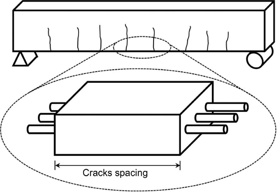
Design procedures for concrete structures are based on the limit state method, which recognises that a structure must simultaneously satisfy a variety of different design requirements related to both strength and serviceability. Reinforcement stress limits, intended to control flexural cracking, are one of the most important requirements for service limit state (SLS) design. Excessive loading can have a detrimental impact on the structure durability in a chloride environment. Indeed, a strong correlation exists between loading-induced concrete damage and heavy corrosion of tensile reinforcements (Castel et al., 2003). In this study, naturally corroding reinforced concrete beams subjected to different sustained loading levels were monitored over a period of 20 years. The results showed that bending cracks do not affect the durability of reinforced concrete, providing that their width is properly controlled. Another important conclusion was that concrete damage (i.e. microcraking) at the steel-concrete interface between bending cracks (Figure 1), so called cover-controlled cracking, was always correlated to areas of severe steel reinforcement corrosion. Based on the assumption that cover-controlled cracking should be limited, a model has been developed to provide alternative reinforcement stress limits for chloride environments (Castel & François, 2011). In this paper, the new reinforcement stress limit is compared to the Australian Standards AS3600 concrete building code (AS3600, 2009) and AS5100.5 concrete bridge code (AS5100, 2004) provisions, and recommendations are provided for the SLS design of reinforced concrete in marine exposure conditions such as concrete in sea water, including permanently submerged, spray zone and tidal/splash zone, as well as coastal constructions located within 1 km of the shoreline.
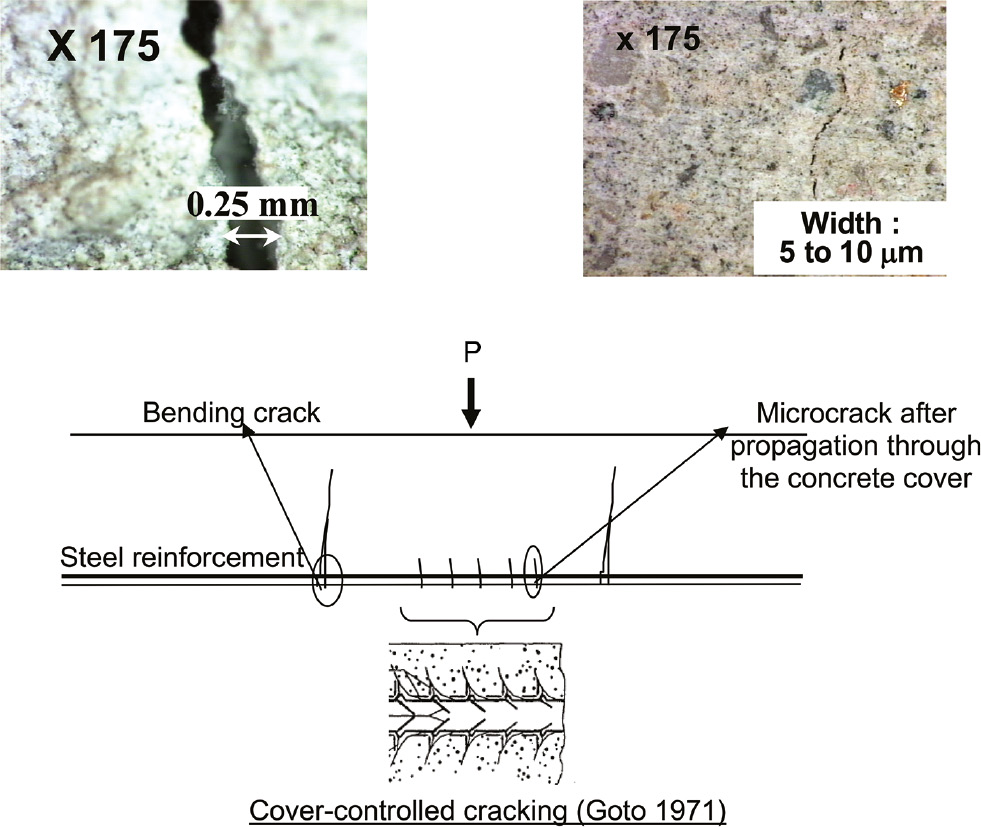
Different types of concrete damage in the tensile zone of a reinforced concrete beam: bending cracks, cover-controlled cracking and microcracking.
2 Influence of bending cracks and cover-controlled cracking
In this section, the influence of bending cracks and cover-controlled cracking on chloride-induced steel corrosion in concrete is discussed. Only cracking due to mechanical loading is considered. Time-dependent effects such as creep and restrained shrinkage-induced cracking are not discussed at this stage. Figure 1 shows the different types of concrete damage that can potentially be observed after cracking in the tensile zone of a reinforced concrete beam: bending cracks, cover-controlled cracking and microcracking. In the following, bending cracking will be always assumed stabilised.
2.1 Sequence of tensile concrete cracking and damage
Before cracking, the concrete strain profile along the depth of the beam is linear (Figure 2A). Consequently, at cracking, the tensile strain of the concrete reaches the ultimate strain in tension εtc,u at the bottom surface of the beam. Thus, at cracking, no steel-concrete bond damage can occur as the concrete strain at the level of the reinforcing bars is significantly lower than εtc,u, particularly in a severe environment as the minimum concrete cover required is usually >50 mm. Cracking stabilisation is reached after all bending cracks have developed. At this stage, the intact concrete between two consecutive bending cracks remains elastic (Castel et al., 2006; Wu & Gilbert, 2009) and the concrete strain is less than the ultimate strain in tension εtc,u. Cracking leads to a redistribution of both steel and concrete tensile strains along the bars between bending cracks. The concrete strain profile along the depth of the beam at half crack spacing is no longer linear, as shown in Figure 2B. The maximum concrete strain is located at the level of the steel bars (Castel et al., 2006). A further increase in loading is required to return to ultimate strain in tension εtc,u at the level of the steel bar, leading to cover-controlled cracking (Figure 2B). According to Goto (1971), cover-controlled internal microcracking develops near the ribs along the steel reinforcement and propagates outwards (Figure 3). The microcracks form at fairly regular intervals along the reinforcing bars. Microcracks can propagate outward through the concrete cover due to a further increase in loading, or to restrained shrinkage, and reach the concrete outer surface (Figure 3). Some microcracks of 5–10 μm width could be observed experimentally at the surface of a beam, as shown in Figure 1.
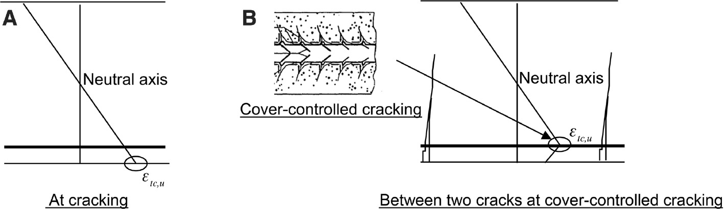
(A) Concrete strain profile at cracking. (B) Concrete strain profile at cover-controlled cracking (mid-way between two consecutive bending cracks).
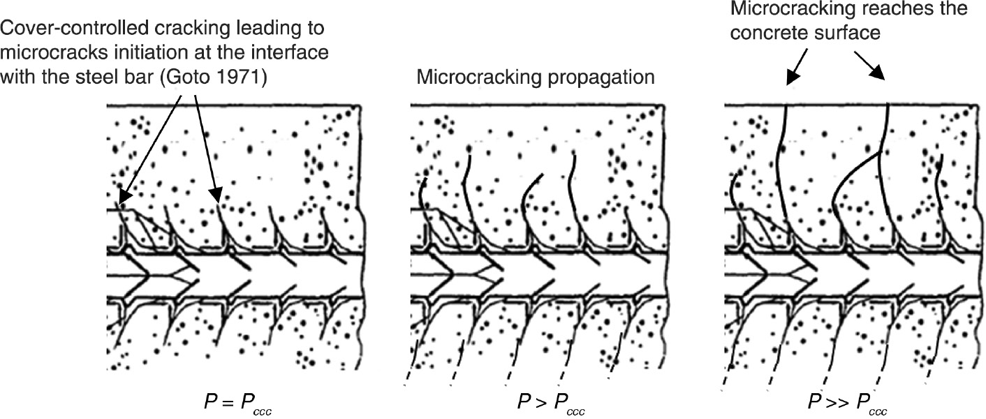
Microcracking propagation through the concrete cover with increasing loading P beyond cover-controlled cracking – Pccc is the loading leading to cover-controlled cracking.
2.2 Influence of bending cracks on steel corrosion process
Bending cracks provide direct access for chloride ions to the reinforcement. Steel corrosion starts after a very short period at the crack tip (François & Arliguie, 1998; François & Castel, 2001); however, both laboratory tests and experience show that corrosion remains very limited providing that the crack width is small enough to allow self-healing (i.e. width <0.2 mm). Cracking self-healing includes different processes. First, residual cement particle hydration and concrete carbonation creating calcite (CaCO3) contribute to healing the crack itself. Second, corrosion products quickly create a barrier at the steel surface, limiting access for oxygen and humidity to the sound steel. As a result, active steel corrosion stops. In this particular case, oxide formation does not lead to any additional concrete cracking, as there is enough room for expansion in the crack. Moreover, the loss of mass required to heal the crack tip is marginal. As a result, this early corrosion does not affect the service life of the structure (François & Arliguie, 1998; François & Castel, 2001).
2.3 Influence of cover-controlled cracking on steel corrosion process
Cover-controlled cracking initiates at the steel-concrete interface, creating voids where humidity, chlorides and oxygen accumulate. Many papers by different authors (Yonezawa et al., 1988; Mohammed et al., 1999; Glass & Reddy, 2002; Castel et al., 2003) report that severe active steel corrosion is always related to the presence of initial defects at the steel-concrete interface with a lower quantity of chloride required for corrosion to start. Moreover, microcracks can propagate outward through the concrete cover due to a further increase in loading or to restrained shrinkage. It has been demonstrated that this microcracking (Figure 1) strongly increases chloride ion diffusion, affecting the service life of the structure. Analysis of chloride profiles in 14-year-old naturally corroded beams showed that concrete cover microcracking can lead to an increase in the apparent chloride diffusion coefficient of about 40% (Castel et al., 2001). As a result, cover-controlled cracking should be limited in chloride environments through appropriate SLS design procedures.
3 Modelling concrete strain distribution between cracks
Considering the assumption that cover-controlled cracking between bending cracks should be limited, a model has been developed aiming to assess in detail the distribution of both steel reinforcement and concrete strains between two consecutive stabilised bending cracks (Castel & François, 2011). Experimental research by Castel et al. has shown that concrete strains in the tensile region of cracked reinforced concrete beams are not linear; greater tensile strains were measured at the level of reinforcement compared to regions further away. Based on these results, Castel & François (2011) developed the strain distribution model depicted in Figure 4, in the cross-section located at mid-spacing between two consecutive cracks. It is a tri-linear strain distribution. Considering that the concrete tensile strain along the reinforcing bar is always maximum at mid distance between the cracks, εtc,max is the actual maximum tensile strain in the entire concrete block located between two bending cracks. In Figure 4, y0E is the neutral axis depth calculated before cracking, d is the effective depth, h and b are the total depth and the thickness of the beam cross-section, and a is the thickness of the reinforcing bar layers (equal to a single bar diameter if only one layer of reinforcement is used).
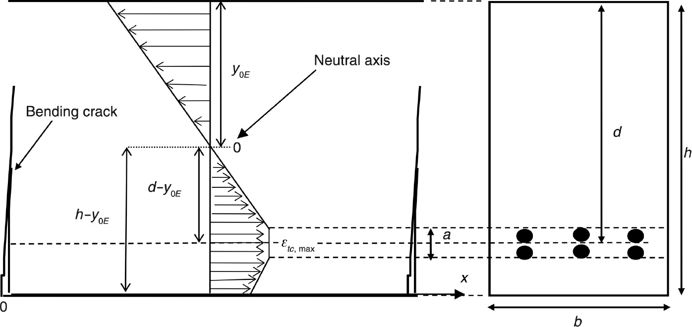
Concrete strain profile in a cross-section located at mid crack spacing.
Assuming that the cross-section at mid crack spacing is subjected to the same bending moment as the cross-section at crack location, this assumption being justified by the extremely low ratio between the half crack spacing and the beam span, the maximum concrete strain εtc,max can be calculated using Eq. (1), showing that εtc,max is proportional to the steel strain at the crack location εs. All details related to the derivation of Eq. (1) are available in Castel & François (2011).
where znc and zc are the lever arms of the internal forces. znc and zc are calculated before cracking and at the cracked cross-section, respectively. For the SLS design, it is considered that concrete behaviour in compression remains linear elastic. εs is the steel strain at the cracked cross-section; As is the steel cross-section. αe is the ratio between the instantaneous elastic modulus of steel and concrete. Act.ef is the effective area of concrete in tension. Act.ef is derived from the concrete strain profile presented in Figure 4 and can be calculated using Eq. (2). All details related to the derivation of Act.ef are available in Castel et al. (2006).
The tensile region of a reinforced concrete beam or slab is considered to be analogous to the tension chord described in Figure 5. The concrete cross-section of the tension chord is equal to the effective area of concrete Act.ef [Eq. (2)] working at the constant strain εtc,max at mid crack spacing [Eq. (1)]. The typical non-linear distribution of the concrete strain εtc(x) along the tension chord between two cracks according to Castel & François (2011) is presented in Figure 6.
Idealisation of the tensile region of beam between two cracks as a tension chord.
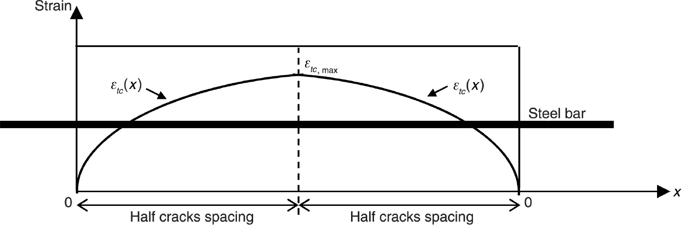
Non-linear distribution of concrete strain εtc(x) along the tension chord between two cracks.
Figure 7 shows the typical variation of the concrete tensile stress σtc,max versus the ratio of the effective area of concrete Act.ef to steel reinforcement cross-section As. For that particular example, the stress in the reinforcing bar at the crack location is 250 MPa, αe is equal to 7 (i.e. concrete elastic modulus equal to 30 GPa) and ratio znc/zc is equal to 0.9. As shown in Figure 7, the tensile region of a reinforced concrete beam is considered equivalent to a concrete tension chord with a square cross-section reinforced with a single 16-mm-diameter steel bar. The ratio Act.ef/As ranges between 50 and 240, as a result of increasing the concrete cross-section depth b from 100 to 220 mm. Increasing the concrete area leads to a decrease in σtc,max. Indeed, at mid crack spacing, the load applied to the tension chord (i.e. 250 MPa time the steel cross-section) is shared between the steel and the concrete. The concrete contribution in carrying the tension load is increased by increasing the concrete area, resulting in a stress reduction in both steel and concrete. On the contrary, cover-controlled cracking can be triggered by excessively reducing the concrete cross-section. For this particular example, cover-controlled cracking is triggered when σtc,max reaches the assumed concrete tensile strength (ftc=3.5 MPa) for a ratio Act.ef/As equal to 65. This example highlights the sensitivity of the model to the percentage of steel in the concrete cross-section. Another important point is that prescribing a steel stress limitation (i.e. 250 MPa for this example) is not sufficient to avoid cover-controlled cracking, as the level of stress in the concrete is highly dependent on the concrete cross-section involved.
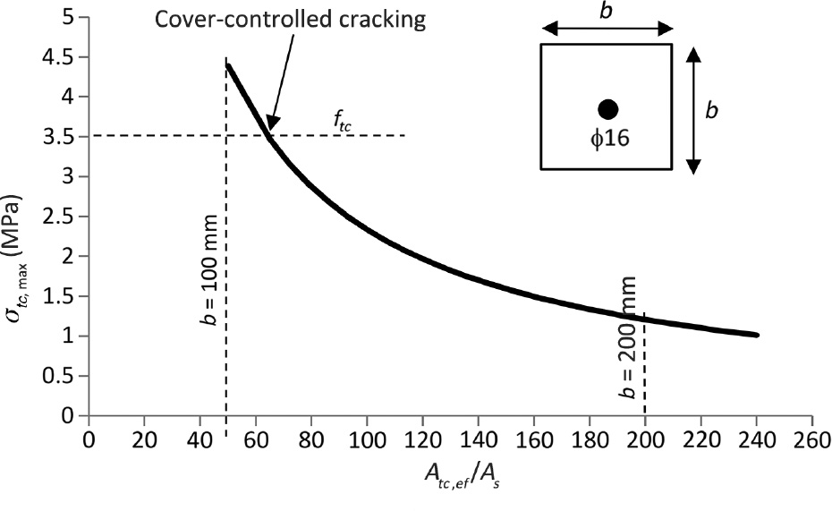
Typical variation of the concrete tensile stress σtc,max versus the ratio effective area of concrete Act.ef to steel reinforcement cross-section As.
4 New steel reinforcement stress limitation
Cover-controlled cracking is assumed to occur when the concrete strain εtc,max [Eq. (1)] reaches the ultimate concrete strain in tension εtc,u [Eq. (3)] under SLS load combinations:
where Ec and ftc are the concrete elastic modulus and the concrete tensile strength, respectively. Rearranging Eq. (1) in terms of εs and substituting the value of εtc,max=εtc,u yields the tensile stress in the reinforcement at the crack location σs,ccc required to initiate cover-controlled internal cracking under SLS load combinations:
The steel stress limitation σs,ccc is proportional to the concrete tensile strength. The range of variation of αe is marginal compared to ratio Act.ef/As. As a result, the second most important influencing parameter is the ratio of effective area of concrete Act.ef to steel reinforcement cross-section As, as already mentioned in the previous section. In the next section, this new reinforcement stress limitation is compared to the AS3600 and AS5100.5 provisions. The sensitivity of σs,ccc to the ratio znc/zc will also be discussed in the next section.
5 Comparison between AS3600/AS5100 provisions and the new reinforcement stress limitation
For beams, crack control related to load effects in the bridge code, AS5100.5, is considered for the following two cases (clause 8.6):
SLS load combinations.
Permanent effects at the SLS for exposure classifications B2, C and U.
In case (i), the reinforcement stress limit ranges from 450 to 160 MPa depending on the nominal bar diameter and the centre-to-centre bar spacing. The same reinforcement stress limitation is also adopted in AS3600 for all exposure classifications. This stress limitation aims to control the maximum bending crack width to a value of ≤0.3 mm. The severity of the environment is taken into account in the bridge code considering case (ii) for exposure classifications B2, C and U, where stress limits are reduced to values ranging from 340 to 80 MPa. This second stress limitation aims to control the maximum bending crack width under permanent effects only to a value of ≤0.2 mm. This is a major difference compared to the new model proposed, where the stress limitation in severe environment considers all service loadings, not only permanent effects.
The new reinforcement stress limitation is compared to the AS3600 and AS5100.5 provisions by analysing five types of reinforced concrete members: small beams, slabs, footings, bridge headstock and arches. Bridge headstocks are the components that transfer loads from the superstructure to the piers. The characteristic compressive strength of the concrete considered is 50 MPa. The characteristic flexural tensile strength (AS5100.5 – clause 6.1.1) is used to calculate the reinforcement stress limitation [Eq. (4)]. The characteristic flexural tensile strength is 4.24 MPa. The elastic modulus of the concrete is 34,800 MPa (AS5100.5 – clause 6.1.2).
Recall that the main difference between the two approaches is that the AS3600 and AS5100.5 stress limitations aim to control the bending crack width (i.e. crack widths around 0.3 or 0.2 mm), whereas the new model aims to avoid cover-controlled cracking between the cracks regardless of the crack width. According to the reasons provided in Sections 2.2 and 2.3, both approaches are relevant and should be considered for the SLS design. As a result, this analysis aims to determine which approach is the most conservative depending on the reinforced concrete cross-section considered.
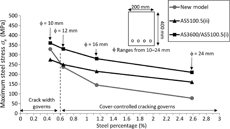
Figure 8 shows AS3600/AS5100.5 and the new model provisions for small beams with 400×200 mm concrete cross-section reinforced with four steel bars with a diameter ranging from 10 to 24 mm. The stress limitation is plotted versus the steel reinforcement percentage of the beams, ρ [Eq. (5)]. The values of the critical parameters of the small beam cross-sections are presented in Table 1.
Small beam 400×200 mm cross-section.
Small beams-slabs.
| Small beams |
Slabs |
|||||||
|---|---|---|---|---|---|---|---|---|
| φ10 |
φ12 |
φ16 |
φ24 |
φ10 |
φ12 |
φ16 |
φ24 |
|
| Atc,ef (mm2) | 234.1 | 232.6 | 228.2 | 213.8 | 737.6 | 739.3 | 738.7 | 723.0 |
| As (mm2) | 3.14 | 4.52 | 8.04 | 18.09 | 7.85 | 11.31 | 20.11 | 45.24 |
| Atc,ef/As | 74.51 | 51.42 | 28.37 | 11.82 | 93.91 | 65.36 | 36.74 | 15.98 |
| ρ (%) | 0.45 | 0.65 | 1.15 | 2.58 | 0.39 | 0.56 | 1.01 | 2.26 |
| znc/zc | 0.87 | 0.86 | 0.89 | 0.92 | 0.84 | 0.85 | 0.87 | 0.90 |
Figure 8 shows that the AS3600 and AS5100.5(i) provisions are non-conservatives compared to the new model requirement for normally to heavily reinforced beams. For lightly reinforced beams (ρ<0.5), the difference between the two approaches becomes marginal because the reinforcement stress leading to cover-controlled cracking increases drastically. This is in accordance with the results presented in the Figure 7. The AS5100.5(ii) provision for severe environments appears to be conservative for steel reinforcement percentage ρ<0.6%, which means that crack width control governs the SLS design; however, it is important to keep in mind that AS5100.5(ii) considers permanent effects at the SLS only, whereas the new model considers all SLS load combinations. For steel reinforcement percentage ρ>0.6%, the AS5100.5(ii) provision is not conservative and cover-controlled cracking governs the SLS design. As a result, the new model limitation should be applied. In this case, the new model limitation requires lower steel stress compared to the existing codes. As a result, more steel must be provided. Alternatively, to increase the steel stress limitation σs,ccc [Eq. (4)], the size of the concrete cross-section can be increased, allowing for more tension stiffening.
For slabs, the provisions for crack control in AS3600 and AS5100.5 are the same and are compared to the new model limitations. Figure 9 shows the AS3600, AS5100.5 and new model provisions for slabs with 250×1000 mm concrete cross-section reinforced with 10 steel bars with a diameter ranging from 10 to 24 mm. The stress limitation is plotted versus the steel reinforcement percentage of the beams, ρ [Eq. (5)]. The values of the critical parameters of the slabs cross-section are presented in Table 1. The results show that for a steel reinforcement percentage ρ<0.5%, the AS3600 and AS5100.5 provisions are conservative, which means that crack width control governs the SLS design. For a steel reinforcement percentage ρ>0.5%, cover-controlled cracking governs and the new model limitations should be applied. As mentioned before for small beams, more steel must be provided. Alternatively, to increase the steel stress limitation σs,ccc [Eq. (4)], the size of the concrete cross-section can be increased, allowing for more tension stiffening.
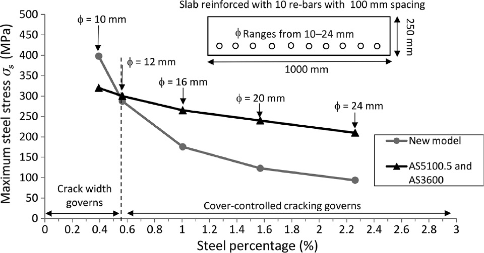
Slab 1000×250 mm cross-section.
Figures 10 and 11 compare the AS5100.5(i) (AS3600), AS5100.5(ii) and new model provisions for footings and bridge headstocks. Footings are 900×1000 mm concrete cross-section reinforced with eight steel bars with a diameter ranging from 20 to 40 mm. Headstocks are 1800×2000 mm concrete cross-section reinforced with 19 steel bars with a diameter ranging from 20 to 40 mm. The values of the critical parameters of the footing and bridge headstock cross-sections are presented in Table 2. For this type of beam with very large concrete cross-section, it appears that the AS5100.5 provisions are conservative in all cases. Crack width control governs the SLS design. According to the theoretical model proposed, for very lightly reinforced concrete beams (ρ<0.2), steel reinforcement stress can reach the elastic limit before any cover-controlled cracking would occur (Figure 11).
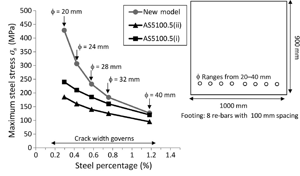
Footing 900×1000 mm cross-section.
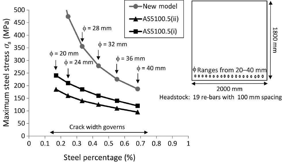
Headstock 1800×2000 mm cross-section.
Footings-headstocks.
| Footings |
Headstocks |
|||||||
|---|---|---|---|---|---|---|---|---|
| φ20 |
φ24 |
φ32 |
φ40 |
φ20 |
φ24 |
φ32 |
φ40 |
|
| Atc,ef (mm2) | 2470.8 | 2457.4 | 2417.2 | 2360.5 | 9436.9 | 9395.8 | 9280.7 | 9122.8 |
| As (mm2) | 25.13 | 36.19 | 64.34 | 100.53 | 59.69 | 85.95 | 152.80 | 238.76 |
| Atc,ef/As | 98.31 | 67.90 | 37.57 | 23.48 | 158.10 | 109.31 | 60.73 | 38.21 |
| ρ (%) | 0.29 | 0.43 | 0.76 | 1.18 | 0.17 | 0.24 | 0.44 | 0.68 |
| znc/zc | 0.87 | 0.88 | 0.89 | 0.9 | 0.86 | 0.87 | 0.88 | 0.89 |
The last reinforced concrete members analysed are 400×1500 mm arch beam cross-sections with 12 steel bars with diameters ranging from 12 to 40 mm (Figure 12). The values of the critical parameters of the arch beams are presented in Table 3. First comparing AS5100.5(i) and the new model limitations, it appears that for ρ<0.7%, the AS5100.5(i) provisions are conservative and crack width control governs the SLS design. For a steel reinforcement percentage ρ>0.7%, cover-controlled cracking governs and the new model limitations should be applied. Comparing the AS5100.5(ii) and new model limitations, cover-controlled cracking governs for ρ>1.1%, and the difference between the two limitations with increasing ρ is marginal for this type of beam cross-section. However, again, it is important to keep in mind that AS5100.5(ii) considers permanent effects at the SLS only, whereas the new model considers all SLS load combinations.
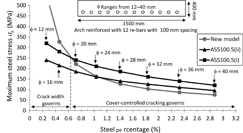
Arch 400×1500 mm cross-section.
Reinforced concrete arches.
| Arches |
||||
|---|---|---|---|---|
| φ12 |
φ24 |
φ32 |
φ40 |
|
| Atc,ef (mm2) | 1789.0 | 1769.3 | 1727.1 | 1664.8 |
| As (mm2) | 13.57 | 54.29 | 96.51 | 150.80 |
| Atc,ef/As | 131.82 | 32.59 | 17.89 | 11.04 |
| ρ (%) | 0.26 | 1.03 | 1.84 | 2.87 |
| znc/zc | 0.85 | 0.89 | 0.91 | 0.92 |
For all cross-sections considered, the ratio znc/zc ranges between 0.84 and 0.92. This ratio leads to a reduction in the steel stress limit σs,ccc [Eq. (4)], resulting from the reduction of the neutral axis depth at crack locations compared to that before cracking. The ratio znc/zc could be considered as equal to 0.9, allowing the simplification of the steel stress limitation σs,ccc [Eq. (4)], as follows:
where As is the steel cross-section. Act.ef is the effective area of concrete in tension [Eq. (2)]. αe is the ratio between the instantaneous elastic modulus of steel and concrete. f′cf is the characteristic flexural tensile strength of concrete (AS5100.5 – clause 6.1.1). Equation (6) is recommended for implementation in both AS5100 and AS3600 codes under SLS load combinations. Equation (6) should be used in any aggressive environments leading to a high risk of severe reinforcing steel corrosion (i.e. exposure classifications B2, C and U, if applicable). Both the existing code provision and Eq. (6) results should be considered. The most conservative stress limitation should be used for the SLS design.
Figure 13 shows the influence of the concrete cover on the stress limit [Eq. (6)]. Small beams with 400×200 mm concrete cross-section are considered, reinforced with four 12-mm-diameter steel bars. Concrete cover to the main bars ranges from 20 to 50 mm. Figure 13 shows that concrete cover does not significantly influence the steel stress limit.

Influence of the concrete cover on the steel stress limitation.
The fib Structural Concrete Textbook vol. 3 (fib 2009) suggests that specifying small allowable crack widths can have adverse effects on durability, as the formulae used to calculate crack widths tend to lead designers to minimise cover depth and use many small diameter bars at small spacing. A better result may be achieved with greater cover and less congested reinforcement, leading to a greater depth of well-compacted concrete cover and improved corrosion resistance, even if surface crack widths are increased.
The stress limits in the Australian codes are not affected by depth of cover, but do allow very high stresses with high reinforcement ratios for closely spaced reinforcement. The proposed new stress limits, based on the limitation of cover-controlled cracking, provide a rational basis to design for improved durability, without introducing difficulties in specifying sufficient cover or leading to design choices that will result in excessively congested reinforcement.
6 Conclusions
Based on the assumption that cover-controlled cracking should be limited, a model has been developed providing an alternative reinforcement stress limitation for the SLS design of reinforced concrete in marine exposure conditions, such as concrete in sea water, including permanently submerged, spray zone and tidal/splash zone, as well as coastal constructions located within 1 km of the shoreline. In this paper, the new reinforcement stress limitation was compared to the AS3600 and AS5100.5 code provisions. The Australian code stress limitations aim to control the bending crack width, whereas the new model aims to avoid cover-controlled cracking between the cracks, regardless of the crack width. Both approaches are relevant and should be considered for the SLS design. As a result, the analysis aimed to determine which approach is the most conservative depending on the reinforced concrete cross-section considered. Analysis of five different types of reinforced concrete cross-sections, including small beams, slabs, footings, bridge headstock and arches, showed that the new model is very sensitive to the reinforcement percentage of the cross-section. As a result, the existing AS3600 and AS5100.5 code provisions are more conservative than the new limitation for lightly to normally reinforced concrete cross-section. In this case, crack width control governs the SLS design. However, for normally to heavily reinforced concrete cross-section, the new model provides more conservative results suggesting that cover-controlled cracking governs the SLS design. Equation (6) is recommended for implementation in both AS5100 and AS3600 codes for SLS design in aggressive environments having a high risk of chloride induced reinforcing steel corrosion.
-
Funding: ARC Australian Research Council, Grant Number: “Discovery Project DP140100529”.
References
Andrade C, Cesetti A, Mancini G. Tondolo F. Estimation of corrosion attack in reinforced concrete by means of crack opening. Struct Concrete 2016; 17: 533–540.10.1002/suco.201500114Search in Google Scholar
AS3600. Standards Australia Reinforced Concrete Design AS3600–2009.Search in Google Scholar
AS5100. Standards Australia Bridge Design Part 5: Concrete AS 5100–2004.Search in Google Scholar
Bossio A, Lignola GP, Fabbrocino F, Monetta T, Prota A, Bellucci F, Manfredi G. Nondestructive assessment of corrosion of reinforcing bars through surface concrete cracks. Struct Concrete 2017; 18: 104–117.10.1002/suco.201600034Search in Google Scholar
Castel A, François R. Modelling of steel and concrete strains between primary cracks for the prediction of cover-controlled cracking in RC-beams. Eng Struct 2011; 33: 3668–3675.10.1016/j.engstruct.2011.08.001Search in Google Scholar
Castel A, François R, Arliguie G. Mechanical behaviour of corroded reinforced concrete beams – Part 1: experimental study of corroded beams. Mater Struct 2000a; 33: 539–544.10.1007/BF02480533Search in Google Scholar
Castel A, François R, Arliguie G. Mechanical behaviour of corroded reinforced concrete beams – Part 2: bond and notch effects. Mater Struct 2000b; 33: 545–551.10.1007/BF02480534Search in Google Scholar
Castel A, Francy O, François R, Arliguie G. Chloride diffusion in reinforced concrete beam under sustained loading. In: CANMET/ACI Fifth International Conference on Recent Advances in Concrete Technology 2001; ACI SP 200: 647–662.Search in Google Scholar
Castel A, Vidal T, François R. Effective tension active cross-section of reinforced concrete beams after cracking. Mat Struct 2006; 39: 103–113.10.1617/s11527-005-9038-zSearch in Google Scholar
Castel A, Vidal T, François R, Arliguie G. Influence of steel-concrete interface quality on reinforcement corrosion induced by chlorides. Mag Concrete Res 2003; 55: 151–160.10.1680/macr.2003.55.2.151Search in Google Scholar
fib. Structural concrete textbook on behaviour. Design and performance 2009; second edition vol. 3, fib Bulletin 53.Search in Google Scholar
François R, Arliguie G. Influence of service cracking on reinforcement steel corrosion. ASCE J Mater Civil Eng 1998; 10: 14–20.10.1061/(ASCE)0899-1561(1998)10:1(14)Search in Google Scholar
François R, Castel A. Discussion of the paper: influence of bending cracks and water-cement ratio on chloride-induced corrosion of main reinforcing bars and stirrups by N Otsuki, S Miyazato, N Diola and H Suzuki. ACI Mater J 2001; 98: 276–278.Search in Google Scholar
François R, Castel A, Vidal T. A finite macro-element for corroded reinforced concrete. Mater Struct 2006; 39: 571–584.10.1617/s11527-006-9096-xSearch in Google Scholar
Glass GK, Reddy B. The influence of the steel concrete interface on the risk of chloride induced corrosion initiation. COST 521 Final Project Reports UK6 2002; 227–232.Search in Google Scholar
Goto Y. Cracks formed in concrete around deformed tension bars. ACI J 1971; 68: 244–251.10.14359/11325Search in Google Scholar
Mohammed TU, Otsuki N, Hisada M. Corrosion of steel bars with respect to orientation in concrete. ACI Mater J 1999; 96: 154–159.10.14359/439Search in Google Scholar
Rodriguez J, Ortega LM, Casal J. Load carrying capacity of concrete structures with corroded reinforcement. Construct Build Mater 1997; 11: 239–248.10.1016/S0950-0618(97)00043-3Search in Google Scholar
Wu HQ, Gilbert RI. Modeling short-term tension stiffening in reinforced concrete prisms using a continuum-based finite element model. Eng Struct 2009; 31: 2380–2391.10.1016/j.engstruct.2009.05.012Search in Google Scholar
Yonezawa T, Ashworth V, Procter RPM. Pore solution composition and chloride effects on the corrosion of steel in concrete. Corros Eng 1988; 44: 489–499.10.5006/1.3583967Search in Google Scholar
©2019 Walter de Gruyter GmbH, Berlin/Boston
Articles in the same Issue
- Frontmatter
- Editorial
- Environmental degradation of reinforced concrete structures
- Review
- Corrosion behaviour of stainless steel reinforcement in concrete
- Original articles
- New service limit state criteria for reinforced concrete in chloride environments
- The performance of corroded lap splices in reinforced concrete beams
- Corrosion effects on seismic capacity of reinforced concrete structures
- Assessment of reinforced concrete structures in marine environment: a case study